Optimization of Low Temperature Differential Stirling Engine Regenerator Design

Adv. Sci. Technol. Eng. Syst. J. 5(2), 272–279 (2020);
 DOI: 10.25046/aj050235
Stirling engines working with relatively low temperature are attractive for the future, especially for applications like water pumping without concentration system and low temperature heat recovery. The present work is the continuation of a series of works on the optimization of this type of machines. The main objective of this paper is to investigate the performance of low temperature differential Stirling engine (LT-SE) regenerator by adopting a theoretical model based on heat transfer and frictional pressure drop correlations. Since the speed and the Reynolds number of this type of machines are low, the correlations concerning pressure drop were validated by comparing the calculated results with experimental measurements on a LT-SE prototype. Based on this model, several calculations were conducted in order to know how LT-SE designers can attain a desired value for regenerator effectiveness. In fact, the effect of six parameters on regenerator performances was investigated. Studied parameters are: engine speed, regenerator volume, regenerator porosity, wires diameter, working fluid type and regenerator fibers arrangement. The effect of these parameters was especially checked on pressure drop, heat transfer coefficient, regenerator and engine efficiencies. Results indicated many designing recommendations for LT-SE having the same power range of our prototype: a regenerator length around Lreg= 1.41 × displacer stroke, a wire diameter around dw= 0.15mm, a porosity around β=0.75. Results indicated also that the most performant working fluid is Helium.
1. Introduction
The Stirling engine is one of the methods for converting heat into mechanical energy with a theoretically maximum efficiency [1,2]. This is due to the use of the regenerator, which is a heat exchanger acting as an energy economizer [3]; It is a porous matrix, with a great storage capacity of thermal energy and a great heat transfer surface [4]. Stirling engine regenerators are generally composed either from woven screens or random fibers [5].
During half of the Stirling motor cycle, heat is transferred from the working fluid to the matrix. During the other half, the heat is transferred in the opposite direction. Thus, for a whole cycle, the transferred heat between working fluid and the matrix is null.
The very first mathematical theories for regenerator’s functioning description were published around 1920, more than 100 years after Stirling engines invention. Later, experimental and theoretical studies of regenerators were conducted in order to identify thermodynamic phenomena acting in this important component, and to predict Stirling engines behavior. Examples of these studies include those of Kays and London [6], who presented correlations between parameters based on experimental studies in order to find out the working fluid Darcy friction factor. Later, Sodré and Parise [7] conducted experimental tests in order to identify the pressure drop in an annulus duct filled of a woven matrix. Similarly, Tanaka et al. [8] have studied flow and heat transfer characteristics of the regenerator for a periodic flow. Many numerical studies were also conducted in order to analyze the flow through regenerator matrices based on 3D CFD Modeling [9]. The finite element method seems suitable for such analysis as indicated by Rühlich and Quack [10], Gedeon and Wood [11], Ibrahim et al.[12, 13], Tew et al. [14] and others. These studies have stressed the importance of flow simulation for understanding characteristics of fluid friction. Combined experimental and numerical studies have quantified the pressure drop and heat transfer rate [15]. In addition, effort has been invested to study the design and structural parameters of mesh type regenerators of Stirling cryocoolers [16].
The present study contributes to the optimization of a category of solar low temperature differential Stirling engines (LT-SE). Prototypes were designed and constructed within a cooperation framework between Dresden University- Germany, and Moulay Ismail University- Morocco. These prototypes are designed to be simple and cheap for providing a solar pumping water system, and thus, contributing to human development [17].
Since this category of Stirling motors is to be developed and optimized, the authors studied earlier many parameters to find out there optimal values [18]. This paper aims to complete this development process by studing and optimizing one of the critical components of this type of engines: the regenerator.
In the literature, studies about regenerators are focused on high and moderate temperature differential Stirling engines. This paper aims to fill out the existing lack about regenerators of low temperature differential engines [19,15]. In this work a theoretical study of regenerators is held, taking into account the pressure drop inside it, heat transfer coefficient, regenerator and engine efficiencies. Since the speed and the Reynolds number of this type of machines are low, the correlations concerning pressure drop were validated by comparing the calculated results with experimental measurements on a LT-SE prototype.
After validation of the theoretical model, a parametrical study is conducted in order to find optimal values of a number of design and functioning parameters. The considered prototype is a beta type of LT-SE, called SUNWATER 3. Figure 1 and Table 1 present its main components and geometrical specifications.
Table 1: Technical specifications and calculation data of SUNWATER 3
| Parameter | Value |
| Displacer diameter | 1.35 m |
| Absorber diameter | 1.51 m |
| Working piston diameter | 0.29 m |
| Regenerator volume | 0.063 m3 |
| Fibers arrangement | Random |
| Hot temperature | 70°C |
| Cold temperature | 20 °C |
| Working fluid | Air |
| Cooling system | Water cooled |
| Section area of the regenerator housing | ≈ 0.36 m2 |
| Average pressure | ≈1.1 bars |
2. Theoretical analysis
In order to identify the effect of a number of regenerator parameters on its efficiency and on LT-SE efficiency, some correlations and equations were adopted, which are suitable for Stirling engines characteristics’.
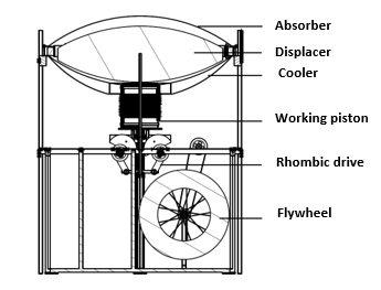 Figure 1: Illustration of SUNWATER 3
2.1 Correlations for Darcy friction factor and Nusselt number
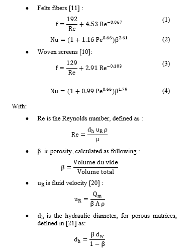
Experimental studies of Gedeon and Wood [11] about regenerators have led to the correlations of Darcy friction factor and Nusselt number for two types of regenerators: felts and woven screens, given in equations (1 – 4):
2.2. Convective heat transfer coefficient and pressure drop:
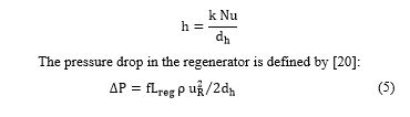
The convective heat transfer coefficient is defined based on Nusselt number as follows:
2.3. Regenerator efficiency
Based on Tanaka et al. work [8], the regenerator efficiency can be expressed based on the number of transfer units as follows:
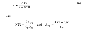
et are average values of convective heat transfer coefficient and mass flow rate respectively.
2.4. Engine efficiency
In order to evaluate LT-SE efficiency taking into account regenerator characteristics, we adopt (7). Pressure drop in other heat exchangers (absorber and cooler) was not considered, as it is relatively low in comparison with the charge loss in the regenerator and does not affect the regenerator evaluation [8][22].
 Wind is the indicated work, which does not take into account any loss. Wr is the work lost in the regenerator by friction of the fluid against regenerator fibers. Wc is the work during the expansion. And Qperte is the heat that hot source should give additionally, due to the regenerator imperfection.
We suppose that during the passage of the fluid from the hot side to the cold side, the same heat amount (Qperte) should be evacuated additionally by the cold source, due to the regenerator imperfection. These energies are calculated as in (8).
![]() The indicated work is calculated based on the variation of the total volume and the instantaneous pressure. Two Schmidt hypothesis were adopted; the harmonic variation of engine volumes, and the uniform pressure inside the engine [23]. Our machine can be represented as in Figure 2.
The indicated work is calculated based on the variation of the total volume and the instantaneous pressure. Two Schmidt hypothesis were adopted; the harmonic variation of engine volumes, and the uniform pressure inside the engine [23]. Our machine can be represented as in Figure 2.
 Figure 2: Schematic representation of a beta Stirling engine [23]
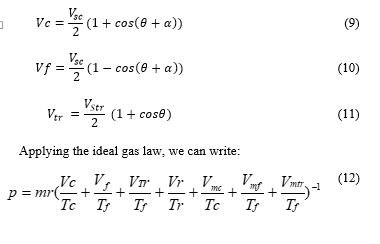
Vmc, Vmf and Vmtr are dead volumes in the hot side, cold side and in the working space respectively. VR is the regenerator volume, Vtr, VC and Vf are the working space, hot and the cold instantaneous volumes respectively.
dVe and dVc are respectively the variation of the total volume during the expansion and the compression. Ve, Vc, Vtr are defined in (9 – 12).

 3. Validation set up and parametric study
The correlating expressions for pressure drop produced by wood [11] concern two types of regenerator material: woven screens and metal felts. These felts have a random fiber orientation but with the fibers lying predominantly transverse to the flow direction. In SUNWATER 3 prototype, we use random fiber regenerator due to its simplicity and cost. For this reason, an experimental study is carried out to verify the validity of these correlations for our case. Measurement of pressure drop was conducted for SUWATER 3 [24] in order to compare experimental results to theoretical calculations. Pressure sensors in hot and cold sides were installed (Figure 3).
After the experimental validation, effects of many regenerator parameters are studied for finding their optimal values. The parameters are: engine speed, regenerator volume, porosity, wire diameter, working fluid type, and fibers arrangement. The impact of the former parameters on pressure drop in the regenerator, heat transfer coefficient, the regenerator and the engine efficiencies was investigated using equations developed in the theoretical analysis.
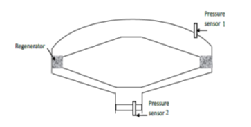 Figure 3: Experimental measurement of pressure drop [24]
Results were found using a calculation program on Microsoft EXCEL, which calculates for a thermodynamic cycle (a complete revolution of the engine flywheel), at a step of 1°, the engine internal chambers instantaneous volumes , and , the mass flow rate, the instantaneous pressure, the hydraulic diameter, the fluid velocity, Reynolds number, pressure drop, heat transfer factor, etc.
The prototype SUNWATER 3 was taken as a calculation example. Table 2 indicates data for studied cases. Each studied case shows effect of the variation of selected parameter on engine performance.
4. Results and discussions
4.1. Experimental validation of pressure drop correlation
Figure 4 presents experimental results. It shows the variation of the difference between pressures given by sensors 1 and 2 in time. This pressure difference represents the pressure drop in the engine.
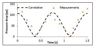 Figure 4: Pressure drop measurement and calculation during one cycle
The comparison between experimental and theoretical curves shows a good agreement, despite some small differences. These differences are due to the structure of our regenerator, and to the fact that sensors give pressure drop caused by regenerator and heat exchangers in hot and cold side, whereas the model gives the pressure drop caused by the regenerator only. Indeed, the pressure drop in the machine is mostly due to the regenerator. This result validates the calculation model adopted, especially for pressure drop correlation. Therefore, we can use the developed model to conduct a parametric study for optimization of LT-SE.
4.2. Effect of engine speed
In order to find the effect of engine speed on regenerator and engine efficiencies, we calculated the former values for many engine’s speeds (data are available in Table 2, case 1). Results are shown in Figure 5.
 Figure 5: Variation of regenerator and engine efficiencies according to engine speed
Table 2: The parameters range of parametric study
| Case | Engine Speed (rpm) | Regenerator length (m) | Porosity β (-) | Wire diameter dw (mm) | Fluid type | Fibers type |
| 1 | [10-100] | 0.1 | 0.9 | 0.2 | Air | random |
| 2 | 40 | [0,03-0,5] | 0.9 | 0.2 | Air | random |
| 3 | 40 | 0.1 | [0,6-1] | 0.2 | Air | random |
| 4 | 40 | 0.1 | 0.75 | [0,05-0,5] | Air | random |
| 5 | 40 | 0.1 | 0.8 | 0.2 | variable | random |
| 6 | 40 | 0.1 | 0.8 | 0.2 | Air /Helium | variable |
Figure 5 shows that engine performances decrease as engine speed increases. This result is due to the increasing of pressure drop in regenerator with speed. High speed has also bad effect on heat transfer in regenerator, because of the low time contact between the gas and the matrix. Hence, it is advisable to run LT-SE at a low speed in order to improve its performance.
4.3. Effect of regenerator volume
In order to identify the regenerator volume effect on LT-SE for a fixed cross section area, we varied the regenerator length (Table 2, case 2) and calculated pressure drop, convective heat transfer coefficient and regenerator and machine efficiencies. Results are shown in Figures 6 and 7.
Figure 6 indicates that heat transfer coefficient is not affected by the regenerator length, as hydraulic diameter and engine speed have not changed. However, pressure drop decreases with the increase of the regenerator length.
Figure 7 indicates that it exists an optimal regenerator length (Lreg= 0.12m), for which the engine efficiency is maximum. After this value, the negative effect of pressure drop is more significant than the increasing of the contact surface between the gas and the regenerator. The optimal regenerator length for LT-SE is then about:
 Figure 6: Effect of regenerator length on pressure drop and heat transfer coefficient
4.4. Effect of porosity
Figure 8 presents the effect of porosity on pressure drop and heat transfer coefficient of the regenerator (Table 2, case 3). It indicates that pressure drop decreases with increase of regenerator porosity. Considering heat transfer coefficient, the value of porosity which maximizes it is β=0.8.
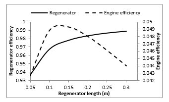 Figure 7: Effect of regenerator length on engine and regenerator efficiencies
 Figure 8: Variation of heat transfer coefficient and charge loss according to porosity
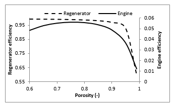 Figure 9: Variation of regenerator and engine efficiencies according to porosity
Figure 9 shows the effect of porosity on the regenerator and engine efficiencies. It indicates that these efficiencies follow the same trend as the heat transfer coefficient. Thus, it’s recommended to adopt the optimal value β=0.8, giving the best performances.
4.5. Effect of regenerator wire diameter
The effect of regenerator wire diameter (Table 2, case 4) is illustrated on Figure 10. An optimal value for wire diameter is found to be dw=0.15mm, corresponding to hydraulic diameter dh=0.45mm.
Work of Tanaka et al. [8] based on experimental tests indicates also an optimal wire diameter. They found, for regenerators longer than 70mm (which is the case for our adopted values), that there is an optimal value for wire diameter. But it was not defined, due to smaller variation range of regenerator length.
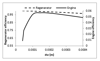 Figure 10: Variation of engine and regenerator efficiencies according to wire diameter dw
4.6. Effect of working fluid
Effects of three working fluids: hydrogen, helium and air, on regenerator and engine efficiencies were investigated.
Figures 11 and 12 present the effect of working fluid type on the variation of heat transfer coefficient and pressure drop during a complete cycle. Calculation data are available in Table 2, case 5. These figures indicate that hydrogen is the most performant fluid among the studied fluids, giving the best heat transfer coefficient and causing the less pressure losses. These results are due to the fact that hydrogen is the lightest and less viscous fluid among the studied fluids (see Table 3).
 Figure 11: Cyclic variation of heat transfer coefficient for several working fluids
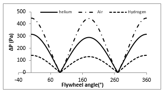 Figure 12: Cyclic pressure drop variation for several working fluids
Figure 13 indicates the regenerator and engine efficiencies for the studied working fluids. Helium and hydrogen give the best performance compared to air. We can also note that although hydrogen has the highest heat transfer coefficient and causes less pressure drop, helium gives the best engine performances.
This is due to the fact that helium density is greater than that of hydrogen (see Table 3), which has the effect of increasing the mass of gas inside the machine, and causes consequently more energy absorption.
 Figure 13: Engine and regenerator efficiency for many working fluids
Table 3: Fluids properties [25]
| Fluid | Density at (20°C) | Viscosity at 20°C (Pa.s) | Specific Heat Cp at 20°C
(J/Kg K) |
| H2 | 0.0827 | 8.7454E-06 | 14307 |
| Helium | 0.16422 | 0.000019586 | 5195 |
| Air | 1.204 | 0.00001825 | 1007 |
4.7. Effect of regenerator type
Figure 14 shows the effect of the regenerator fibers arrangement on engine efficiency (Table 2, case 6). Studies were made for air and helium due to availability of air and high performance of helium.
This figure indicates a higher performance for woven screens regenerators in comparison with random fiber ones, especially for speeds greater than 50 rpm. However, the speed range of LT-SE is generally low, as confirmed by Kolin [26]. Then, while designing LT-SE, the use of random fibers is a justified choice due to the acceptable performance, availability and low price.
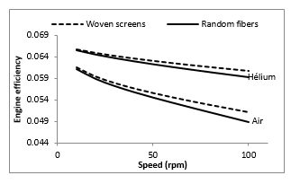 Figure 14: Engine efficiency for two regenerator types
5. Conclusion
In order to contribute to the development of LT-SE regenerators’ design, a calculation model was developed, validated and used to analyze the effect of six regenerator parameters in order to find out their optimized values. Studied parameters are: engine speed, regenerator volume, regenerator porosity, regenerator wire diameter, working fluid type and regenerator fibers arrangement. Results indicated a number of optimization recommendations of LT-SE:
- Low speed is preferred in order to reduce the pressure drop and to enhance the heat exchange in regenerator;
- A regenerator length around Lreg should be adopted, where :
Lreg= 1.41 x diplacer stroke
- The optimal value for wire diameter is: dw=0.15mm, corresponding to a hydraulic diameter dh=0.45mm;
- Porosity of the regenerator matrix should have a moderate value (β= 0.75);
- The most performant working fluid is helium. However, because of the recurring sealing problems on Stirling engine performance, the use of air is most adequate (available and for free);
- The use of woven screens regenerators is not necessary for engines running at low speed (<50rpm), random fibers give acceptable performance. At higher speed, woven screens regenerators are more suitable, giving better engine efficiency.
By following the guidelines presented in this paper, an appropriate configuration for LT-SE can be selected.
Nomenclature
| Parameter | Signification- Unit | ||
| A | Section area of the regenerator housing (m2) | ||
| Awg | Wetted area (m2) | ||
| Cp | Specific heat of fluid at constant pressure (J/kg K) | ||
| dh | Hydraulic diameter (m) | ||
| dw | Wire diameter (m) | ||
| f | Darcy Friction factor (-) | ||
| h | Convective heat transfer coefficient (W/m2 k) | ||
| k | Thermal conductivity (W/mK) | ||
| Lreg | Regenerator length (m) | ||
| Nu | Nusselt number (-) | ||
| NTU | Number of transfer units (-) | ||
| Pe | Peclet number (-) | ||
| Pr | Prandtl number (-) | ||
| Qm | Mass flow rate (kg/s) | ||
| Qperte
Re |
Heat lost due to regenerator imperfection (J) | ||
| Reynolds number (-) | |||
|
Specific gas constant (J/kg K) | ||
| Tc, Tf | Absorber a cooler temperatures respectively | ||
| Tr | Regenerator temperature | ||
| u | Fluid velocity (m/s) | ||
| Vc | Expansion volume | ||
| Vf | Compression volume | ||
| Vmc | Dead volumes in the absorber side | ||
| Vmf | Dead volume in the cooler side | ||
| Vmtr | Dead volume in the working space | ||
| Vsc | Maximal volume of hot space | ||
| Vstr | Maximal volume of working space | ||
| VR | Regenerator volume | ||
| Vtr | Working space instantenous volume | ||
| Greek symbols | |||
| α | Phase angle (°) | ||
| β | Porosity (-) | ||
| θ | Flywheel angle (°) | ||
| ρ | Density (kg/m3) | ||
| ε | Regenerator efficiency (-) | ||
| μ | Dynamic viscosity (kg/ms) | ||
| η | Engine efficiency (-) | ||
Conflict of interest
The authors declare no conflict of interest.
- R.Stirling, Stirling air engine and the heat regenerator, Patent no, 4081, 1816.
- K.Wang,S.R. Sanders, S. Dubey, F.H. Choo, F. Duan, “ Stirling cycle engines for recovering low and moderate temperature heat: A review” Renew. Sustain. Energy Rev., 62, 89–108, 2016. https://doi.org/10.1016/j.rser.2016.04.031
- C. Toro, N. Lior, “Analysis and comparison of solar-heat driven Stirling, Brayton and Rankine cycles for space power generation” Energy, 120, 549–564, 2017. https://doi.org/10.1016/j.energy.2016.11.104
- S K. Andersen, H. Carlsen, P.G. Thomsen, “Numerical study on optimal Stirling engine regenerator matrix designs taking into account the effects of matrix temperature oscillations” Energy Convers. Manag. , 47, 894–908, 2006. https://doi.org/10.1016/j.enconman.2005.06.006
- L. Sun, T.w. Simon, S. Mantell, M. Ibrahim, D. Gedeon, R. Tew, “Thermo-fluid experiments supporting microfabricated regenerator development for a Stirling spacepower engine”, in 2009, 7th International energy conversion engineering conference, Denver, Colorado 2009. 10.2514/6.2009-4579
- W. Kays, A. London, Compact Heat Exchangers.,New York: McGraw-Hill, 1984.
- J.R. Sodré, J.A. R. Parise, “Friction Factor Determination for Flow Through Finite Wire-Mesh Woven-Screen Matrices” J. Fluids Eng., 119, 847–851, 1997. https://doi.org/10.1115/1.2819507
- M. Tanaka, I. Yamashita, F. Chisaka,”Flow and heat transfer characteristics of the stirling engine regenerator in an oscillating Flow” JSME Int. J., 33, 283–9, 1990. https://doi.org/10.1299/jsmeb1988.33.2_283
- S. Alfarawi, R. Al Dadah, S. Mahmoud, “Potentiality of new miniature- channels Stirling regenerator”, Energy convers. Manag., 133-264, 2017. https://doi.org/10.1016/j.enconman.2016.12.017
- I. Rühlich, H. Quack , New regenerator design for cryocoolers, Technische Universiat, Dresden,1999.
- D. Gedeon, J. Wood, Oscillating-flow regenerator test rig: hardware and theory with derived correlations for screens and felts, NASA CR (N°198442), 1996.
- MB. Ibrahim, T. Simon, D. Gedeon, R. Tew , ”Improving performance of the Stirling converter: redesign of the regenerator with experiments”, Computation and modern fabrication techniques, Cleveland State University, 2001.
- MB. Ibrahim., Danila, D., Simon, T.W., Gedeon, D., Tew, R. , “Computational Modeling of a Segmented-Involute-Foil Regenerator for Stirling Engines” J. Thermophys. Heat Transf., 23, 786–800, 2009. https://doi.org/10.2514/1.40330
- R. Tew , R. Dyson, S.D. Wilson, R. Demko. , Stirling convertor CFD model development and regenerator R&D efforts, in December 2004, In 2004, AIP Conference Proceedings 746,NASA, 2004. DOI: 10.1063/1.1867183
- Anders S. Nielsen, Brayden T. York, Brendan D. MacDonald, “ Stirling engine regenerators: How to attain over 95% regenerator effectiveness with sub-regenerator and thermal mass ratios”, 253, Applied Energy, 2019. https://doi.org/10.1016/j.apenergy.2019.113557
- K.V. Srinivasan, A. Manimaran, M. Arulprakasajothi, M.Revanth, Vijay A. Arolkar, “Design and development of porous regenerator for Stirling cryocooler using additive manufacturing” Therm. Sci. Eng. Prog. , 11, 195-203, 2019. https://doi.org/10.1016/j.tsep.2019.03.013
- N. Boutammachte, J. Knorr, ”Field-test of a solar low delta-T Stirling engine” Sol. Energy, 86, 1849–1856, 2012. https://doi.org/10.1016/j.solener.2012.03.001
- H. El Hassani, N. Boutammachte, M. Hannaoui, “Study of some power influencing parameters of a solar low temperature Stirling engine”, European Journal of Sustainable Development, 3(2), 109-118. http://dx.doi.org/10.14207/ejsd.2014.v3n2p109, 2014.
- R. Gheith, F. Aloui , S. Ben Nasrallah, “Study of temperature distribution in a Stirling engine regenerator”, Energy Convers. Manag., 88, 962-972, 2014. https://doi.org/10.1016/j.enconman.2014.09.043
- K. Hirata, I. Iwamoto, K. Hamaguchi, “Performance evaluation for a 100 W Stirling engine” in 1997 8th International Stirling engine conference, University of Ancona, Italy, 19–28, 1997.
- S. Wilson, R. Dyson, R. Tew, R. Demko, Experimental and computational analysis of unidirectional flow through Stirling engine heater head”. Nasa center for aerospace information, 2006.
- D. Berchowitz, I. Urieli, Stirling Cycle Machine Analysis. Adam Hilger, 1984.
- H. El Hassani, N. Boutammachte, J.Knorr, M. Hannaoui, “Study of a low-temperature Stirling engine drivenby a rhombic drive mechanism”, Int. J. Energy Environ. Eng., 4, 40-50, 2013. https://doi.org/10.1186/2251-6832-4-40
- D. Chen, “Untersuchung zur Optimierung eines solaren Niedertemperatur-Stirlingmotors”, Ph.D Thesis, Technischen Universität Dresden, 2004.
- H. El Hassani, “ Etude théorique et expérimentale des paramètres régissant le fonctionnement des moteurs Stirling à basse temperature”, Ph. D Thesis, Moulay Ismail University, 2014.
- I. Kolin, Stirling Motor: History- theory- practice, Dubrovnik- Zagreb University Publications, 1991.