System of Sequential D-Optimal Identification for Dynamic Objects in Real-Time Scale

Adv. Sci. Technol. Eng. Syst. J. 5(2), 211–214 (2020);
 DOI: 10.25046/aj050227
The article is devoted to the formalization and development of the theory of sequential experimental design for optimal identification of dynamic objects. The algorithmic and technical support for a system of sequential D-optimal identification for a wide class of dynamic objects in real time is considered. This system is universal and can be used for optimal identification of real objects and continuous technological processes.
1. Introduction
This paper is an extension of work originally presented in 8th Mediterranean Conference on Embedded Computing (MECO) [1].
The construction of adequate models of the dynamic objects under study is an important step in solving any applied task. With a known or given structure of the dynamics model, the problem of experimental statistical parametric identification is usually solved. The quality of the resulting dynamic regression model (DRM) is determined by the probabilistic properties of the estimates for the unknown model parameters and its predictive properties.
If active influence at the input of the object is allowed, then the optimal parametric identification task can be formulated and solved, the purpose of which is to obtain an optimal dynamic regression model that satisfies the selected criterion.
The most universal optimality criteria used in the design of the experiment are the equivalent D- and G-optimality criteria, which simultaneously minimize the generalized variance of estimates for unknown model parameters and the maximum in terms of planning space variance of the output prediction according to the regression model [2-5].
When constructing dynamics models satisfying these criteria, it becomes necessary to formalize and solve additional problems:
- synthesis of optimal test signals [1, 4-11];
- technical implementation of optimal identification procedures in real time, which is especially important.
As a rule, DRMs have a nonlinearly parameterized structure. Therefore, their optimal identification is possible on the basis of the theory of sequential design of the experiment [2, 3], adapted to the problems of dynamics. Based on this theory, an original procedure of sequential D-optimal identification (DPPI) [1, 5-9] was developed, which allows us to study a wide class of linear and nonlinear dynamic objects described by input-output models and state spaces. Thus, the scientific novelty of this study lies in the development for the classical theory of experimental design and the development of methodology. Algorithmic and technical support of the original real-time control systems with optimal identifying studies of a wide class of dynamic objects.
2. Short description of DPPI
Let’s Consider the class of dynamic objects described by regression models, represented in the form:
where – is the vector of unknown parameters of the dynamic regression model; – discrete value of the output of the object.
As the factors of planning discrete values of input signal are accepted:
DPPI is implemented in real time as follows.
At the time of starting the system, an arbitrary non-degenerate “seed” test signal is supplied to the input of the identifiable object through the actuator, the implementation of which determines the initial NLSM estimate of the vector of unknown model parameters and its covariance matrix. These data are used in planning the first stage of the procedure. When planning the next stage, the NLSM estimation and its covariance matrix are used, obtained from the results of all previous stages, including “seed” testing. The planning goal is to synthesize a part of the local D-optimal plan, which implies one or more planned exit measurements at the planned stage of the procedure. The choice of the number of planned measurements of the output is carried out on the basis of effectiveness criterion for the implementation of the procedure, taking into account the cost per unit of testing time, the cost of one measurement of the output, as well as the sensitivity function of the dispersion function of the DRM to estimates of unknown model parameters.
Each point of the plan corresponds to a piece of piecewise-constant testing signal, which must be implemented at the input of the object before the moment of the planned measurement of the output. The continuity of the test signal is ensured by “sewing” sections on γi clock cycles according to the algorithm:
where i– is the number of the sector.
If it is more efficient to plan several exit measurements at the stages of DPPI, then the synthesis of part of the local D-optimal plan implemented at the (N+1) – th stage is carried out according to the algorithm:
where – is i-th point of the part of the local D-optimum plan, defining (N+1)-th stage of DPPI; – covariance matrix of vector , if to specify it due to the results of i planned measurements of the output on (N+1)-th stage.
The implementation of DPPI ends at the stage in the planning of which the difference between the locally optimal plan synthesized in parts and the D-optimal one will become insignificant:
where q – is the number of unknown parameters of model; – is dispersion of random output component; ε – a priori set small value.
Planning for the next stage begins from the moment the previous stage is completed. Therefore, it is relevant to minimize the planning time, which depends on the characteristics of the optimization and estimation algorithms used, as well as using the sequence of implementation for the plan points when constructing the test signal, taking into account the need for its level to remain constant over the planning interval.
A detailed algorithm for the implementation of DPPI is given in [1].
3. Description of the system architecture
A DPPI implementing system should consist of the following elements:
- Calculation Computer;
- programmable logic controller (PLC);
- sensors for measuring the output parameters of the identified object;
- actuators for realization of test signals.
The main functions implemented by the computer calculation computer [3-6,11]:
- planning of the DPPI stages;
- determination of discrete values for sections of minimum length testing signals and moments of planned output measurements.
- control of time instants for planned output measurements. At times when it is required to take data, the calculator issues a request for the programmable controller. It is supposed to use Ethernet as a communication port.
Functions implemented by the PLC:
- data collection from sensors of identifiable object output variables at planned time points;
- transfer of this data to the calculation computer for subsequent registration and processing. A diagram of the computing complex for solving problems of D-optimal sequential identification in real time is shown in [1]
The block diagram of a system of D-optimal sequential identification in real time is given in [1].
4. Calculation Computer
The software of the calculation computer implements 4 processes:
- the process of implementing the procedure of sequential D-optimal identification.
- the process of data requesting from the PLC;
- process of creating a control signal for actuator;
- scheduling process.
At each stage of the D-optimal identification procedure, the time moments of the change in the signal levels of the control action determining the piecewise-constant testing signal, and the moments of requesting data from the output of the object are determined, which leads to the execution of processes 2 and 3.
The process of requesting data from the PLC occurs according to the following algorithm. At times when it is necessary to request data from the PLC, the software of calculation computer transfers the high execution priority to this process. A data request begin. After sending the request, the program will wait for a response of 100 ms. If no response is received, another request will be made. After 3 failed exchanges in a row, the program will end with an error. If the data was received, they will be written to shared memory [12] for process of sequential D-optimal identification. After completing this process, the software will block it until the next moment in time for requesting data from the PLC.
Exchange with the PLC will occur via Modbus TCP protocol. This is a modification of the MODBUS protocol for working in tcp/ip networks. Modbus is based on the Master-Slave architecture, where in this case the calculation computer will be the master, and the PLC will be the slave responding to requests.
The process of creating a control signal for actuators operates as follows. At times when it is necessary to change the testing signal, execution priority will be given to this process. A signal will be sent to the control device. After completing this process, the software will block it until the next moment in time of changing the level of the test signal.
During the operation of the software, it may turn out that the execution times of processes 2 and 3 may coincide, which may lead to the fact that one of these processes will not be completed in time. To eliminate this, process execution is spaced on different processor cores.
Fig. 1 shows how priorities are allocated and, accordingly, when the implementation of the corresponding process begins
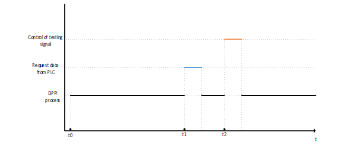 Figure 1: Prioritization of the processes of the calculation computer by time.
Fig. 1 shows that from time t0, which is the conditional start of the software, the high priority is always given to the process of implementing the sequential D-optimal identification procedure. The time instants t1 and t2 correspond to the time instants calculated during the planning phase of the DPPI.
Due to the fact that processes must be launched at certain points in time, it is required to implement another process that will monitor the execution time of the rest – the scheduler. The reason for its creation is that the RTOSs do not have their own software timers, and standard functions can lead to time fluctuations[12,13]. That why, own software timer needed to create. By using this timer, the scheduler will issue commands to transfer control to the processes described above.
5. Programmable logic controller
PLC is a device that works in cycles and performs two main functions
- inputs polling;
- execution of a user program that records the data received at the inputs and further transfers this data via Ethernet to the computer at the scheduled times.
To ensure high system reliability, it is required that the PLC respond to requests from the computer with high speed. This is achieved by the fact that:
- PLC provides a high frequency of data acquisition from sensors (estimated value of 100 Hz);
- The PLC, having received a request from the calculator at the scheduled time, instantly sends the last received data to the calculator.
PLCs are equipped with both discrete and analog inputs, which allows you to take data from the corresponding sensors without the use of additional equipment, such as analog-discrete converters. Data received from the PLC to the computer will be written to the data log file.
Most PLCs, in terms of receiving information, work with the MODBUS protocol based on the Master-Slave architecture [14-16], where the master is the PLC itself, while the slaves are surveyed sensors. The master initiates exchanges by sending requests. Such exchanges can be both individual and broadcast for all slave devices. The slave device responds to a request addressed to it. Upon receipt of a broadcast request, a response by slaves is not generated.
PLC connection to the object under study depends on the sensor, with which you can measure the output parameter of interest to us. Most often, these sensors have RS-485 and RS-232 communication lines, which will require analog ports and Modbus RTU protocol. Sensors operating over the Ethernet communication line are increasingly appearing. Such devices will require an Ethernet router, and the PLC will operate using the Modbus TCP protocol. In both cases, to receive data from sensors, PLC send request with the command 0x03 – registers reading [16].
In addition, PLC can be used as actuator, thanks to the presence of discrete inputs and outputs. The control is implemented as follows: the Calculation Computer sends a discrete output write command to the PLC – 0x05; when recording a discrete output, 2 values 0 and FF are used; Having accepted the command, the PLC, depending on the setting, will create a control action. The control action can be of two types:
- By analogue output. In this case, the numerical value of the test signal will be sent to the device for changing the input parameter. u1 for 0 and u2 for FF;
- By discrete output. In this case, the PLC sends a pre-programmed value received from the calculation computer to the actuator of the object
The algorithms for data request by the calculation computer and the operation of the PLC are given in [1].
The features of the technical implementation of DPPI for the identification of the reaction process of methanol and oxygen for the production of formaldehyde are considered in [1].
The developed system is universal and can be used for optimal identification of continuous technological processes in various industries.
Conflict of Interest
We declare there is no conflict of interest.
Acknowledgment
TSU (Tula state university), Tula, Russian Federation.
- Fatuev V.A., Mishin A.A. Realization of Optimal Identification Tasks for Dynamic Systems in Real Time Scale. 2019 8th Mediterranean Conference on Embedded Computing (MECO), 2019, pp. 537-540. DOI: 10.1109/MECO.2019.8760138
- Fedorov V.V. Teoria optimalnogo experimenta [Theory of optimal experiment], Moscow, Science, 1971, 312 p.
- Krug G.K., Fatuev V.A. Synthesis of D-optimal testing signal for one class of dynamic objects. Avtomatika i telemekhanika [Automation and Remote Control], 1974, no. 8, 73-77. (In Russia)
- Krug G.K., Fatuev V.A. Synthesis of D-optimal testing signal for one class of dynamic objects. Avtomatika i telemekhanika [Automation and Remote Control], 1974, no. 8, pp. 73-77. (In Russia)
- Fatuev V.A. Optimalnaya identifikaciya i upravlenie dinamicheskimi sistemami. Ucheb. posobie [Optimal identification and management of dynamic systems. Allowance]. Tula, 2019. 120 p.
- Fatuev V.A., Khrapova A.G., Morozova A.N. Algorithmic ensuring realization of serial procedure D-optimal identification in real time. Izvestiya TulGU. Tekhnicheskie nauki [News of TSU. Technical science]. 2014, no. 11. part 2. pp. 612 – 620. (in Russia)
- Fatuev V.A., Mishin A.A. Control of the experiment with optimum identification of dynamic systems in real time. 2018 7th Mediterranean Conference on Embedded Computing (MECO). 2018. pp.1-4. DOI: 10.1109/MECO.2018.8406057
- Fatuev V.A., Mishin A.A. Algorithmic and technical ensuring for the implementation of the procedure for optimal identification of dynamic system in real time scale. Izvestiya TulGU. Tekhnicheskie nauki [News of TSU. Technical science]. 2018, no. 12. part. pp. 315-323. (in Russia)
- Bahvalov L.A. On a problem of input signal synthesis on the statistical identification of linear dynamic systems. Tekhnicheskaya kibernetika [Technical Cybernetics]. 1974, no. 3. 191-196. (in Russia)
- Boroduk V.P., Kirichenko A.V. Constructing the optimal input signal to identify multichannel dynamic objects. Trudy MEI [Works of MEI] 1975, no. 241. pp. 30 -36. (in Russia)
- Oslender D.M., Ridgeley J.R., Ringenberg J.D. Upravlayushie programmi dlya mekhanicheskih sistem:obyektno-orientirovannoe proektirovanie sistem realnogo vremeni [Control programs for mechanical systems: Object-oriented design of real-time systems], Moscow, 2004, 416 p.
- Burdonov I.B., Kosachev A.S., Ponomarenko V.N. Operacionnie sistemi realnogo vremeni [Real-time operating systems], Moscow, 2006, 98 p.
- Burdonov I.B., Kosachev A.S., Ponomarenko V.N. Operacionnie sistemi realnogo vremeni [Real-time operating systems], Moscow, 2006, 98 p.
- Minaev I.G., Sharapov V.M., Samoylenko D.G. Programmiruemie logicheskie kontrolleri v avtomatizirovanih sistemah upravlenia [Programmable logic controllers in automated control systems], Stavropol, 2010, 128 p.
- Parr E. Programmiruemie kontrolleri: rukovodstvo dlya ingenera. [Programmable Controllers: Engineer’s Guide], Moscow, 2007, 516 p.
- Modicon modbus protocol reference guide – North Andover, 1996 – URL: http://modbus.org/docs/PI_MBUS_300.pdf
No related articles were found.