
Control of Electrostatic Suspension System Using Pulse Width Modulation
Volume 5, Issue 2, Page No 204-210, 2020
Author’s Name: The Truyen Lea)
View Affiliations
Department of Mechanical Engineering of Ho Chi Minh City University of Food Industry, 140 Le Trong Tan Street, Ho Chi Minh City, 760310, Viet Nam
a)Author to whom correspondence should be addressed. E-mail: truyenlt@cntp.edu.vn
Adv. Sci. Technol. Eng. Syst. J. 5(2), 204-210 (2020); ![]() DOI: 10.25046/aj050226
DOI: 10.25046/aj050226
Keywords: Electrostatic suspension system, Pulse width modulation, Silicon wafer

Export Citations
Electrostatic suspension systems have great potential applications in contactless transportation objects since they allow many different materials to be suspended. The electrostatic suspension will be widely applied in practice if the system cost is inexpensive. This paper presents an electrostatic suspension system controlled by using pulse width modulation (PWM). The use of PWM in electrostatic suspension system will reduce the system cost since inexpensive switching power amplifiers could be applied instead of linear analogue power amplifiers, which are bulky and costly. The simulation and experimental results are performed and showed that PWM can be used effectively to control the position of the levitated object in the electrostatic suspension.
Received: 31 January 2020, Accepted: 02 March 2020, Published Online: 13 March 2020
1. Introduction
The electrostatic suspended actuation can be used in a special environment without problems caused by friction, abrasion or lubrication. The electrostatic suspension systems can levitate many different materials without any contact, therefore, they are useful in micro-bearings, contactless levitation and transportation of silicon wafers [1, 2], aluminum hard disks media [3] and glass panels [4]. The electrostatic suspension systems could be also used effectively for the process of handling materials. Generally, the material handling process requires containers containing the material processed. However, if the melting point of material treated is higher than that of the material of container, this handling process becomes difficulty. The contactless levitation performed by the electrostatic suspension system can help this handling process perfectly performs since it is devoid of using any container for handling materials.
Generally, electrostatic suspension systems require several kV voltages to create enough electrostatic force for the suspension process. So, the traditional electrostatic systems use the high analogue voltage amplifiers to amplify the low output voltage signals of the feedback controller. However, these devices are very cumbersome, especially they are expensive components [5-7]. Moreover, electrostatic suspension system requires many electrodes to suspend wide flexible objects result in an increase in the number of these devices. This leads to an increase in the cost of the suspension system and it hinders the widespread application of electrostatic suspension in practice [8]. Therefore, it is necessary to develop the low-cost contactless electrostatic suspension systems to improve its applicability in practice.
Modulation technique is widely applied in many industrial fields, however, this method has not been successfully applied in the field of contactless suspension by electrostatic forces. The use of modulation techniques in this field is attractive because it allows employing the inexpensive switching power amplifiers instead of expensive analog high voltage amplifiers.
Many modulation techniques such as integral pulse frequency modulated [9], pulse width modulation [10], and pulse width pulse frequency modulation [11] are applied in industrial systems. Among them, PWM is widely used because it has many advantages such as robust against disturbances and easily implemented. It could be found application of PWM in motor controls [12], pneumatic and hydraulic actuators [13-14], shape memory alloy actuator [15, 16], 3-RPR parallel robot [17], pneumatic valves [18, 19], Electro-Mechanical Actuator [20], and in piezo air jet actuators [21]. This paper introduce a contactless suspension system by using modulation techniques. In this paper, the PWM is used to modulate an PID controller (Proportional-Integral-Derivative) in order to control the position of the suspended object. Experimental results prove that the contactless suspension by electrostatic forces could be implemented by using the PWM-modulated PID controller. The system provides an accurate position control with an inexpensive switching power amplifier.
2. Experimental setup
The schematic of 1 d.o.f (degree of freedom) contactless suspension system by electrostatic force is introduced in Fig. 1. The external disturbance forces Fext is small and it is ignored. Thus, the dynamic motion of the object could be presented by [22]:
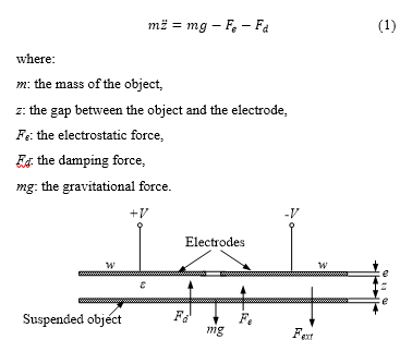 Figure 1: The schematic of 1 d.o.f contactless suspension system by electrostatic force
The electrostatic can be expressed as [22]:
 in which,
V: the supplied voltage,
e : the permittivity of the air, its value is 8.854e-12 F/m
A: the area of electrode.
Equation (2) reveals that the supplied voltage V must be controlled for the stabilization of the levitated object.
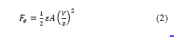
The schematic and experimental system used to perform the contactless suspension are presented in Fig. 2. The electrostatic suspension system using PWM consist of four major components: stator electrodes, position sensors, and circular shaped suspended object (4-inch silicon wafer). The process of contactless levitation of the object (4-inch silicon wafer) needs to be controlled in five degree of freedoms that are the horizontal plane, vertical movement, pitching, and rolling [23]. However, the displacements of the object in the horizontal plane are passively balanced without any active control due to the regenerative force created by the edge field that will pull the object back into position where object and electrode overlap.
The remaining three degrees of freedom that are rolling, pitching and vertical displacements must be balanced by the active control of the force acting on the object [22]. This could be performed by using three fan shape electrodes that are directly positioned above the object. Each electrode is designed to include an external electrode Eip and an internal electrode Ein, (i=1, 2, 3). The positive voltage provides to the external electrode, and the negative voltage supply to the internal electrode. Three external electrodes are arranged in a circle with the same diameter of the object [8]. Three position sensors are placed in the center hole of each electrode #1, #2 and #3 to detect positions of suspended object, respectively. The electrode surface is covered with an insulating layer with a thickness of 80 µm to prevent short circuits if the suspended object comes in contact with electrodes.
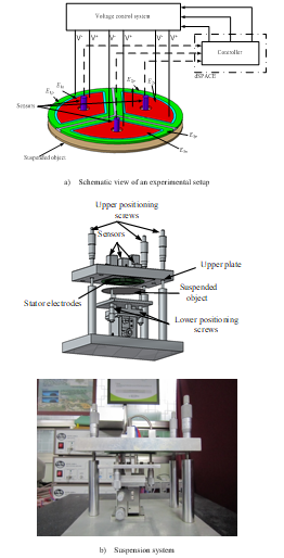 Figure 2. Experimental apparatus [22]
 Figure 3. Stator electrodes
Contactless suspension of a suspended object is performed by using a controller implemented by using dSPACE data acquisition system. The design of controller is described in section 3. The position of the object is detected by the position sensors, and the position signal is fed to the controller. The voltage supplied to the electrode will occur in an on-off action according to the position sensor signals by the switching circuit. The switching power amplifier provides the charged voltage and discharged voltage to the external and internal electrode Ep and En parts of each electrode, respectively. The switching power circuit is designed by using power metal-oxide-semiconductor field-effect transistor (MOSFET). For controlling MOSFET, the drive chip IR2104 is employed. The switching power amplifier circuits are presented in Fig. 4.
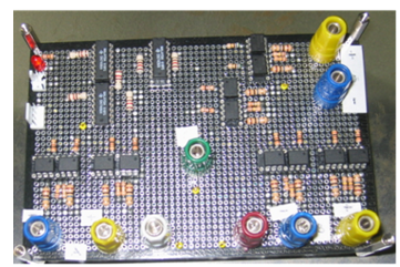 Figure 4. The switching power amplifier circuits
3. PWM-PID controller designed for the electrostatic suspension system
The mechanisms implement of PWM in this paper is presented in Fig. 5. It includes of a triangular carrier wave with a constant frequency r(t) and a bang-bang trigger [13]. It notes that the amplitude of carrier ware is greater than the greatest amplitude of the control signal. The difference e(t) between the control signal and the carrier wave is fed to the bang-bang trigger. The value of e(t) will determine the bang-bang trigger outputs that are Ac or –Ac. Namely, the bang-bang trigger output is Ac corresponding to the on-state if the value of e(t) is positive and bigger than the bang-bang trigger threshold, otherwise, its output is –Ac corresponding to the off-state. The bang-bang trigger will change state twice in a cycle since the carrier wave is triangular. The pulse width is equal to the times during the value e(t) is bigger than the bang-bang trigger threshold. Thus, the frequency of the pulse generated is the same as the carrier wave and its amplitude is constant.
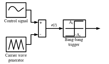 Figure 5. The mechanisms to implement PWM
Figure 6 describes in detail of mechanism to implement a modulated pulse with a triangular carrier wave r(t), the bang-bang trigger threshold, in that case, is equal zero, where Tc and 2Ar are called the period and amplitude of carrier wave r(t), respectively.
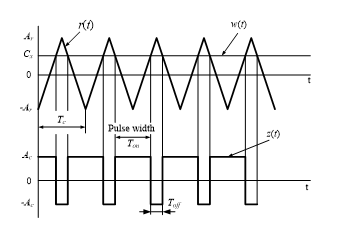 Figure 6. A mechanism implement of the modulated pulse
If the input values are constant then the mean time of output value is given by [13]:
![]() where is the mean time of z(t), and is the mean time of w(t) for the period of Tc.
where is the mean time of z(t), and is the mean time of w(t) for the period of Tc.
Equation (3) reveals that the mean time of the PWM output is proportional to the because the ratio Ac/Ar is a constant and it does not depend on time. In other words, the pulse width is directly proportional to the control signal amplitude.
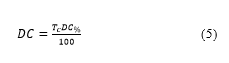
Ton is called the on-time or PW and it is the time required for the bang-bang trigger output moves from value Ac to –Ac. Otherwise, the time required for the bang-bang trigger output moves from –Ac to Ac called the off-time, Toff. The duty cycle (DC) of the PW modulated is equal the percentage of the on-time to the period and is presented by [13]:
 Equation (3) also reveals that the output is approximately proportional to the , therefore, if the input signal w(t) is a time varying then the frequency of input signal must be large enough to obtain the almost constant value of output [20].
In this paper, the controller that combines PID (proportional-integral-differential) and PWM are used to control the displacement of suspended object in the contactless electrostatic suspension system because this combination provides many advantages such as robust again disturbances and easily implemented. The idea is using PID controlling the PWM duty cycle. PID is well-known controller, and it is widely applied in many process control. This controller includes of three control terms that are proportional, integral and derivative term. The proportional term (KP) provides an control action proportional to the error signal. The integral term (KI) effects on the steady-state errors. The derivative term (KD) effects on the transient response [24].
The proper value of duty cycle is determined by PWM-PID controller as [16]:
 where , e is the error between the current position of suspended object and reference position.
The suspension system with 3 d.o.f is illustrated in Fig. 7. The suspended object is levitated by three independent stator electrodes. Each pair of electrode (E1p, E1n), (E2p, E2n) and (E3p, E3n) is supplied by control voltage accordingly to the corresponding sensor signals. The PWM converts the PID controller output into a pulse series between on-voltage (VON) and off-voltage (VOFF) with a duty cycle value between 0 and 100% which is determined by Eq. (5). As a result, the electrostatic forces F1, F2, and F3 generated by three pair electrodes (E1p, E1n), (E2p, E2n) and (E3p, E3n), respectively, are controlled.
4. Simulations and Experimental results
The suspended object (4-inch silicon wafer) with a radius of 50 mm, the thickness of 0.71 mm, and a mass of 9.1 g is used. The suspended gap is 320 µm, and the initial position of silicon wafer is set at 350 µm. Based on Eq. (2), the bias voltage is calculated as V0 = 480 V.
Therefore, the on-voltage (charged voltage) VON should be bigger than the bias voltage, was set at VON = V0 +50%V0, i.e. 780 V, the off-voltage (discharged voltage) VOFF was 0 V. The controller was implemented digitally in dSPACE system and three optical fiber position sensors used to measure the gap length (Model PM-E, Nanotex Co.). Figure 8 presents the control block diagram for the suspension system.
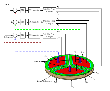 Figure 7. Control system of the 3 d.o.f electrostatic suspension system
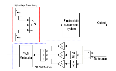 Figure 8. The PID-PWM control diagram for the suspension system
The gains of PID controller strongly influences on the performance of suspended object. Simulations are implemented to obtain the optimal values of the PID gains [24]. The simulation results in Fig. 9 reveal that steady state error reduced when PID gains are increased. The set of parameters of PID gains KP = 10e30, KD = 2000 and KI = 12e23 is chosen to apply in experiments.
Figure 10 shows a response plot performed experimentally. The object is suspended at a reference position with an amplitude of oscillation at the electrodes #1, #2 and #3 are around 0.9 µm, 1 µm and 1.2 µm, respectively. It is observed in Fig. 10 that the oscillation is very small. Figure 11 shows the applied voltages to electrodes during the suspension process.
Several electrostatic systems successfully apply the on-off controller to control the position suspended object such as simple on-off controller [7], delay controller [25], variable structure controller [8].
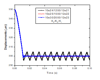 Figure 9. Simulation results of suspension
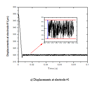
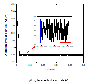
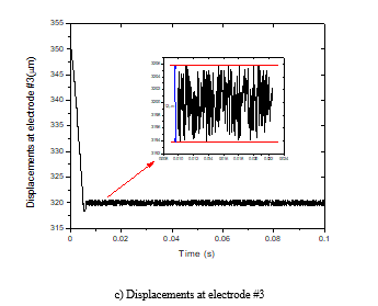 Figure 10. Displacements of the 4-inch silicon wafer during the suspension process
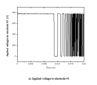
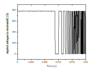
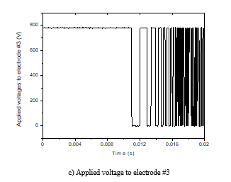 Figure 11. Applied voltages to electrodes during the suspension process.
Each of the above controllers has its advantages in each specific case. However, considering the parameters of the amplitude of oscillation, the PID-PWM controller has advantages compared to the remaining on-off controller. Comparison data of on-off controllers are presented in Table 1. The comparison shows that the electrostatic suspension system using PID- PWM controller provides a very good response with very small fluctuations of the suspended object.
Table 1: The amplitude of oscillation of several on-off controller
| Type of controller | Amplitude of oscillation |
| Simple on-off | ~ 6.5 µm |
| Delay controller | ~ 4.5 µm |
| Variable structure controller | ~ 2.3 µm |
| PID-PWM controller | ~ 0.9 µm |
Conclusion
This paper presents an electrostatic suspension system using PID-PWM controller. Simulation and experimental results reveal the effectiveness of this electrostatic suspension system. Application of pulse width modulation in electrostatic suspension system makes possible the use of inexpensive switching power amplifier instead of linear analogue power amplifier employed in previous systems, therefore, the system cost is reduced.
Conflict of Interest
The authors declare no conflict of interest.
Acknowledgment
The authors are very grateful for the support received from the University of Ulsan and Ho Chi Minh City University of Food Industry for this project.
- J. U. Jeon, J. Jin and T. Higuchi, “Electrostatic suspension of 8-inch Silicon wafer,” Proc. Inst. Electrosta. Japan, vol. 21, no. 2, pp. 62-68, 1997.
- J. Jin, T. C. Yih, T. Higuchi and J. U. Jeon, “Direct Electrostatic Levitation and Propulsion of Silicon Wafer,” IEEE Trans. Industry Applications, vol. 34, no. 5, pp. 975-984, 1998. DOI: 10.1109/28.720437
- J. Jin, T. Higuchi, and M. Kanemoto, “Electrostatic levitator for Hard Disk Media,” IEEE Trans. Industrial Electronics, vol. 44, no. 5, pp. 467 – 473, 1995. DOI: 10.1109/41.466330
- J. U. Jeon and T. Higuchi, “Electrostatic suspension of Dielectrics,” IEEE Trans. Industry Electronics, vol. 45, no. 6, pp. 938-946, 1998. DOI: 10.1109/41.735338
- J. Jin and T. Higuchi, “Direct Electrostatic Levitation and Propulsion,” IEEE Trans. Industrial Electronics, vol. 44, no. 2, pp. 234-239, 1997. DOI: 10.1109/41.564162
- E. West, A. Yamanoto and T. Higuchi, “Transportation of Hard Disk Media Using Electrostatic Levitation and Tilt Control,” IEEE Int. Conf. Robotics (ICRA), Pasadena, USA, pp. 755-760, 2008. DOI: 10.1109/ ROBOT.2008.4543296
- J. U. Jeon and S. Lee, “Electrostatic suspension system of silicon wafer using relay feedback control,” J. Korean society of Precision Engineering, vol. 22, no. 10, 56-64, 2005.
- T. Le, “A variable structure controller for a cost-effective electrostatic suspension system,” Transactions of the Institute of Measurement and Control, vol. 41, no. 2, 2019. https://doi.org/10.1177/0142331219826663
- R. N. Clark and G. F. Franklin, “Limit cycle oscillations in pulse modulated systems,” J. Spacecr. Rockets vol. 6, pp. 799–804, 1969. https://doi.org/10.2514/3.29704
- A. Kempski, R. Strzelcki, R. Smolenski and Z. Fedyczak Z, “Bearing current path and pulse rate in PWM-inverter-fed induction,” 2001 IEEE 32nd Annual Power Electronics Specialists Conf. (Vancouver, Canada) vol. 4 (Piscataway, NJ: IEEE) pp. 2025–2030, 2001. DOI: 10.1109/PESC.2001.954419
- T. C. Anthony, B. Wei and S. Carroll, “Pulse-modulated control synthesis for a flexible spacecraft,” J. Guid. Control Dyn. Vol. 13, no. 6, pp. 1014–22, 1990. https://doi.org/10.2514/3.20574
- L. Petrua and G. Mazenb, “ PWM Control of a DC Motor Used to Drive a Conveyor Belt,” Procedia Engineering, vol. 100, pp. 299 – 304, 2015. doi: 10.1016/j.proeng.2015.01.371
- M. Shih and M. Ma, “Position control of a pneumatic cylinder using fuzzy PWM control method,” Mechatronics, vol. 8, pp. 241–53, 1998. https://doi.org/10.1016/S0957-4158(98)00005-1
- M. M. Gade and K. K. Mangrulkar, “Modeling and PWM Control of Electro-Pneumatic Actuator for Missile Applications,” IFAC PapersOnLine vol. 51, no.1, pp. 237–242, 2018. https://doi.org/10.1016/j.ifacol.2018.05.057
- N. Ma and G. Song, “Control of shape memory alloy actuator using pulse width modulation,” Smart. Mater. Struct., vol. 12, pp. 712–719, 2003. https://doi.org/10.1088/0964-1726/12/5/007
- J. Ko, M. B. Jun, G. Gilardi, E. Haslam and E. J. Park, “ Fuzzy PWM-PID control of cocontracting antagonistic shape memory alloy muscle pairs in an artificial finger,” Mechatronics, vol. 21, pp. 1190–1202, 2011. https://doi.org/10.1016/j.mechatronics.2011.07.003
- S. A. Moezi, M. Rafeeyan, E. Zakeri and A. Zare, “Simulation and experimental control of a 3-RPR parallel robot using optimal fuzzy controller and fast on/off solenoid valves based on the PWM wave,” ISA Transactions, vol. 61, pp. 265-286, 2016.
- M. Pipan and N. Herakovic, “Closed-loop volume flow control algorithm for fast switching pneumatic valves with PWM signal,” Control Engineering Practice, vol. 70, pp. 114-120, 2018. https://doi.org/10.1016/j.conengprac.2017.10.008
- B Zhang, Q Zhong, Ji Ma, H Hong, H Bao, Y Shi and H Yang, “Self-correcting PWM control for dynamic performance preservation in high speed on/off valve,” Mechatronics 55 (2018) 141-150. https://doi.org/10.1016/j.mechatronics.2018.09.001
- Y. Peng, Y. J. Zhang, D. T. Liu and L. S. Liu, “ Degradation estimation using feature increment stepwise linear regression for PWM Inverter of Electro-Mechanical Actuator Microelectronics,” Reliability, vol. 88–90, pp. 514–518, 2018. https://doi.org/10.1016/j.microrel.2018.06.025
- Y. Zhao and B. Jones, “Pulse width modulated reinforced piezo air jet actuators,” Mechatronics, vol. 7, no. 1, pp. 11-25, 1997. https://doi.org/10.1016/S0957-4158(96)00040-2
- T. T. Le, J. U. Jeon1, S. J. Woo and T. Higuchi, “An electrostatic suspension system using piezoelectric actuators,” Smart Mater. Struct., vol. 21 (2012) 025012 (8pp).
- T. T. Le and J. U. Jeon, “Stability analysis of a time-optimally controlled electrostatic suspension system and suspension experiments in a vacuum,” Proc. IMechE Part C: J. Mechanical Engineering Science, vol. 225, pp. 88-100, 2010. https://doi.org/10.1243/09544062JMES1925
- K. H. Ang and G. Chong, “PID Control System Analysis, Design, and Technology,” IEEE Transactions on control systems technology, vol. 13, no. 4, pp. 556-576, 2005. DOI: 10.1109/TCST.2005.847331
- T. T. Le and J. U. Jeon, “Time Delay Effects on Performance and Stability of a Low Cost Electrostatic Suspension System,” International journal of precision engineering and manufacturing, vol. 11, no. 4, pp. 549-557, 2011. https://doi.org/10.1007/s12541-010-0063-7