Hybrid Solar Thermal/Electricity Automated Oven

Adv. Sci. Technol. Eng. Syst. J. 5(2), 188–196 (2020);
 DOI: 10.25046/aj050224
This paper presents hybrid solar thermal/electricity automated oven. The work compares sliding mode control (SMC) to traditional PID control of the oven system using MATLAB/Simulink 2014b model. SMC control method shows faster rise and settling time. The control technique has been designed to automate change of temperature level of the oven by accepting multiple reference inputs. This has been implemented using microcontroller programed in C++. Flat-plate solar thermal collector and paint curing oven have also been implemented for experimental test. The results obtain from the experiments are in conformity to the simulation results. The collector delivers 43.27% of the total energy required to operate the oven up to 120°C at 200W/m2 solar insolation. Calculation of payback period for commercial viability on the cost of the collector installation indicates a year and four months for an average insolation of seven hours per day. These results demonstrate that the research work is effective and solves the problem of temperature control in curing modern organic paints and the challenge of power requirements in the operation of oven.
1. Introduction
This paper is an extension of work originally presented in 2019 IEEE International Conference on Sustainable Energy Technologies and Systems (ICSETS) [1].
Precise temperature control of ovens is very essential to industries and firms that use them for productions. Paint curing for instance involves converting applied wet or powdered paint to dry and hard film. Paint may cure by solvent loss, chemical reaction, oxidation, melting and re-solidifying, or melting and crosslinking [2]. It may take few hours for liquid paints to dry but it takes days to months to cure properly. To reduce cure time, paint curing ovens are used to speed up the process under elevated temperature, and energy is usually required for reliable and stable curing of industrial coatings [2, 3].
The primary challenges of curing and drying ovens generally are temperature control and energy optimization. Various temperature control methods such as traditional PID control system, Adaptive and Fuzzy Algorithm, fuzzy-PID control system, etc. [4, 5, 6] have been proposed in other works. Also, there are various methods energy can be made available to raise the temperature of oven and its content to required degree [7, 8]. The results obtained from the applications of these proposals show slow response time, delayed settling time, high overshoots and oscillations outside prescribed tolerance limits. Hence, they have not adequately met up with constraints in modern coatings and the complexity of curing ovens, especially when the different subsystems – heaters, air circulating fans, temperature sensors, etc. – have to work together to control temperature.
Moreover, as paint curing processes continue to improve, the tolerance limits have become much tighter from ±14°C in liquid-based paints to ±5.6°C in organic and powder paints [3, 9] which demands more robust control method that can track the set-point more accurately. On the other hand, Sliding Mode Control (SMC), a robust non-linear control method, has recently found wide applications to automatic control problems; largely due to its simple algorithm, order reduction, decoupling design procedure, disturbance rejection, insensitivity to parameter variations, simple implementation, high reliability and fast response [10, 11, 12].
The application of SMC to oven temperature control would provide the needed remedy since its comparison to the earlier mentioned control methods in other areas proved that SMC gives improved system performance [13, 14]. This work applies sliding mode control to paint curing oven temperature in other to overcome the inefficiencies of existing control methods. Sliding mode control (SMC), has many advantages and can track the desired temperature within limits. Solar thermal collector is incorporated to electric heating system for energy optimization.
2. Modeling and Simulation
2.1. Oven Modeling
Figure 1 is the block diagram model of energy flow in a convective oven system. The following assumptions were made in the modelling [15]:
- That all objects in the chamber are under thermal equilibrium condition.
- The materials that compose the oven and the work-piece have constant physical properties and do not depend on temperature.
- The heat capacity of insulators and supports of the oven are considered in the balance energy equation, where and m are the specific heat and the mass of each component in the oven respectively.
- The change of temperature T with respect to time, t has the following requirements:
- is maximum at t = 0, it is a non-increasing function of t and
- when .
- The energy of the chemical or phase transformation is neglect. It is assumed that no work enters or goes out from the oven
- It is considered that the cavity and both air and body surfaces place in it are in thermal equilibrium.
- The physical properties, as thermal conductivity and specific heat of oven components and work-piece materials, are constant.
- The temperature change in the inner part of the oven satisfies the following restrictions:
- .
- is small in the heating process.
- is maximum at t = 0, i.e., it is a decreasing function of t.
- When .
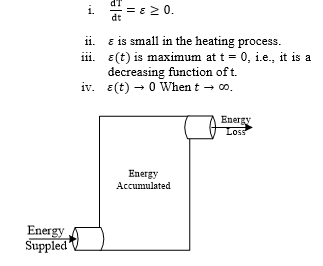 Figure 1: Convective oven energy flow model
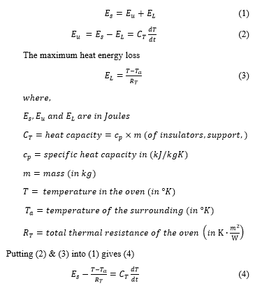
The energy supplied , to the convective oven is the sum of the accumulated energy and the energy loss .
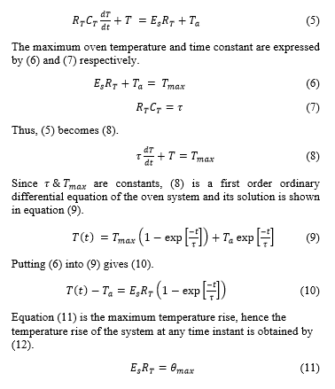
 Re-arranging (4) gives (5) which is the temperature evolution of the oven.
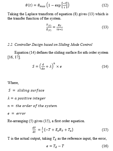
2.2. Controller Design based on Sliding Mode Control
Equation (14) defines the sliding surface for nth order system [16, 17].
Substituting for and into (14) gives (17).
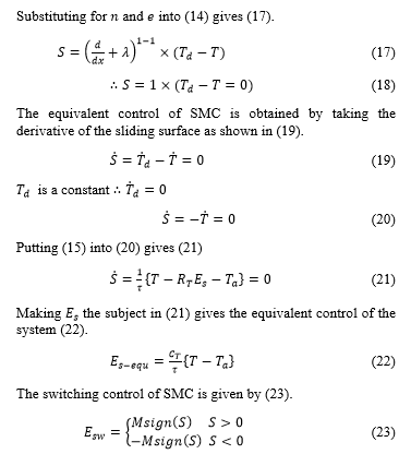 Where,
S is the sliding surface and
M is calculated based on Lipschitz function [18, 15].
SMC control law is given by (24).
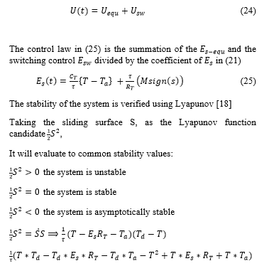
Since the highest power of the function is negative, ; therefore, the system is stable.
2.3. Simulation using MatLab/Simulink
Simulation of the oven system carried out in MATLAB/Simulink, as shown in the Simulink model description in Figure 2. The figure shows the reference temperature of 120℃ as the desired set-point. The reference is compared to the actual oven temperature from the feedback loop to generate error signal. The error e, is used by the sliding mode controller to generate commands that regulates the quantity of heat energy that is delivered to the oven chamber.
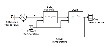 Figure 2: Simulink Model of SMC controlled Oven
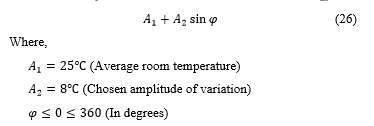
The SMC controller is a Simulink model sub-system designed using (25). The ambient temperature, is modelled in (26).
 The oven block is a Simulink model sub-system too. It is created using (13) which is the transfer function describing the oven system behavior. The oven temperature block is a scope that logs the temperature evolution in the oven.
The simulation is repeated after the SMC controller sub-system has been replaced with Simulink PID block for comparison.
2.4. Simulation Results
The simulation results for the SMC controller is shown as a plot of temperature against time in Figure 3. From the graph the controller drives the system temperature to rise continually until the reference temperature of 120℃ is reached. At steady-state the characteristic chattering effects of sliding mode controllers is seen as reviewed by a zoom-in of the plot. The highest and lowest peak of the chattering is ±0.3℃ which are within the tolerance limits of most of the sensitive materials that are baked in oven such as some organic paints that require ±5.6℃.
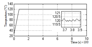 Figure 3: Plot of temperature vs time for SMC controlled oven
However, the simulation results after the SMC controller has been replaced by PID block shows high amplitude of oscillation at the steady-state region. The plot of temperature-time for the simulation is shown in figure 4.
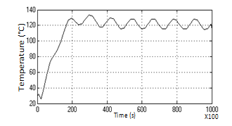 Figure 4: Plot of temperature vs time for PID controlled oven
The rise time for the PID controller is very long (11700s as against <100s for the SMC.
Table 1 shows comparison of further analysis results generated from Matlab tools like stepinfo command.
Table 1: Comparison of SMC and PID controller for oven
| Response | SMC Value | PID Value |
| Rise Time: | 98.39 (s) | 11700 (s) |
| Settling Time | 124.14 (s) | 64800 (s) |
| Settling Min | 119.709°C | 115.026 |
| Settling Max | 121.144°C | 133.36°C |
| Overshoot: | 0.9535% | 11.13% |
| Undershoot: | 0.2425% | 4.145% |
| Peak vale: | 121.144°C | 133.36°C |
Some important control factors have been compared as reviewed in Table 1.
- Rise time – this is the time taken for the system to rise from 10% of the steady-state value to 90% of the steady-state value (the steady-state value is ). From the analysis the SMC controlled oven has 98.39 s rise time while the PID controlled oven has a rise time of 11700 s.
- Settling time – this is the taken for the system to reach and remain within tolerance limits of steady-state value. The SMC controlled system has 124.14s and the PID controlled system has 64800 s to settle.
- Settling max and min – are the highest and lowest temperature values in the oven after the system has reached steady-state.
- Overshoot and undershoot – are the differences between the upper and lower limits of the system response and steady-state value expressed in percentage.
- Peak value – is the maximum temperature value attained inside the oven chamber.
The analysis results are evidence that the SMC controller performs better than PID controller for oven system. Hence, the system implementation is based on sliding mode control.
3. Implementations
3.1. Software Designs
The simulation results of sliding mode control of oven temperature in MATLAB/Simulink 2014b indicates that the control method is an improvement on the existing control methods in for oven temperature control. Three key implementations that have been designed and built to verify SMC oven control on a practical oven system; these are convective paint curing oven, flat-plate air solar thermal collector and sliding mode controller unit.
Figure 5 and Figure 6 are the screen captures of the AutoCAD drawings of the oven and the collector respectively. The dimensions of the oven are a height of 1200mm, a length of 900mm and breadth of 600mm. It also has 1000mm length and 400mm breadth door framing; exhaust air channel of 100mm x 100mm x 1000mm and insulation layer thickness of 50mm. Figure 5 shows control box that houses the controller, the keypad and display unit. Other things visible from the drawing are the power distribution box, the oven door lock and heater access door.
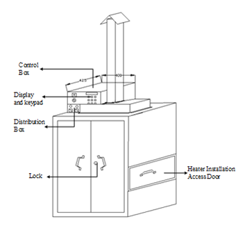 Figure 5: AutoCAD drawing of Convective paint curing oven
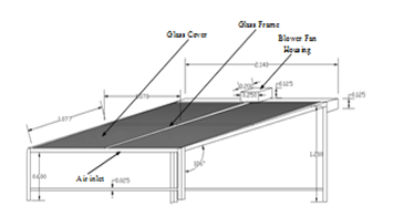 Figure 6: AutoCAD drawing of lat-plate air solar thermal collector
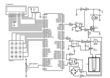 Figure 7: Proteus design of controller circuit diagram
Figure 6 shows 2140mm x 2140mm flat-plate collector tilted at 16° angle for higher reception of radiation since extraction is by air forced. The drawing shows the glass cover, glass frame, extraction fan housing and inlet air channel.
The design software is also used to generate the bill of materials (BOM), require for the implementation.
Figure 7 is screen capture of the control circuit diagram as designed in proteus software. It shows the microcontroller which is programmed using c++, a 16×2 LCD display, 3×4 matrix keypad electric heater control circuit and extraction fan controller for solar thermal collection.
3.2. Practical Implementation
The BOM generated from software is used to purchase the required materials need for the practical implementation. Figure 8(a) is a picture of the setup of the complete oven system with solar thermal collector and the control box. In the figure the chimney of the exhaust channel of can be seen on top of the oven and the control panel with the power distribution box mounted on the top left corner. The collector is place side by side with the oven and insulated host used to feed hot air extracted from the collector into the oven.
A zoom-in of the control box section is shown in Figure 8(b). It reviews the display, control box power switch, reset button, keypad and USB programmable port. The main power switches and fuse boxes are equally visible below the control box.
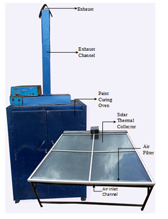 Figure 8(a): Picture of implemented system setup
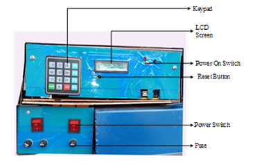 Figure 8(b): Picture of control box and power distribution box
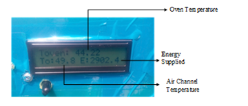 Figure 8(c): Picture of zoom-in display unit
Further zoom-in shown in Figure 8(c) is the real-time readings in the oven chamber as displayed by the LCD screen. They are the values obtained while the oven is powered by the solar collector alone. The value on top, Toven, is the temperature on the oven at the instant of taking the snapshot, the value at the lower left, To, is the temperature of the hot air extracted from the collector and the value at the lower right of the screen, E, is the total energy delivered by the collector.
3.3. Program Flow of the Controller – Automated Oven
The control implementation allows for setting two temperature levels of temperature reference points which the oven will automatically migrate from one level to another. The flowchart algorithm in Figure 9(a) shows the program flow. It starts by initializing the variables, T1, T2, t1 and t2. T1 is the first stage reference temperature for the cure (in Celsius) of paint that requires multiple temperature levels for proper cure. T2 is the second stage set-point; t1 is the time require for the paint to soak in the first temperature point; t2 is the soak time at the second temperature level. At the completion of initialization the processor reads the keypad and displays the numeric entry to the LCD screen. The processor evaluates the oven power control pin and toggle if need. This operation turns ON the air circulating fan in the oven at low speed. The processor reads the temperature sensors, which are negative temperature coefficient thermistors chosen because of their high sensitivities, fast responses, accuracies, and because they are suitable for temperature range of 20°C to 120°C of the paint cure oven built. The sensors data read are logged to external storage for analysis and simultaneously used in the sliding mode control subroutine. The display is also updated in real-time. The SMC subroutine generates the command signals the processor uses regulate the speed of the extraction fan, circulating fan and the electric heater. The processor compares actual oven temperature to the first reference temperature, T1 of the oven; once the reference is reached a timer is set and the SMC maintains the actual temperature in the oven at that reference point until the set time is elapsed. At the expiration of the timer, the screen is displays “First Stage Completed” text and the SMC subroutine is updated with the second reference point which will enable the oven to automatically maintain a new temperature profile.
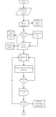 Figure 9(a): Flowchart of the controller – First stage
As the temperature reference is updated in the continued flowchart shown in Figure 9(b), the processor compares the temperature Tout, of hot extracted air from the collector to the new reference T2. If Tout is greater than T2, the electric heater is turned OFF so that the oven is solely powered by the collector; else the combined power sources continues as the SMC subroutine is called. The regulation of the electric heater, extraction and circulating fans by SMC generated signal begins to drive the oven temperature to the new reference point. Once again timer is set with the value of t2 and after the second stage soak time elapses “Paint Cured” is displayed on the LCD screen. The electric heater turned OFF and the oven shuts down.
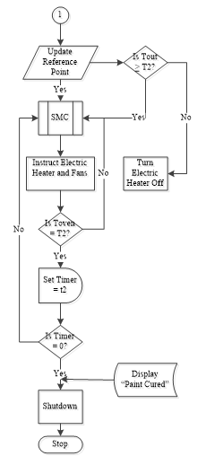 Figure 9(b): Flowchart of the controller – Second stage
Sliding mode control is a fast responds simple control method that switches between two discontinuous states in order to drive an output to track a reference input. Figure 10 is the flowchart algorithm of sliding mode control solar thermal/electricity powered oven. The control execution starts by reading three temperature variables; the reference temperature Td, this changes for a multiple reference inputs (T1 or T2 as in the main flowchart). Td is the desired temperature at any stage (T1 or T2). The second variable is Ta, which is the temperature of the surroundings and the third variable is the actual temperature in the oven, Toven.
Toven is continually acquired to track Td. As the variables are updated the equivalent control , and the switching control , are computed. The equivalent control is the control mechanism that maintains Toven to be steady once it reaches the sliding surface ( ). It is computed by taking the quotient of the total temperature rise in the oven chamber ( ) and the total heat capacity of the oven , (where and ).
The switching control is the mechanism that drives the actual output Toven, to the reference point Td in order to reach the sliding surface. The operation is achieved by changing the state of the Toven to be opposite in direction to any deviation from the sliding surface. That is taking the product of signum function of the error signal ( ), the heat capacity of the oven system and a positive constant M, so chosen as to be greater than the maximum limit of the system disturbances.
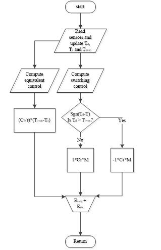 Figure 10: Sliding mode control flowchart
Table 2: Experimental test results
| Quantity | Value |
| Rise Time | 150.2369 (s) |
| Settling time | 165.7523(s) |
| Settling Max. | 60.8341 (°C) |
| Overshoot | 1.7970 (%) |
| Undershoot | 0 (%) |
| Peak | 61.1800 (°C) |
| Peak Time | 213.1673 (s) |
| Air Channel Temperature Max. | 50.10 (˚C) |
| Hydraulic Space Temperature Max. | 69.7 (˚C) |
| Collector Total Energy Supply
|
419,250.7 (W) |
Signum function outputs when the error signal is positive and when the error signal is negative. The control signals from the equivalent control and the switching control are summed up in a Flowchart merger to get the control law of the sliding mode control. The control law generates the signal which is returned to the micro-controller and the process repeats until the paint is cured.
3.4. Experimental Test Results and Analysis
The system setup is for combined solar and electricity as sources of heat energy. The experiments are performed for single temperature reference and double temperature references. A plot obtained from the single temperature level test is shown in Figure 11. The plot shows the temperature evolution in thick blue line which is how the sliding mode controller drives the oven temperature to the reference temperature shown in black line.
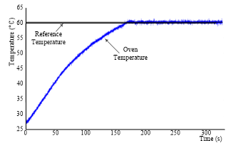 Figure 11: Oven temperature-time plot for a single reference point
Just as in the simulation results, the system has a rapid rise time in the experimental results; which demonstrates that the controller is an improvement over other convectional control methods. The controller also proves to be effective in tracking the reference temperature of 60°C with little or no deviation.
Table 2 is the statistical data collected from the analysis of oven temperature evolution logged in external drive while performing the experiment.
The table shows a rise time of 150.2369 s and settling time of 165.7523 s. It also shows settling maximum of about 60.8°C and an overshoot of about 1.8% with 0% undershoot. The maximum temperature recorded in the oven is 61.18°C which is the peak that occurred at 213.17 s.
The maximum temperature in the air channel that connects the solar collector to the oven is 50.10°C and the maximum temperature in the hydraulic space (gap between absorber plate and glass cover) of the collector is 69.7°C. The total energy supplied by the collector is 419,250.7 W.
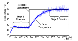 Figure 12: Oven temperature for double reference points
The second experimental demonstration test results are shown in the plot of Figure 12. The two reference points are 50°C and 120°C with each set to soak time of five minutes (300 s). The figure again shows that the controller effectively tracks multiple references at the various set time without much overshoot. However, noisy spikes begin to appear as the oven is in continuous use which become more pronounced as the temperature elevates. This is a design issue as a result of using thermistor with 150°C limit of maximum accurate range.
3.5. Payback Period and Energy Savings
Payback period is an estimate of the amount of time that is needed for cash inflow realized from a project to offset the initial cash outflow; it ignore the cost of maintenance [14-18] [19, 20, 21]. Powering of paint curing oven system with flat-plate air solar thermal collector to come with addition cost and the time required for the collector to generate energy that worth the cost.
In Table 2, the total energy the supplied to the oven by the collector is 419,259.7 W, for a period of 325 s. This is equivalent to1,290 W/s
This implies that in one hour the collector can supply
![]() Equation (27) shows that the collector generates 4.644 MJ of energy per hour. A kilowatt-hour of energy is 3.6 MJ and costs ₦47.8 in Nigeria that is equivalent of $0.13 (or thirteen cent).
Equation (27) shows that the collector generates 4.644 MJ of energy per hour. A kilowatt-hour of energy is 3.6 MJ and costs ₦47.8 in Nigeria that is equivalent of $0.13 (or thirteen cent).
![]() Equation (28) shows that the collector saves ₦61.66/hr
Equation (28) shows that the collector saves ₦61.66/hr
Assuming seven hours (7 hrs) of insolation per day over a period of one year (365 days) the equivalent cost of energy savings is ₦157,546.41 as shown in (29).
![]() The cost of solar thermal collector in Figure 8(a) and its operation auxiliaries is ₦210,009.36; the payback period is thus:
The cost of solar thermal collector in Figure 8(a) and its operation auxiliaries is ₦210,009.36; the payback period is thus:
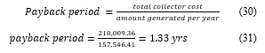 The payback period is about sixteen months.
4. Conclusion
This paper is an extension of work originally presented in 2019 IEEE International Conference on Sustainable Energy Technologies and Systems (ICSETS) [1]. It extends the control methodology approach and shows how the stability verification on the system model is done.
The work uses sliding mode control techniques and integration of solar thermal collector to solve oven temperature control and power optimization problem. Comparison of a model of an oven system designed and simulated in MATLAB/SIMULINK shows that sliding mode control method is an improvement over other control methods like PID control.
A convective paint curing oven has been built to verify the control method on paint curing process; Flat-plate air solar collector has also been built and incorporated into the oven system to reduce cost on utility bill. The developed control method was implemented for multi-stage temperature level using micro-controller and thyristor modules that switches electricity if the solar thermal collector is not supplying up to required temperature.
The system was setup and tested for verification and the experimental results show behavior similar to the simulation results. The results also show that the collector energy generation can payback the running and installation cost within sixteen months on an average insolation of 200W/m2 in Nsukka. The collector provides 43.27% of the energy requirement by the oven when the oven operates at 120˚C, which is considerably good.
Acknowledgment
This work is sponsored by Mirai Denchi Nigeria Limited.
- O. V. Ajah and E. C. Ejiogu, “Solar Therma/Electricity Paint curing Oven,” in IEEE International Conference on Sustainable Energy Technologies and Systems (ICSETS), Bhubaneswar, India, Mar. 2019.
- R. Talbert, “Curing,” in Paint Technology Handbook, Boca Raton, USA, Press Taylor & Francis, 2008, pp. 161-167.
- Despatch, “Industrial Oven Selection Guide,” in Thermal Processing Technology, 8860 207th Street West Minneapolis, MN 55044 USA, Despatch, 2016.
- N. Hambali, A. A. Rahim and A. A. Ishak, “Various PID Controller Tuning for Air Temperature Oven System,” in IEEE International Conference Proc. on Smart Instrumentation, Measurement and Applications (ICSIMA) , Kuala Lumpur, 2014.
- Y. Z. X. Gao and W. Guo, “Simulation and Research of Fuzzy Immune Adaptive PID Control in Coke Oven Temperature Control System,” in IEEE Proceedings of the 6th World Congress on Intelligent Control and Automation, Dalian, China, 2006.
- K. Ohishi, “Robust Temperature Control of Thermostatic Oven Based on Adaptive and Fuzzy Algorithm,” in IEEE Industrial Electronics Society IECON 15th Annual Conference, 1989.
- Z. Xuelei, W. Songling, C. Haiping and Z. Lanxin, “System Design and Economic Evaluation of Coke Oven Gas Utilization Projects,” in IEEE Conference, 2010.
- F. Pask, P. Lake, A. Yang and e. al., “Pask, F., Industrial oven improvement for energy reduction and enhanced process performance,” in Clean Techn Environ Policy, 2017.
- J. Kent, “http://www.pcimag.com,” Apr., 2008. [Online]. Available: https://www.pcimag.com/articles/95662-a-uniform-cure. [Accessed 10 Feb., 2017].
- E. C. Ejiogu, “High Performance Vector Control of the Induction Motor by Application of the Variable Structure System Theory,” PhD Thesis, Shinshu University, Nagano-City, Japan, 1994.
- V. I. Utkin, “Sliding Mode Control Design Principles and Applications to Electric Drives,” IEEE Trans. Industrial Electronics, vol. 40, no. 1, p. 23 – 36, Feb, 1993.
- K. D. Young, V. I. Utkin and Ü. Özgüner, “A Control Engineer’s Guide to Sliding Mode Control,” IEEE Trans. Control Systems Technology,, vol. 7, no. 3, pp. 328-342, 1999.
- B. Mohamed, M. Benyounes and Z. Souhila, “Comparison of Sliding Mode Control and Fuzzy Logic Applied to Wind Turbine Emulator,” in IEEE Conference 3rd International Symposium on Environmental Friendly Energie and Applications (EFEA), 2014.
- M. Jzernik and K. Dal, “Experimental Comparison of Discrete Time Sliding Mode and Conventional, PI Current Controller for IM Drives,” in IEEE 12th International Power Electronics and Motion Control Conference, 2006.
- K. Eriksson, D. Estep and C. Johnson, Applied Mathematics: Body and Soul Volume 1: Derivatives and Geometry in IR3, Singapore: Springer, 2004.
- V. Ajah and G. A. a. E. Ejiogu, “Sliding Mode Temperature Control for Hybrid Solar/Electricity Oven,” International Journal of Mechatronics. Electrical and Computer Technology (IJMEC), vol. 10, no. 37, pp. 4654 – 4664, July, 2020.
- A. Victor, “Sliding Mode Temperature Control: Hybrid Solar Thermal/Electricity Paint Curing Oven,” M.Eng Thesis, Electrical Engineering University of Nigeria, Nsukka, 2018.
- N. Derbel, G. Jawhar and Z. Quanmin, Applications of Sliding Mode Control, Singapore: Springer, 2017.
- S. Stelling, T. Y. R. Syah, R. Indrawati and D. Dewanto, “Role of Payback Period, ROI, and NPV for Investment in Clinical Health Business,” International Advanced Research Journal in Science, Engineering and Technology (IARJSET), vol. 5, no. 7, pp. 78 – 82, July, 2018.
- A. F. AWOMEWE and O. Oludele Olawale, “THE IMPORTANCE OF THE PAYBACK METHOD IN,” Blekinge Institute of Technology, Blekinge, 2018.
- M. K. Al-Ani, “A Strategic Framework to Use Payback Period in Evaluating the Capital Budgeting in Energy and Oil and Gas Sectors in Oman,” International Journal of Economics and Financial Issues (IJEFI), vol. 5, no. 2, pp. 469 – 475, 2015.