Model of Automatic Parking House

Adv. Sci. Technol. Eng. Syst. J. 5(2), 111–115 (2020);
 DOI: 10.25046/aj050214
This article deals with the issue of parking houses, storage mechanisms and how to control them. A laboratory model of a multi-storey underground automatic parking house was designed and created for this purpose, which is used to test a new innovative way of storing cars and specialized approaches to driving actuators. The model is based on an aluminum profile frame to which a newly made linear two-stage dual-sided telescopic mechanism and a two-axis positioning mechanism is attached. The emphasis is placed on the smooth movement of all axes which limits shocks caused by mechanism speed change while moving to a defined position.
1. Introduction
This paper is an extension of work originally presented in International Carpathian Control Conference 2019 [1] which deals with the design of whole automated parking house and new solution of car storing.
Automatic parking systems offer modern, sophisticated and intelligent car parking solutions in places where there is a lack of parking space for many vehicles. In such places as city centers, airports, hotels, housing estates, etc. it is possible to use parking houses, which will increase the parking area by the number of floors, whether in the above-ground or underground variant. This solution can be further improved by using an automated system with many advantages over the classic solution.
To demonstrate the functioning of a possible solution of such an automatic parking system, a model of an automatic parking house of the underground structure was created on the principle of a two-axis motion device with a dual-sided sliding telescopic storage mechanism. This solution brings a new perspective on the design of the storage mechanism and develops the widely used principles of automatic car parking, e.g. in [2-4].
The control of this model is provided by a distributed control system consisting of Arduino units in two levels. Arduino Nano microcontroller boards form the zero-order level together with the power modules for control of step and dc motors and represent the analogy of real intelligent systems such as intelligent frequency inverters. The Arduino Mega forms the top level, which represents the master control board of the model. Both levels communicate with each other via UART. The higher level is also ready for connection to the visualization software.
2. Description of Construction
For the purposes of this project, a model of a parking house was designed as physical support for the following solution of the control system and its software. In terms of the optimal ratio between price, size and assembly, the dimensions were chosen so that the device was able to work with 1:24 scale car models.
Some components, particularly the propulsion system, do not entirely match the overall proportions of the parking house model, but they have been used for the fact that they are standard, standardized components whose price is many times lower than the price of atypical prototypes made bespoke.
2.1. Design of the storage mechanism
The basic element of each automated parking house is the mechanism that transports cars from the entry area to the individual storage positions. The most commonly used principle is the transfer of a car on a pallet that the individual carriage systems of the garage convey between themselves. However, in this work, the principle used for transferring the car from the static to the moving part of the system is based on mutually passing support bars (see Figure 1), which support the wheels of the car and during their mutual pass the wheel is transferred from the bars with larger pitch to ones with smaller pitch and vice versa. Based on this principle, a storage mechanism has been developed that functions as a telescopic sliding dual-sided system with a support element mounted on the second stage of the telescopic device. In this way, the mechanism is able to eject the support element by more than one length of the retracted state, thus enabling the vehicle to be moved to the storage position without the support element being physically disconnected from the storage mechanism.
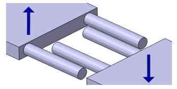 Figure 1: Mutually passing support bars
The storage mechanism (see Figure 2) consists of three basic parts, designed for a linear extension, symmetrically on both sides. The parts were made according to their design from ABS plastic by the 3D printing method based on the requirements for the range of motion, stiffness, and specific dimensions. To measure the deflection of the telescopic structure, a simple strength analysis with a load of 0.5 kg was performed, resulting in maximum stress (according to the HMH hypothesis) of 1.731 MPa and the maximum deflection of the first stage endpoint of 0.66 mm at the maximum assumed load. It has to be emphasized that during the analysis the assembly was considered as a solid body and the properties of 3D printed plastic undoubtedly differed from other manufacturing technologies.
The first telescopic stage drive is realized by a Microcon stepper motor of type SX17-1005LQCEF. This motor has a standardized NEMA 17 flange size, static torque of 0.52 Nm at a rated current of 1 A. The motor movement is transmitted over the pulley by a toothed belt of GT2 type mounted on the opposite end of the first stage slider from the underside.
For the second stage drive, the RC nano-servomechanism was used. It was modified so that the feedback was removed, and the motor is used as a conventional high-speed DC motor with a high ratio gear train due to its small mounting dimensions. The motor is mounted on a second stage moving part and its rotary motion is converted to linear by a pinion and a toothed rack running through the middle of the second stage.
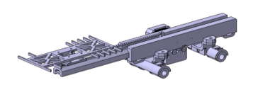 Figure 2: The storage mechanism
2.2. Design of the two-axis motion system
The main system enabling the storage mechanism to move in the handling space is a two-axis system (see Figure 3), capable of moving the car in the vertical axis between the floors and horizontally between the storage boxes within the floor. For this model, the mechanism was designed combining two basic principles: the industrial storage crane and the 3D printer’s motion system. Microcon SX17-1005LQCEF and SX17-1003LQCEF stepper motors were chosen to drive both axes. Due to many atypical parts, the method of 3D print was selected to create them. A toothed belt of GT2 type was selected for the transmission of the movement on a horizontal axis. On the vertical axis, due to the requirement for safe stopping of motion in the event of power failure, the trapezoidal screw was used – even at the cost of slower motion.
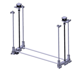 Figure 3: The motion system
2.3. Design of a frame
As a main load-bearing structure of the entire parking house, a design of a frame made of aluminum modular profiles with dimensions 30 x 30 mm was created (see Figure 4). This solution has been chosen especially with regard to the easy attachment of all parts into the profile grooves.
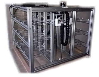 Figure 4: The parking house model frame
3. Realization of the Model
The construction of the parking house model for automatic parking of cars was realized on the basis of a previous design.
3.1. Motion system
The axes are formed by hardened; polished guide rods attached to the base frame. Linear ball bearings embedded in 3D printed carrier parts allow easy motion along the guide rods. Torque transmission of the motors is realized via a flexible coupling, a trapezoidal motion screw and a trapezoidal nut on the horizontal axis and over the pulley and a toothed belt as a drive of the storage mechanism.
The trapezoidal screw of the specific parameters meets the self-locking condition, so even in the event of a power outage or other failure, it will ensure a safe stop of the vertical movement of the mechanism. For verification, the conditions of self-locking in equations (1) and (2) are used.
 where ψ is the pitch angle (here from the manufacturer 4°07´), φ’ reduced friction angle of the thread, fz for steel – steel 0.15 and the angle of the thread profile α for a trapezoidal thread is 30°.
3.2. Storage mechanism
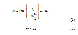
The most important and the most complex part of the whole model – the storage system (see Figure 5) was made using the 3D printing method as an assembly consisting of three main carrying parts and many other supporting elements.
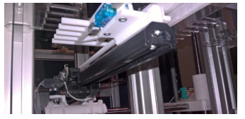 Figure 5: Extruded telescopic mechanism
The main carrier, printed on a 3D printer, has an inner groove for the middle carrying part – the first stage of the telescopic mechanism. Also, there are two smooth pulleys mounted on the underside, through which the toothed belt passes to drive the first telescopic stage. Through the holes on the side of the main carrier, it is possible to mount the stepper motor to drive the first stage.
The second carrier – the first telescopic stage – has such a profile that passes as tightly as possible through the groove in the base part. Also, it has another shaped groove for guiding the moving carriage – the second telescopic stage.
A toothed pinion, made by 3D print, is attached to the output shaft of the second stage motor, transferring motion to the toothed rack, which is solidly connected to the first stage of the telescopic mechanism and passes through the middle of the second stage.
3.3. Static parking spaces
Static parking spaces were made of plexiglass parts cut by a laser (see Figure 6). Ladder shelves have been created, which always in pairs form a parking space for one car. One of their ends was heat-bent at a right angle so that it could be then attached to the main frame of the model.
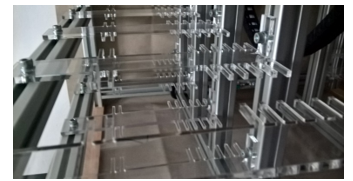 Figure 6: Parking spaces
3.4. Sensors
Several types of sensors were used to build the model. The main purpose of these sensors is to define end positions, homing positions, pullout position control and parking space occupancy detection.
For these purposes, sensors of the following types were used:
- Mechanical end stops (homing, handling space definition)
- Hall sensors (determining the position of the second stage of the telescopic mechanism)
- Optical IR gates (homing of the first stage of the telescopic mechanism, incremental sensors)
- Reflective IR sensors (parking space occupancy detection)
For easier processing of signals from occupancy detection sensors, the PCB was used, with sensitivity tuning and conversion to serial signal using a shift register of “parallel in – serial out“ type (see Figure 7).
 Figure 7: Signal conversion boards
All cabling has been run in power chains in places of motion to prevent cables from entering the moving parts of the system.
4. Model Control
A multilevel system (see Figure 8) has been designed to control the model, consisting of a master controller, build on the Arduino Mega 2560 microcontroller board, which provides data acquisition, communication with the user and with superior control level, and mainly management of three subsystems controlling the movement of each axis of the model. These subsystems are built on the Arduino Nano microcontroller boards, which in combination with the Pololu DRV8825 power stepper motor driver and with the L298N H-bridge for driving DC motor, is an analog of a real intelligent control system, such as an intelligent frequency converter.
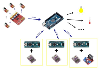 Figure 8: Control system diagram
The UART hardware communication device was used for serial communication between the mainboard and the subsystems.
The DC motor is controlled by a bridge driver by switching the respective inputs which control the power components of the driver and the speed of motion is given by the input PWM modulated enable signal.
4.1. Stepper motor control
A separate chapter in the control algorithm is controlling stepper motors using the Pololu DRV8825 stepper motor driver. This driver switches the individual phases of the motor, eventually provides micro-stepping, depending on the DIR and STEP input signals, where one determines the direction of motion and the other responds to the starting edge of the pulse by performing one step of the motor.
Control pulses for the driver are generated by the microcontroller of the respective axis using the timer interrupt handler. This, depending on the desired time gap between pulses, generates an interrupt flag, triggering the service subroutine, switching the respective outputs and calculates the requested pause time. The longer the pause is, the slower the motor moves.
To ensure the smoothness of the engine’s acceleration and deceleration, and to prevent step loss due to a rapid transition from idle to maximum speed, an algorithm was developed to accelerate and decelerate the engine according to the ramp function. Some of these principles can be also found in the online articles (D. Austin, Generate stepper-motor speed profiles in real time, Atmel, Linear speed control of stepper motor) or in [5].
The time between control pulses can be calculated using the following formula (3)
![]() where c0 is the initial pulse pause length, cn is the length of nth pulse pause and n is the calculation step. This way the ramp function is calculated until the motor speed reaches the maximum value.
where c0 is the initial pulse pause length, cn is the length of nth pulse pause and n is the calculation step. This way the ramp function is calculated until the motor speed reaches the maximum value.
Since the calculation of the two square roots is very demanding for the microcontroller processor and does not meet the requirement for the shortest possible interrupt service subroutine time. It is useful to replace the previous formula with Taylor series (4) with a certain, not so significant inaccuracy, and calculate the pause between steps from the previous value according to
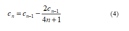 This measure reduces the calculation to only division of two numbers that is considerably faster than the square root calculation. In order to further accelerate the calculation, measures have been introduced replacing the more demanding division of decimal numbers by dividing integers into two phases. Firstly, the integer is divided normally and then the modulo division is used to obtain the remainder of the division, which in the next step is added to the divider to reduce the inaccuracy of the calculation [6].
4.2. Homing
Movement of motional parts to the default, home position called “homing” is accomplished by a series of algorithms, each controlled by the respective combination of the microcontroller and the power driver.
The horizontal and vertical axes travel to its home limit switch at a reduced speed, and after activation, it will leave enough to switch off the switch again. The algorithm also considers the situation when it is necessary to get into the home position after a non-standard situation, when one of the limit switches is active at the beginning of the process, especially when the home switch is active. In this case, the switch will firstly move from the switch and then the homing will start.
The first stage of the storage mechanism performs homing by means of two optical gates located at the end of the base part of the mechanism. If the two gates are not interrupted, the slider moves in small increments in the direction of the uninterrupted sensor. At the moment of its deactivation, a predefined deviation from the default value is corrected.
The second stage firstly “moves back” to the nearest Hall sensor in the given direction and then moves forward to its home sensor. If the stage moves back even to the outer sensor, it is assumed that the starting position is already verified with enough space behind it.
5. Conclusion
During a realization of this project, a model of an underground parking house for parking cars, driven by stepper and DC motors, and designed with suitable position sensors, end position sensors, and sensors of occupied parking space, was designed and built. Many 3D prints have been used to produce many atypical parts. The individual parking positions are made of plexiglass ladder shelves. Vehicle storage is performed by a dual-sided sliding telescopic storage mechanism specially designed for this model, operating on the principle of passing support bars.
Next, a multi-level control system based on Arduino microcontroller boards was designed so that one of them serves as a master controller of the model and others formed intelligent drivers for the individual motion axes of the model. All of these individual boards have been programmed and interconnected by the UART communication device.
This project brings a new perspective on car manipulation and storing and allows further development of algorithms for optimal automatic parking.
Conflict of Interest
The authors declare no conflict of interest.
Acknowledgment
This work was supported by the European Regional Development Fund in the Research Centre of Advanced Mechatronic Systems project, CZ.02.1.01/0.0/0.0/16_019/0000867 within the Operational Programme Research, Development and Education and the project SP2020/57 Research and Development of Advanced Methods in the Area of Machines and Process Control supported by the Ministry of Education, Youth and Sports.
- R. Guráš, M. Mahdal, “Parking house action subsystem control,“ in Proceedings of 2019 20th International Carpathian Control Conference (ICCC), Krakow-Wieliczka, Poland, 2019, doi: 10.1109/CarpathianCC.2019.8765989
- U. Maheswari, D. Aswini, G. Murtugudde, B. Karthiga, “Automatic car parking system“ Int. J. Pure Appl. Math. (Online), Vol. 120, No. 6, 2018. ISSN: 1314-3395
- I. L. J. Hamelink, The Mechanical Parking Guide, CreateSpace Independent Publishing Platform, 2011, ISBN 1-466-43786-3
- A. Mathijssen, A. J. Pretorius, “Verified Design of an Automated Parking Garage“ in Formal Methods: Applications and Technology: 11th International Workshop, FMICS 2006 and 5th International Workshop PDMC 2006, Bonn, Germany, 2006, doi: 10.1007/978-3-540-70952-7_11
- P. Novák, Mobilní roboty: pohony, senzory, řízení, Praha: BEN – technická literatura, 2005, ISBN 80-7300-141-1
- J. Czebe, J. Škuta, “Usage of single-chip computers for control MIMO systems,“ in Proceedings of 2017 18th International Carpathian Control Conference (ICCC), Sinaia, Romania, 2017, doi: 10.1109/CarpathianCC.2017.7970428
No related articles were found.