In Body Antenna for Monitoring and Controlling Pacemaker

Adv. Sci. Technol. Eng. Syst. J. 5(2), 74–79 (2020);
 DOI: 10.25046/aj050209
This paper is an extension of work originally presented in 2019 International Conference on Automation, Computational and Technology Management (ICACTM). A micro-strip patch in-body designed antenna is constructed on pacemaker to monitor and control the pacemaker wirelessly. The antenna is intended for ISM (Industrial, Scientific, and Medical) band (2.4 GHz to 2.48 GHz). A perfect electric conductor (PEC) is considered as pacemaker body and used as the ground of the propounded antenna having dimensions 40 x 30 x 10 mm3. The patch material is chosen Copper having dimensions 35 x 22 x 0.1 mm3 and covered up with substrate material Rogers R03010 (loss tangent δ = 0.0035 and dielectric constant, er = 10.2) with thickness of 1.55 mm to make it compatible in human body. The designed antenna is placed and analyzed in 2/3 muscle equivalent phantom by changing the depth of the antenna. Results disclose that operating frequency is 2.464 GHz with reflection coefficient -28.37 dB. The antenna maintains frequency range from 1.8075 GHz to 3.445 GHz, which represents wide bandwidth of 1.6375 GHz. To ensure the human body safety, specific absorption rate is analyzed and found 0.937 W/Kg for 10g tissue at operating frequency, which makes it biocompatible. The surface current distribution, Voltage Standing Wave Ratio, Current density, far-field radiation characteristics, radiation efficiency, and total efficiency are investigated to analyze the effect and performance of the designed antenna. CST Microwave Studio is used for simulation and analysis the parameters of the antenna.
1. Introduction
Nowadays in our modern scenario, heart attack is very familiar disease caused by loss of blood supply. It appears when the heart is beating too rapidly or when the body is not receiving enough blood [1]. A small electrical medical device called artificial implantable pacemaker provides an electrical pulse to the heart with proper intensity by the electrodes [2]. The main objective of pacemaker is to regulate irregular heartbeats (known as arrhythmias) at normal rate. Many organizations come up with distinctive features, such as wireless communication and monitoring assistance [3]. This monitoring and controlling system is extremely relevant because it decreases the amount of eye to eye visits with doctors, as well as the physical and mental stress of patients. Since it can communicate wirelessly, there is no need to cut the skin, which can prevent infection from a germ in a medical diagnosis, but the antenna is needed to transmit the data wirelessly.
A micro-strip patch antenna’s geometric shape contains a shedding layer on first part of the dielectric substrate with a ground plane on the next. Radiating element can be square, circular, semicircular, triangular etc. [4]. In present days, a number of antenna design have been proposed on several researches for the different applications. With many advantages, this antenna can communicate with others wireless system spontaneously [5, 6]. Easy to manufacture, lightweight, low profile, low cost, replaceable and high efficiency is such advances. The popularity of patch antenna in microwave communication is raised nowadays that requires semispherical coverage. Safety of a patient with a compact size, as well as wider bandwidth and radiation efficiency is the main concern to design an antenna [7, 8]. Various types of antenna have been developed, e.g. meander line, monopole, and loop antenna for wireless monitoring [9, 10].
ISM or Industrial, Scientific and Medical band (2.4 GHz – 2.4835 GHz) and MICS or Medical Implant Communication System band (402 MHz to 405 MHz) specified for bio-suitable antenna by U.S. Federal Communications Commission and European Radio communications Committee (ERC) in wireless medical telemetry service (WMITS) [11]. ISM band has shorter wavelength due to its high frequency area range apart from MICS band has wider wavelength due to its smaller frequency. Therefore, ISM band is extra reasonable than MICS to design an antenna on pacemaker [12].
In this article, a design of bio-implantable micro-strip patch antenna is propounded for monitoring and controlling pacemaker, which operates at ISM band. The pacemaker with the antenna placed inside 2/3 muscle equivalent phantom, then the characteristics are analyzed. The performance is also analyzed by changing depth of the pacemaker in 2/3 muscle equivalent phantom. The pacemaker box considered as box of PEC (perfect electric conductor) as well as ground of the proposed antenna [13]. Rogers R03010 (er = 10.2) covers the antenna from all the side can also called superstrate and substrate of the antenna for its flexibility and durability characteristics [14]. All the characteristics of the propounded antenna observed in CST microwave studio and discussed in this article.
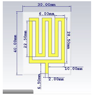 Figure 1: Propounded micro-strip patch antenna front view with dimension.
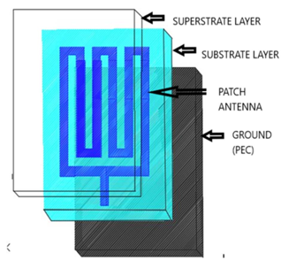 Figure 2: Antenna Structure
2. Structure and Design Method
2.1. Design of Antenna
The propound micro-strip patch antenna has the length 35 mm and width 22 mm respectively, which overcome the most challenging issues – biocompatibility and size. The designed antenna is consisting superstrate, patch, substrate, and ground. Copper is chosen for patch with 0.1 mm of thickness. The pacemaker box is built with PEC or perfect electric conductor with thickness of 0.1 mm from all sides and it acts as ground of the antenna. The substrate and superstrate are made with Rogers R03010 that covers full patch material with 1.55 mm thickness.
The geometrical front view of antenna shows all the dimensions of patch, which are placed in Figure 1. The patch is located in the middle of the superstrate and substrate with 35 x 22 x 0.1 mm3 to reduce the effects of a high conductive human tissue as well as to avoid shortening the antenna [12-15]. Having 6.5 mm length and 2 mm width, feed line is also shown. All the dimensions are organized in Table 1.
Table 1: The Antenna Parameters
| Antenna Part | Material | Parameter | Value (mm) |
| Superstrate | Rogers | Length | 40 |
| Width | 30 | ||
| Thickness | 1.55 | ||
| Patch | Copper | Length | 35 |
| Width | 22 | ||
| Thickness | 0.1 | ||
| Substrate | Rogers | Length | 40 |
| Width | 30 | ||
| Thickness | 1.55 | ||
| Ground | PEC | Length | 40 |
| Width | 30 | ||
| Thickness | 0.1 |
2.2. Design of Pacemaker Casing
Figure 3 shows casing of Pacemaker and the location of the antenna with waveguide port. The antenna patch covers with substrate and superstrate is placed on the top surface of the antenna. The waveguide port is connected underneath the feed line from where the power of input is given. The red part states the port of the waveguide as shown in Figure 3. Dimensions of the pacemaker case are tabulated in Table 2.
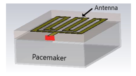 Figure 3: Antenna with Pacemaker Case Showing Waveguide Port
Table 2: Pacemaker Case Dimension
| Name of Parameters | Value (mm) |
| Pacemaker Length | 30 |
| Pacemaker Width | 40 |
| Pacemaker Thickness | 10 |
| Pacemaker Case Thickness | 0.1 |
2.3. Structure of Body Phantom
As shown in Figure 4, the pacemaker with surfaced antenna is placed inside the 2/3 muscle-equivalent phantom. The interval between antenna and the phantom’s surface is denoted with “d” and it varies depending on gender and age.
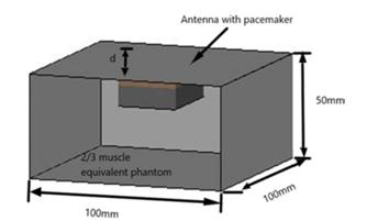 Figure 4: 2/3 muscle-equivalent phantom model pacemaker inside
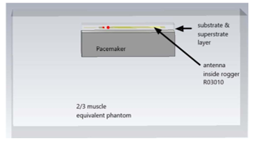 Figure 5: Cross sectional view of 2/3 muscle phantom with pacemaker inside.
Cross sectional view of the designed antenna with pacemaker inside the 2/3 muscle equivalent phantom is shown in Figure 5. The positioning pattern of pacemaker is clearly described.
3. Characteristics Analysis of Designed Antenna
3.1. Reflection coefficient or S11 parameter
Reflection coefficient or S11 parameter measures the quantity of power that radiated or reflected from an antenna [16]. The return loss is noticed after implanting the proposed antenna inside 2/3 muscle equivalent phantom model at resonant frequency. In Figure 6, the X-axis is in GHz range, which represents the frequency and the Y-axis is in dB scale, which constitutes the return loss. The resonant frequency or operating frequency of the propounded antenna is found 2.464 GHz, which is in ISM band and that turns the antenna into biocompatible and also return loss of -28.369 dB that indicates better performance by maximum radiation of the antenna [14]. The bandwidth of the propounded antenna is observed 1.6375 GHz (1.8075 GHz to 3.445 GHz) by sketching a linear line in -10 dB, which is enough sufficient to implant on human body [14].
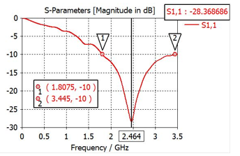 Figure 6: Return loss (S11 parameter) of the antenna inside 2/3 muscle equivalent phantom model.
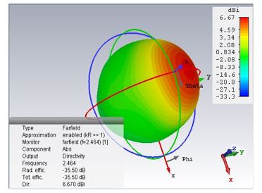 Figure 7: Far-field radiation pattern view (3D) of the propounded antenna inside 2/3 muscle equivalent phantom model.
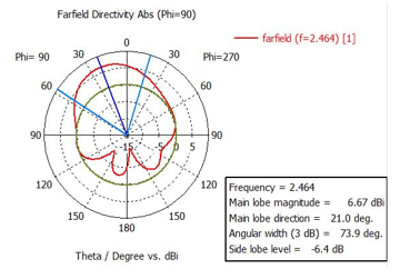 Figure 8: Polar view of far-field radiation pattern of the designed antenna.
3.2. Far-field radiation pattern
The radiation characteristics of the proposed antenna is explained in Figure 7. As the antenna is designed for monitoring and controlling pacemaker so unidirectional directivity is maintained to get the best values because pacemaker is a static device inside human body. Various parameters such as the directivity, total efficiency and the radiation efficiency is got 6.67 dBi, -35.5 dB and -35.5 dB respectively at the resonance frequency of 2.464 GHz and represented the radiation characteristics of the designed antenna. Figure 8 is displayed the far-field radiation pattern’s polar view of the proposed antenna with main lobe magnitude 6.67 dBi.
3.3. Voltage standing wave ratio or VSWR
The voltage standing wave ratio is a function of the coefficient of reflection and of the intensity reflected from antenna [16]. For better performance, VSWR should be in between 1 to 2. In Figure 9, the X-axis is in GHz range, which represents the frequency and the Y-axis is ratio, which represents VSWR. In addition, it founds 1.08 at resonance frequency 2.464 GHz.
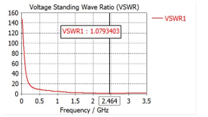 Figure 9: Voltage standing wave ratio (VSWR) of the antenna inside 2/3 muscle equivalent phantom model.
3.4. Specific Absorption Rate (SAR)
SAR is measured by the radiation of the surrounding tissue [17] that is used for safety purpose. According to FCC, in 10g tissue and 1mW input power, SAR must be less than 2 W/Kg to ensure higher safety [18, 19]. From Figure 10, Maximum Specific Absorption Rate (SAR) for the proposed antenna is noticed 0.937 W/kg at operating frequency for 10g tissue.
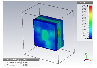 Figure 10: SAR distribution of the propounded antenna for 10g tissue in 1mW of input power.
3.5. Current density
Figure 11 shows the current density (abs) of the antenna at resonance 2.464 GHz. In addition, the current magnitude is not same in every position of the antenna patch. The current density in patch lies between 1017 A/m2 to 1176 A/m2. In addition, the maximum current density is found 5851 A/m2.
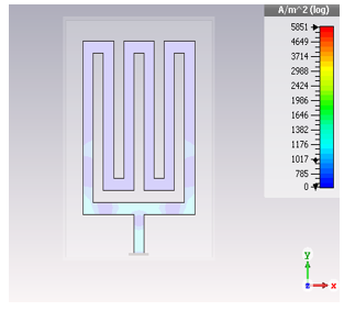 Figure 11: Current density of the designed antenna at 2.464 GHz.
3.6. Surface current distribution
The surface current distribution of the designed antenna at resonance frequency 2.464GHz is shown on Figure 12. The maximum current is found 52.5 A/m in design while the peck current on patch is found about 14.3 A/m. Figure 12 is also clearly described that the current is high on the lower edges which close to feeding point and low on the upper edges.
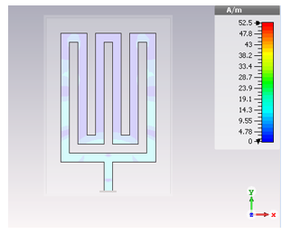 Figure 12: Surface current distribution of the designed antenna at 2.464 GHz.
4. Comparison Analysis
4.1. For various depth
Depending on the gender and age, the depth of the pacemaker is varied and analyzed. The depth defines the distance between the phantom surface and the superstrate surface. As shown in Figure 13, the reflection coefficient or S11 and the operating frequency is slightly shifted with the change of depth (d). Table 3 is shown the total changelog for different depth of pacemaker.
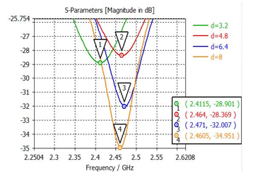 Figure 13: Return loss or S11 parameter of the antenna for various depth
Table 3: Changelog with different depth
| Position | Depth (mm) | Operating Frequency | S11 |
| 1 | 3.2 | 2.4115 | -28.901 |
| 2 | 4.8 | 2.464 | -28.369 |
| 3 | 6.4 | 2.471 | -32.007 |
| 4 | 8 | 2.4605 | -34.951 |
4.2. By changing material
The designed antenna parameters are also analyzed with two patch materials Copper, Gold and two substrate-superstrate materials Roger and FR-4 variations. As shown in Figure 14, the resonance is found 2.464 GHz frequency for all possible combinations and return loss or S11 parameters are almost same in the variations. Table 4 displays all the parameters findings by changing the materials.
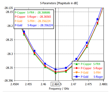 Figure 14: Return loss or S11 parameter of the antenna for different material.
Table 4: Changelog with different materials
| Patch | Substrate | S11 | Directivity | VSWR | SAR |
| Copper | FR-4 | -28.37 | 6.67 dBi | 1.07934 | 0.937 |
| Copper | Roger | -28.36 | 6.67 dBi | 1.07937 | 0.937 |
| Gold | FR-4 | -28.35 | 6.67 dBi | 1.07946 | 0.937 |
| Gold | Roger | -28.35 | 6.67 dBi | 1.07946 | 0.937 |
5. Conclusion
In this article, a micro-strip patch antenna is proposed for monitoring and controlling pacemaker. Biocompatibility have been checked by embedded the propounded antenna with pacemaker inside 2/3 muscle equivalent phantom. The depth is varied and analyzed to ensure same characteristics for any gender and any age’s people. S11 or reflection coefficient is found -28.37 and the resonance frequency is found 2.464 GHz for 4.8 mm depth. Pacemaker is one of the vital device nowadays for heart patients, especially for arrhythmias patients. Any kind of interruption in working of pacemaker can turn a patient into death. Therefore, monitoring and controlling pacemaker is become most important issue for pacemaker holders. In conclusion, according to the antenna performance, the propounded antenna is biocompatible and applicable for medical application with proper output.
- R. R. Hasan, M. A. Rahman, S. Sinha, M. N. Uddin, T. R. Niloy, “In Body Antenna for Monitoring Pacemaker” in 2019 International Conference on Automation, Computational and Technology Management (ICACTM), London, United Kingdom, 2019. doi: 10.1109/ICACTM.2019.8776836
- Y. Hao, Y. Li, D. Liao, L. Yang, “Seven times replacement of permanent cardiac pacemaker in 33 years to maintain adequate heart rate: a case report” Annals of translational medicine, 3(21), 2015. doi: 10.3978/j.issn.2305-5839.2015.11.35
- P. Soontornpipit, C. M. Furse, Y. C. Chung, “Miniaturized biocompatible microstrip antenna using genetic algorithm,” IEEE Transactions on Antennas and Propagation, 53(6), 1939-1945, 2005. doi: 10.1109/TAP.2005.848461
- H. Werfelli, K. Tayari, M. Chaoui, M. Lahiani, H. Ghariani, “Design of rectangular microstrip patch antenna” in 2016 2nd International Conference on Advanced Technologies for Signal and Image Processing (ATSIP), Monastir, 2016. doi: 10.1109/ATSIP.2016.7523197
- C. Liu, Y. Guo, H. Sun, S. Xiao, “Design and Safety Considerations of an Implantable Rectenna for Far-Field Wireless Power Transfer” IEEE Transactions on Antennas and Propagation, 62(11), 5798-5806, 2014. doi: 10.1109/TAP.2014.2352363
- S. Gollakota, H. Hassanieh, B. Ransford, D. Katabi, K. Fu, “They can hear your heartbeats: non-invasive security for implantable medical devices” Proc. ACM SIGCOMM 2011, 41(4), 2-13, 2011. doi: 10.1145/2018436.2018438
- W. El Hajj, C. Person, J. Wiart, “A Novel Investigation of a Broadband Integrated Inverted-F Antenna Design; Application for Wearable Antenna” IEEE Transactions on Antennas and Propagation, 62(7), 3843-3846, 2014. doi: 10.1109/TAP.2014.2318061
- Z. Duan, Y. Guo, M. Je, D. Kwong, “Design and in Vitro Test of a Differentially Fed Dual-Band Implantable Antenna Operating at MICS and ISM Bands” IEEE Transactions on Antennas and Propagation, 62(5), 2430-2439, 2014. doi: 10.1109/TAP.2014.2309130
- J. Kim and Y. Rahmat-Samii, “Implanted antennas inside a human body: simulations, designs, and characterizations” IEEE Transactions on Microwave Theory and Techniques, 52(8), 1934-1943, 2004. doi: 10.1109/TMTT.2004.832018
- P. Soontornpipit, C. M. Furse, Y. C. Chung, “Design of implantable microstrip antenna for communication with medical implants” IEEE Transactions on Microwave Theory and Techniques, 52(8), 1944-1951, 2004. doi: 10.1109/TMTT.2004.831976
- K. S. Nikita, Handbook of Biomedical Telemetry, IEEE press, 2014.
- H. Usui, M. Takahashi, K. Ito, “Radiation characteristics of an implanted cavity slot antenna into the human body” in 2006 IEEE Antennas and Propagation Society International Symposium, Albuquerque, NM, 2006. doi: 10.1109/APS.2006.1710726
- T. Houzen, M. Takahashi, K. Saito, K. Ito, “Implanted Planar Inverted F-Antenna for Cardiac Pacemaker System” in 2008 International Workshop on Antenna Technology: Small Antennas and Novel Metamaterials, Chiba, 2008. doi: 10.1109/IWAT.2008.4511351
- M. Islam, R.R. Hasan, M. Haque, S. Ahmad, K. Mazed, M. Islam, “In-Body Antenna for Wireless Capsule Endoscopy at MICS Band” in Computing Conference 2018, London, United Kingdom, 2018. doi: 10.1007/978-3-030-01177-2_59
- S. Sinha, R. R. Hasan, M. A. Rahman, M. T. Ali, M. N. Uddin, “Antenna Design for Biotelemetry System” in 2019 International Conference on Robotics, Electrical and Signal Processing Techniques (ICREST), Dhaka, Bangladesh, 2019. doi: 10.1109/ICREST.2019.8644307
- R. R. Hasan, M. A. H. Shanto, S. Howlader, S. Jahan, “A novel design and miniaturization of a scalp implantable circular patch antenna at ISM band for biomedical application” in 2017 Intelligent Systems Conference (IntelliSys), London, United Kingdom, 2017. doi: 10.1109/IntelliSys.2017.8324286
- N. A. Islam, F. Arifin, “Performance analysis of a miniaturized implantable PIFA antenna for WBAN at ISM band” in 2016 3rd International Conference on Electrical Engineering and Information Communication Technology (ICEEICT), Dhaka, 2016. doi: 10.1109/CEEICT.2016.7873145
- E. Safety, S. C. Committee, N. Radiation, I. S. Board, “IEEE Recommended Practice for Measurements and Computations of Radio Frequency Electromagnetic Fields With Respect to Human Exposure to Such Fields 100 kHz –300 GHz” Measurement, 2002, 2008.
- J. H. Bernhardt, “The New ICNIRP Guidelines: Criteria, Restrictions, and Dosimetric Needs” Radio Frequency Radiation Dosimetry and Its Relationship to the Biological Effects of Electromagnetic Fields. NATO Science Series (Series 3: High Technology), 82, 2000. doi: 10.1007/978-94-011-4191-8_56