
Fuzzy Logic Control Management with Stand Alone Photovoltaic – Fuel Cell System
Volume 5, Issue 1, Page No 424-430, 2020
Author’s Name: Ehab Mohamed Zakaria1,a), Shawky Hamed Arafa1, Maged Naguib Fahmy Nashed2, Salah Ghazi Ramadan1
View Affiliations
1Faculty of Engineering, Benha University, Egypt
2Electronics Research Institute, Cairo, Egypt
a)Author to whom correspondence should be addressed. E-mail: Eng_ehab_sakr@yahoo.com
Adv. Sci. Technol. Eng. Syst. J. 5(1), 424-430 (2020); ![]() DOI: 10.25046/aj050154
DOI: 10.25046/aj050154
Keywords: Hybrid system, Photovoltaic, Fuel cell, Electrolyzer, FLC

Export Citations
In this paper, a Hybrid System introduced (HS), which consists of Solar Photo-Voltaic (PV) system and the Fuel Cell (FC) System as alternative source of electrical power. The HS is used to supply the required electricity to a Single-Phase load with the help of Pulse Width Modulation Voltage Source Inverter (PWM-VSI). The PV provide the FC system with the required power to be used when it is needed to feed the loads during the absent of the solar sun lights. The FC system generate the Hydrogen (H2) from electrolyzer which Supplied with the Photo-Voltaic energy and water (H2O). While, the generated H2 is reserved in a Tank which provides the FC Stack by the required Hydrogen level. The output voltage from the FC Stack then, Boosted and converted to AC voltage suitable for the loads using a PWM-VSI. The fuzzy logic control (FLC) is designed to control management between level of tank H2 and power demand of load. The individual components are simulated in MATLAB/Simulink environment and tested, also, complete system modeling is presented, and the results obtained are found to be satisfactory.
Received: 23 December 2019, Accepted: 12 February 2020, Published Online: 25 February 2020
1. Introduction
A Standalone Hybrid System (HS) supplies the load by electricity without connection to the centralized power stations. Hybrid systems (HS) used in remote areas, where there are no electricity sources available therefore, selection of hybrid systems (HS) are Suitable for these areas. The paper purpose is to simulate and model the various components of a Photovoltaic Fuel-Cell (PVFC) hybrid system which is preferred to provide the demands of electric for areas far from the grid. Modeling and simulations for the presented system are performed using Simulink/ MATLAB package and results are presented to verify the effectiveness of this system.
The photo-voltaic energy (PV) is widely used in low power system applications among the renewable energy sources. PV generators have many advantages such as being pollution free, long life, silent, time etc. photo-voltaic (PV) have variable output power depending on the weather conditions variations [1, 2]. One way for overcoming this problem is to integrate and Combine the photo-voltaic array with other power sources for example, Fuel cell (FC). The selection of FC beak up power supply is a very attractive when it used with an intermittent source of power generation such as photo-voltaic power due to several attractive features of FC like fast load response and efficiency [3, 4]. PV installed considered as one of the alternative energy sources for clean generated energy. The power produced in a PV is in DC power form. Whereas certain cases may allow the direct using of the generated DC power from PV, while frequently required to convert the generated DC power to an AC power for control and integration into load system.
A Hybrid Systems consisting of PV-wind-diesel is used in [5, 6]. But due to increasing cost of diesel and use of the diesel environmental pollution is created that makes the operation of diesel engine prohibited. Another type of Hybrid Systems consisting of a wind-hydro is fed grid and inverter used to fed AC load where the power converters are used to improve the precision of the power system [7, 8].
FLC has been employed as a maximum power point tracking tool in [9]. The FLC was also used as a tool for power management in the standalone PV power system described in [10]. The work presented in [11] shows that the stand alone a hybrid power system and can be improved with FLC when it is used as management power for the best operation.
2. A Dynamic Model of Hybrid System
The equivalent circuit of the PV and the various equations leading to equation are provided in [1];
![]() As shown in Figure 1, the Simulink model of the module and PV generator is Consists of diode, photo current source, series and parallel resistor which describing the internal resistance to the current flow and expressing the leakage current. All data of system is written in our paper [11]. In Figure 2, the V-I characteristic curves of the simulated module at various irradiance levels and at various PV cell temperatures. It is seen that at constant PV cell temperature, increasing the irradiance will increase the short circuit current largely and increase the open circuit voltage slightly.
As shown in Figure 1, the Simulink model of the module and PV generator is Consists of diode, photo current source, series and parallel resistor which describing the internal resistance to the current flow and expressing the leakage current. All data of system is written in our paper [11]. In Figure 2, the V-I characteristic curves of the simulated module at various irradiance levels and at various PV cell temperatures. It is seen that at constant PV cell temperature, increasing the irradiance will increase the short circuit current largely and increase the open circuit voltage slightly.
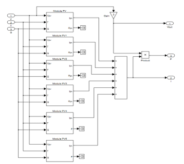 Figure 1. Simulink model of the module and PV generator
The parts of the system as Proton Exchange Membrane Fuel-Cell (PEMFC), Hydrogen Storage System data and equations are written in reference [11]. Figure 3, is shown the voltage-current density (V-I) characteristic of the FC module. While Figure 4, is shown a complete Simulink model for the Electrolyzer.
Since variable voltage needed so, the buck-boost converter is preferred. It is converting the supply voltage source to higher and lower voltages at the load terminals. The voltage of load terminals is controlled by continuously adjusting the duty ratio of the buck-boost converter power switch. Since the voltage polarity at the load terminal is opposite to the voltage polarity at the source terminal for most DC/DC converter types. In steady state condition, the inverting type buck-boost converter output voltage is given in Equation [2];
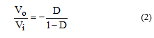
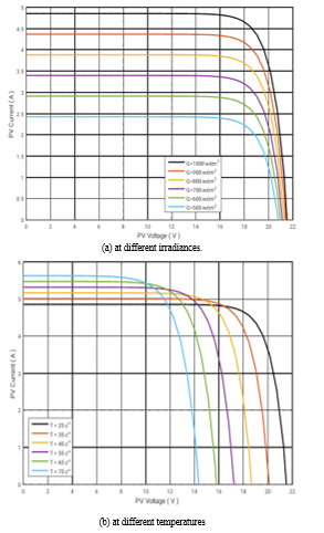 Figure 2. V–I characteristic curves of the PV module
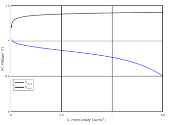 Figure 3. Characteristic curve of the FC module for the theoretical and actual voltage.
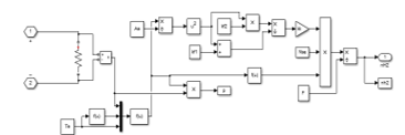 Figure 4. A brief model of electrolyzer model using Simulink
Thus, the output voltage can be regulated by controlling duty ratio of the used semi-conductor output voltage to higher or lower than the voltage of the source through properly control the MOSFET power switch operating duty ratio. The characteristic of the buck-boost depends on the value of the capacitor and inductor. The considered factors to determine the value of inductance include the input voltage range, the output voltage range, the inductor maximum current, and the switching frequency. The capacitor is used to regulate the voltage. The capacitance depends on the inductor current ripple, the switching frequency, and the desired output voltage ripple. Figure 5 is showing the Buck-Boost converter DC control model by MATLAB/Simulink.
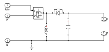 Figure 5. Buck/Boost DC Converter.
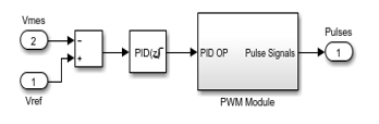 Figure 6. Pulse and Regulation Model
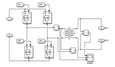 Figure 7. Single Phase PWM Inverter
The output voltage regulation of the Buck-Boost Converter is carried out using a PID controller as shown in Figure 6. Then, the controller output used as reference value for the PWM module to generate the required pulses with a suitable duty cycle.
Inverter modelling is a simple topology with a IGBT H-bridge inverter and a linear transformer which is simple to be implemented and completely isolated. The inverter converts the DC/AC with RMS value and Frequency suitable for the connected loads. Figure 7, indicate the MATLAB/Simulink model for the single phase PWM VSI with linear transformer.
3. Control System
3.1. MPPT Algorithm
Figure 8 a present perturb and observe algorithm, (P&O) while a simply changes a variable X, is a variable in current, voltage or duty cycle (D). to obtain the next X, ΔX stay as it during ΔT, then obtain power output of PV array.
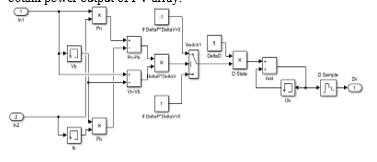 Figure 8. P&O MPPT Algorithm Modules
3.2. FLC Management
The order by FLC offer the advantage of being robust, efficient and works to the control management between the level of tank H2 and the power demand of the load FL is control of the ON/OFF inverter switch. There are different ways to implement a fuzzy regulator but in general the presentation adopted splits up in three steps: the fuzzification, inference and defuzzification as shown in figure 9. Figure 10, shows the implementation of our fuzzy regulator, [12]-[13].
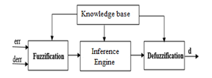 Figure 9. Fuzzy controller block diagram of the algorithm
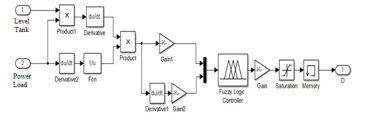 Figure 10. Simulink model of fuzzy control.
4. System and Results
All Simulation done in Simulink/MATLAB by making each component separately then combines them together. All system blocks have been studied and implemented to ensure Each part of the system block is enough precise to run the MATLAB/simulation and giving the adequate results. The PV module array for solar panels, Buck-Boost convertor with MPPT and Regulation, electrolyzer, Hydrogen tank, FC Stack, and the single-phase inverter have been created and well matched with each other. Figure 11, is showing the MATLAB/Simulink model for the whole hybrid system. The PV Array used to provide the FC system with its requirements from the power through the Electrolyzer which generate the required Hydrogen to be used as input for the Fuel Cell Stack to generate its output terminal voltage to feed the loads connected to its terminals via a single phase PWM VSI.
The maximum voltage from PV is designed to be 300 V, nevertheless the PV panel maximum power (MP) is varying due to weather, a (P&Q) MPPT algorithm is used to get the maximum power (MP) from the photo-voltaic panels via the Buck/Boost Converter. In this simulation, the photo-voltaic panels maximum voltage and current were obtained and the electrolyzer became able to generate hydrogen with maximum output. The generated Hydrogen is stored at Storage Tank which is connected to the FC Stack. The Fuel-Cell Stack when fed with the required Hydrogen level it produces its Actual output voltage which depends on the Hydrogen pressure value and its current density. The output voltage from the FCs input to a Buck-Boost DC/DC converter to step-up or down its voltage to a stabilized level suitable for the inverter input terminals. The inverter output AC voltage is used to fed the loads connected its output terminals.
Two scenarios used to examine the system. First, the design performance is observed and when the irradiance and temperature variations with and without MPPT. Secondly, the entire system performance is observed when constant irradiance (1000 W/m2) and temperature (25oC) and load variable.
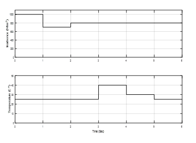 Figure 12. the irradiance and temperature variations with time
4.1. Complete System with Irradiance and Temperature Variations:
The result obtained in Figure 12, suggests that the irradiance and temperature variations.
- a) The system response without MPPT
In Figure 13, the PV voltage and Buck-Boost voltage of PV are shown. While Figure 14, is shown FC voltage and converter voltage of FC. Electrolyzer mass flow and tank mass of H2 are shown in Figure 15. Figure 16, is shown the load current and voltage.
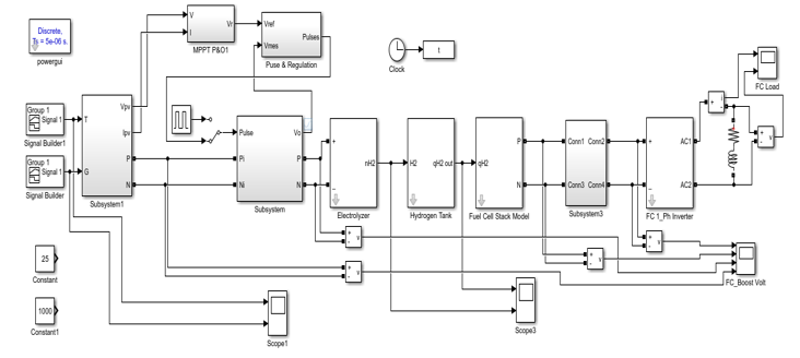 Figure 11. Simulink model for the whole hybrid system
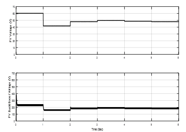 Figure 13. PV voltage and Buck-Boost voltage.
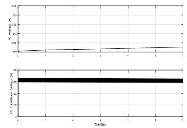 Figure 14. FC voltage and converter voltage of FC.
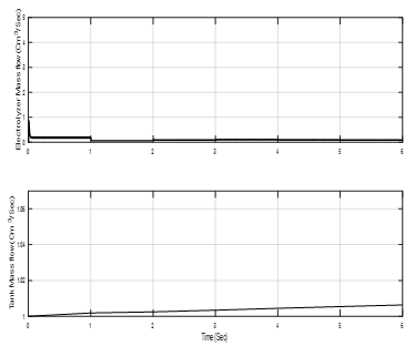 Figure 15. Electrolyzer mass flow and tank mass of H2.
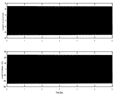 Figure 16. load current and voltage.
- b) The system response with MPPT
In this case, the PV voltage is the same in Figure 13, but Buck-Boost voltage of PV is change as shown Figure 17. It is increase with MPPT. And FC voltage and Electrolyzer mass flow are very increase than without MPPT as shown in Figure 18.
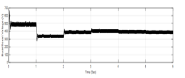 Figure 17. Buck-Boost voltage of PV with MPPT.
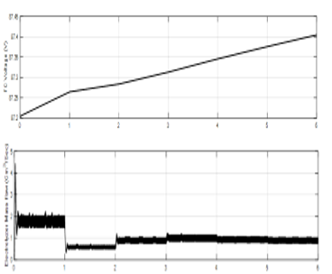 Figure 18. FC voltage and Electrolyzer mass flow with MPPT.
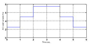 Figure 19. AC load variable with time
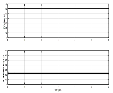 Figure 20. PV voltage and Buck-Boost voltage.
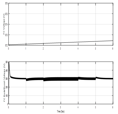 Figure 21. FC voltage and FC converter voltage.
4.2. Complete System with load demand Variation:
Complete System with constant Irradiance (1000 w/Cm2) and Temp. (25oC) and Load Variations. The load variable is shown in Figure 19.
- a) System without MPPT:
Figure 20, is shown the PV and Buck-Boost converter voltage. FC voltage and FC converter voltage are shown in Figure 21. While, Electrolyzer mass flow and tank mass of H2 are shown in Figure 22. Figure 23, is shown the load current and voltage.
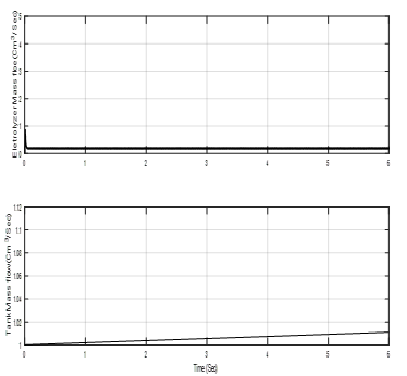 Figure 22. Electrolyzer mass flow and tank mass of H2.
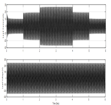 Figure 23. load current and voltage.
- b) The system response with MPPT
In this case, the Buck-Boost voltage of PV and FC voltage are shown Figure 24, Buck-Boost voltage is increase to the value of MPPT. Figure 25, is shown the Electrolyzer mass flow and tank mass flow.
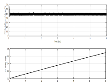 Figure 24. Buck-Boost voltage of PV and FC voltage.
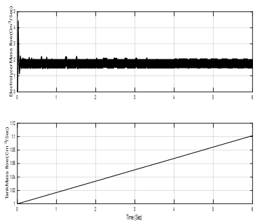 Figure 25. Electrolyzer mass flow and tank mass flow.
5. Conclusions
In this Simulation, the system of renewable energy has been developed. The photo-voltaic panels were tested in order to supply a certain load as long as it is available and to supply the Fuel-Cell System with its required power to generate the required Hydrogen value for its operation when it needed. The electrolyzer consumes some of the generated power from photo-voltaic panels. along with the system the DC/DC Buck/Boost convertor with a MPPT algorithm used to regulate and maintain the current values feeding the electrolyzer. MATLAB/Simulink used for simulation and helping to combine and integrate such hybrid systems. FLC used to model system that manages power between the level of H2 tank and the load demand. The simulation results for some models are shown which indicate the validity of the whole system.
This paper provides a system based on storing the energy by producing hydrogen to cover any feeding system when needed. Because, Photo-voltaic energy provides power in the morning, while this system provides it at any time when needed.
- Sarita Samal & Prakash Kumar Hota “Design and analysis of solar PV-fuel cell and wind energy based microgrid system for power quality improvement” Cogent Engineering, Vol. 4, No. 1, 2017. DOI :10.1080/23311916.2017.1402453
- S. Kumar Singh, C. Banerjee, “Modelling and Simulation of Hybrid Solar Cell and Fuel Cell for Suburban Electrification”, IJAREEIE, Vol. 7, Issue 5, May 2018. DOI :10.15662/IJAREEIE.2018.0705040
- Ates, S. Z. Shekardasht, E. Canli “Solar Energy Supported Hydrogen Production: A Theoretical Case Study”, Selcuk University, Selcuklu, Konya, TURKEY, 2017. DOI: 10.15317/Scitech.2017.110
- Mehran Jamshidi and Alireza Askarzadeh, “Techno-economic analysis and size optimization of an off-grid hybrid photovoltaic, fuel cell and diesel generator system” Sustainable Cities and Society, Vol. 44, No. 1, 2019, pp 310-320, DOI : 10.1016/j.scs.2018.10.021
- Juan M.Lujano-Rojas, Cláudio Monteiro, Rodolfo Dufo-López, and José L.Bernal-Agustín, “Optimum load management strategy for wind/diesel/battery hybrid power systems” Renewable Energy, Vol. 44, Aug. 2012, pp 288-295, DOI : 10.1016/j.renene.2012.01.097.
- Sumon Rashid, S. Rana, S.K.A. Shezan, Sayuti A.B. Karim, and Shamim Anower “Optimized design of a hybrid PV wind-diesel energy system for sustainable development at coastal areas in Bangladesh” Environmental Progress & Sustainable Energy, Vol. 36, No. 1, 2017, pp 297-304, DOI : 10.1002/ep.12496.
- P. K. Goel, B. Singh, S. S. Murthy, N. Kishore, “Isolated wind-hydro hybrid system using cage generator and battery storage”, IEEE Transactions on Industrial Electronics, Vol. 58, pp. 1141-1153, 2011. DOI: 10.1109/TIE.2009.2037646
- Iman Edwar, and Maged. N. F. Nashed “Solar and Wind Energy for Hybrid Electric Vehicle Controlled with Bi-directional DC/DC Converter System” 3rd International Conference on Advaced Control Circuits and Systems, (ACCS’013), Luxor, Egypt, Nov. 30 – Dec. 3, 2013.
- T. Bogaraj, J. Kanakaraj, and J. Chelladurai, “Modeling and simulation of stand-alone hybrid power system with fuzzy MPPT for remote load application,” Archivals of Electrical Engineering, Vol. 64, No. 3, pp 487-504, DOI : 10.2478/aee-2015-0037, 2015.
- M. Idrees et al., “Fuzzy Logic Based Calculation and Analysis of Health Index for Power Transformer Installed in Grid Stations,” in 2019 International Symposium on Recent Advances in Electrical Engineering (RAEE), 2019, vol. 4, pp. 1–6.
- Ehab M. Zakaria, Shawky H. Arafa, Maged M. N. F. Nashed, and Salah G. Ramadan “Dynamic Analysis of Photovoltaic-Fuel Cell-Electrolyzer System at Stand Alone Operation” International Journal of Engineering and Innovative Technology (IJEIT) Volume 8, Issue 11, May 2019, pp: 7-12
- S. Z. Hassan, H. Li, T. Kamal, F. Mehmood, “Fuzzy embedded MPPT modeling and control of PV system in a hybrid power system” 12th International IEEE Conference on Emerging Technologies (ICET) 18-19-October 2016, DOI: 10.1109/ICET.2016.7813236
- T. Kamal, S. Z. Hassan , M. Espinosa-Trujillo, H. Li, M. Flota, “An Optimal Power Sharing and Power Control Strategy of Photovoltaic/ Fuel Cell/Ultra-capacitor Hybrid Power System” Journal of Renewable and Sustainable Energy Vol. 8, No. 3, 2016. DOI: 10.1063/1.4948926