Performance of a Thermoelectric Powered by Solar Panel for a Large Cooler Box
 , Syahrul Syahrul 1, Made Wirawan 1, I Made Adi Sayoga 1, Agung Tri Wijayanta 2, Ilham Mahyudin 1
Adv. Sci. Technol. Eng. Syst. J. 5(1), 325–333 (2020);
 DOI: 10.25046/aj050141
An experiment to determine the performance of a thermoelectric powered by solar panel for a large cooler box was carried out. The size of the cooler box tested was 1000 mm x 500 mm x 400 mm and inside the cooler box, a plastic bottle containing 19 liters of water was placed. The thermoelectric hot side was cooled using a mini channel flowed with water. Meanwhile, the cold side of the thermoelectric was connected to the inner heat sink to absorb heat inside the cooler box. The thermoelectric was powered from a battery charged by solar panels directly. There were 2 solar panels, each of which had a power of 100 WP. The cooler box was tested for 6 days in June 2019. The results showed that the lowest temperature on the thermoelectric cold side was around 16.21°C, while the lowest temperature inside the cooler box was 24.25°C. The experimental COPs obtained were ranging from 0.01 to 0.76. Moreover, in general, solar panels were potential as power sources for thermoelectric cooling systems.
1. Introduction
Portable refrigerators are sometimes very necessary, especially in a place far from home or for transportation of goods, blood, and vaccines. For the purposes, thermoelectric cooling machines can be an option because thermoelectric cooling machines are more compact, with no leakage problems, lighter, portable, easier to maintain and more durable as reported in [1- 6]. Nevertheless, the weakness of the thermoelectric is low COP, even less than 1.
There are several ways to raise the COP such as improving the quality of thermoelectric materials, varying the use of thermoelectric techniques, and engineering the dissipation units. The research on thermoelectric materials also has been increased to obtain material that can generate higher COP. But in the term of materials, the thermoelectric development is slow, therefore, attempts to increase the COP through applications have been also tried, one of which is the application to cool beverage cans as reported in [7].In [7], the authors elucidated that thermoelectric applications to cool beverage cans commonly produced temperatures of 6-8°C within 2 hours. However, the COP of this cooling system was still less than 1, which was 0.856 and could not reach a temperature of 0°C. The authors in [8] investigated the application of thermoelectric modules as a beverage cooler box. They used 2 and 3 thermoelectric modules with a fan or without a fan and a capacity of 34 liters. The beverage cooler box was run for 150 minutes and they obtained a minimum temperature of 14.3°C without water and 16.4°C with 1 liter of water.In [9], the author examined a thermoelectric refrigerator with 3 thermoelectric modules and power of 51.27 W. The temperature of the refrigerator reached of around 14°C with a drinking water of 1500 ml, while the COP obtained was 0.25. However, even from the engineering side, the application of thermoelectrics is still difficult to obtain high COP. Therefore, this study tries to use a heat dissipation unit that is different from previous studies.In general, research on the use of thermoelectric cooling modules was carried out using a fin-fan heat sink heat dissipation unit. In [4], authors conducted a study of two different heat dissipation units namely the fin-fan heat sink and the double fan heat pipe. They concluded that with a double fan heat pipe, the cooling box performance including the COP increased. However, the power used by the double fan heat pipe also increased. If the electrical energy consumed by the double fan was taken into account, the heat sink fin-fan unit was superior. Therefore, it is necessary to look for other heat dissipation units such as water heat exchangers.The water heat exchangers such as a water block used for removing heat from the hot side of thermoelectrics had been studied in [10]. Apparently, the water block was still not effective because the ability to transfer heat was still low. Water heat exchangers that might be able to increase COP are mini-channel or mini-pin fin. Why a mini channel is predicted to be able to increase COP? Based on the previous research, mini-channel has been presenting to have a higher heat transfer ability compared to other water heat exchangers as reported in [11]. Similarly, the mini pin fin heat exchanger had been tested to be able to transfer more heat as explained in [12].Furthermore, COP is also influenced by the size of the refrigerator. A large refrigerator increases the COP and the temperature. Nevertheless, the high refrigerator temperature means that the cooling process is not adequate. Likewise, vice versa, a small refrigerator produces a small COP and a low temperature. However, the effect of refrigerator size is unclear for the refrigerator with a large mass of goods. The more mass in the refrigerator, the higher COP and temperatures as explained in [5]. Table 1 shows several sizes of cooler boxes that have been studied. In Table 1, the largest refrigerator/cooler box size studied is 620 mm x 595 mm x 1565 mm. The refrigerator was examined in [15]. However, they used 8 thermoelectric modules.Power for thermoelectric refrigerators is generally obtained from conventional electric grids. However, in Indonesia, the price of electricity is still relatively high and the availability of electricity has not been fully distributed to remote areas and small islands yet. Therefore, this study uses electricity sources obtained from solar panels. Even so, this paper does not discuss solar panels in detail because the solar panels are only used as the DC power source.This research has the advantage of overcoming the urgent problem: (i) the supply of fossil fuels is almost gone, so all electrical equipment including refrigerators may be operated with renewable energy, (ii) introducing new cooling methods that do not require large and expensive equipment, (iii) thermoelectric cooler boxes with mini-channel heat dissipation units have not been widely studied. The purpose of this study is to examine the performance of a large refrigerator using a single thermoelectric module powered using solar panels. The thermoelectric hot side is cooled utilizing a water mini-channel. The characteristics of the refrigerator are represented by the lowest temperatures that can be achieved and the COP. The contribution of this research to the thermoelectric study field is to increase the information concerning thermoelectric usages for cooler boxes.
2. Research Method
2.1. Experimental Set-up
This work was experimental research using a test rig as shown in Figure 1 consisting of a cooler, a thermoelectric, solar panels, water, a mini-channel, a pump, a small radiator, a small tank, a flow meter, a battery, a solar charger, and a data logger National Instrument (NI9714). All temperatures were measured using K type thermocouples calibrated with an accuracy of ± 0.5°C. The electrical power used was measured using a Vichy Vc8145 digital multimeter, while the flow of the water passing through the mini-channel was measured using an FLR1000 flowmeter with an accuracy of ± 0.2 g/s.
When the electric current was supplied to the thermoelectric, the thermoelectric hot side temperature increased drastically. This increased temperature should be maintained so that it did not exceed 40°C, i.e. using water flow. Finally, the heat from the thermoelectric was carried away by the flow of water towards the small radiator. Inside the small radiator, the heat was discharged into the environment through the radiator walls. Then the water returned to the small tank. The electricity used fluctuated because the source was solar panels. When the sun was bright, the power was great and vice versa. However, these fluctuations could be prevented using a battery.
Table 1: Sizes of cooler boxes that had ever been studied, heat dissipation units, and COPs
| Reference | Size | Heat dissipation unit | COP |
| [1] | 180 mm x 230 mm x 320 mm | Heat sink with a fan | 0.16 |
| [3] | – | Heat sink with a fan | Decrease with difference temperature |
| [4] | 285 mm x 245 mm x 200 mm | Heat sink with a fan, and double fan heat pipe | 0.002-0.02 |
| [7] | 16 mm x 8 mm x 9 mm | Heat sink with a fan | 0.856; 0; 731 |
| [8] | 500 mm x 315 mm x 291 mm | Heat sink with a fan | – |
| [13] | – | Heat sink with a fan | 0.43-0.45 |
| [14] | 250 mm x 250 mm x 350 mm | Heat sink with a fan | 0.65 |
| [15] | 620 mm x 595 mm x 1565 mm | Heat sink, big aluminum | 0.58 |
| [16] | 1. 65 mm x 70 mm x120 mm.
2. 55 mm x 57 mm x 140 mm 3. 100 mm x 100 mm x 230 mm 4. 60 mm x 65 mm 150 mm 5. 80 mm x 75 mm x 170 mm |
Heat sink with a fan | – |
| [17] | – | Heat sink with fan | 0.03-0.194 |
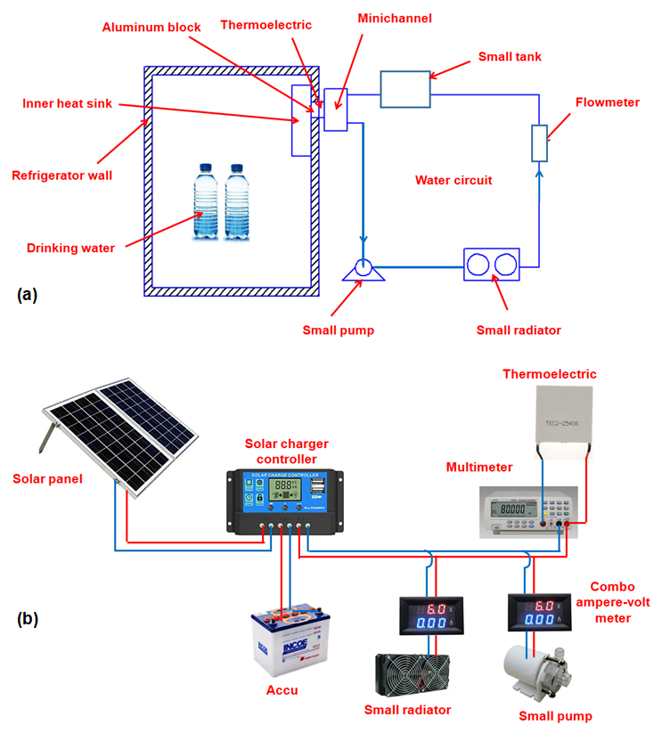 Figure 1: Schematic diagram of the research apparatus; (a) refrigerator and water circuit, (b) electrical circuit.
Thermocouple placements can be seen in Figure 2. The thermocouple locations are denoted using letters a-q. The solar panels used were two pieces with each power of 100WP, and the battery employed was a dry (free maintenance) battery with a voltage of 12 V and a current of 100 AH. However, the analysis here is focused on the performance of the refrigerator only and deep analysis of the mini-channel is not given in this paper.
2.2. Heat Transfer Analysis
The experimental data were analyzed using various equations to determine the performance of the refrigerator. All parameters of the research were analyzed to obtain conclusions. The heat balance in the thermoelectric can be estimated using equation (1) which can be obtained in [14].
![]() Qh is the heat released on the hot side of the thermoelectric (W), Qc is the heat absorbed on the cold side of the thermoelectric (W) and Pin is the input power (W).
Qh is the heat released on the hot side of the thermoelectric (W), Qc is the heat absorbed on the cold side of the thermoelectric (W) and Pin is the input power (W).
In the design of thermoelectric refrigerators, there were two types of heat loads that should be overcome, namely (i) the heat load from the air and the items in the refrigerator, and (ii) the heat load entering through the walls of the cooler box. The equation to determine the heat load from air and goods can be seen in [4-6, 18-19], which can be expressed in the equation as follows:
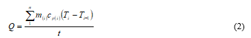 Q is the heat load and is defined as the total heat coming from the goods inside the cooler box (W). m(i) is the momentary mass (kg), cp(i) is the momentary specific heat of the goods (J/kg K) and T(i) represents the momentary temperature (°C), while t is the total time of the running machine (s). Whereas heat entering through the refrigerator wall that is called conduction can be estimated by the equation that can be found in [20].
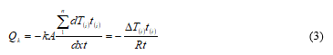 Qk is the conduction heat transfer rate (W), k is thermal conductivity (W/m°C), A denotes heat transfer area (m²), and dT(i) /dx is the instantaneous temperature gradient over a distance (°C/m). ΔT(i) is the instantaneous temperature difference of the hot and cold surface temperatures (°C), while R is a thermal resistance (°C/W). Total cooling capacity can be determined by the equation that can be obtained in [18].
![]() Qc is the total cooling load (W), and the COP of the refrigerator can be computed using equation (5) that can be attained in [21]:
Qc is the total cooling load (W), and the COP of the refrigerator can be computed using equation (5) that can be attained in [21]:
![]() The Pin is all power given to the refrigerator system including the power given to the thermoelectric, to the pump, and to the small radiator. V is the voltage, and I is the current. The thermoelectric hot side was cooled using a mini-channel, in which water flowed. To flow the water, a mini pump was installed on the system, and the pump required electrical power as well. In addition to the pump, the small radiator also required power, because this small radiator utilized two fans, which were driven by DC electricity. So the total power used was the sum of the thermoelectric power, pump power, and small radiator power. COP was the comparison of QC to total power as shown in equation (5). All power was taken from a battery, and the battery was filled by solar panels.
The Pin is all power given to the refrigerator system including the power given to the thermoelectric, to the pump, and to the small radiator. V is the voltage, and I is the current. The thermoelectric hot side was cooled using a mini-channel, in which water flowed. To flow the water, a mini pump was installed on the system, and the pump required electrical power as well. In addition to the pump, the small radiator also required power, because this small radiator utilized two fans, which were driven by DC electricity. So the total power used was the sum of the thermoelectric power, pump power, and small radiator power. COP was the comparison of QC to total power as shown in equation (5). All power was taken from a battery, and the battery was filled by solar panels.
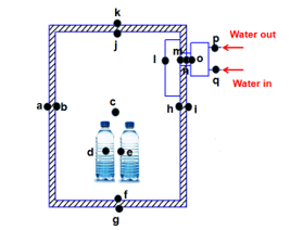 Figure 2: Thermocouple locations are marked with the letter a-q
3. Results and Discussion
The results of the study were presented in the form of graphs and tables. Before the results of the experiments were presented, the recorded temperature results were given in Figure 3 for 6 days. The purpose of presenting this figure was to see the temperature trend and the temperature differences for 6 days.
The thermoelectric hot side temperature increased drastically and then flattened out. This was because heat, Qh, came out from the thermoelectric hot side. This was also observed by several previous researchers, e.g. [1, 4-6, 14, 22]. Meanwhile, the thermoelectric cold side temperature dropped dramatically and then flattened out. The thermoelectric cold side temperature trend also showed a similar trend, but the room temperature was higher than the thermoelectric cold side temperature. This was because the heat transferred from the room to the cold side of the thermoelectric went through a long connector. In the connector, there could be other heat coming from the surrounding, and then the heat absorbed in the cooler box room was lower than the heat absorbed by the cold side of the thermoelectric.
From the air in the refrigerator, the heat was absorbed by the inner heat sink. From the inner heat sink, the heat went through an aluminum block to arrive at the surface of the thermoelectric cold side. However, at the same time, there was the heat that entered through the refrigerator wall. The heat might come to the connector as well. As a result, the cold side of the thermoelectric was unable to absorb much heat from the refrigerator because it had gained additional heat at the connector.
From the cooler box temperature, water temperature, and bottle temperature, then the total heat that should be removed from inside the cooler box could be estimated. The estimation of heat transfer from air, water, and bottles can be done using equation (2). The results of the experiment showed that the heat taken from the air, from water, and from the bottle decreased with time, and then flattened out, see Figures 4-7. This was because the heat inside the cooler box could not be absorbed anymore after several seconds. The thermoelectric capability was maximal in these conditions. However, such things were also obtained by previous researchers such as [4-6, 14, 23]. The parameter used to indicate the performance of the cooler box was COP. COP could be determined using equation (5). The COP trend decreased with time. In the initial seconds, the COP was very high, then the COP dropped continuously over time, see Figure 10.This COP trend was also found by some previous researchers such as [13-14, 22, 24-26]. In [26], the authors drained water on the thermoelectric hot side using a mini-channel. However, they used conventional electricity sources and many thermoelectric modules, while in this experiment, the electrical power was taken from solar panels and the thermoelectric module used was only one. How to flow water in [26] was also different from this study.They flowed water from the reservoir to the pump, to the thermoelectric hot side, to the heat exchanger (small radiator), and back to the reservoir. In this study, the water was flowed from the reservoir to the thermoelectric hot side, to the pump, to the small radiator and back to the reservoir. So the difference was the location of the pump installed on the system/ test rig.
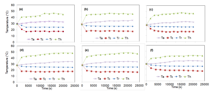 Figure 3: Trend of temperatures with time for 6 days; (a) day 1, (b) day 2, (c) day 3, (d) day 4, (e) day 5, (f) day 6.
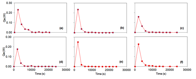 Figure 4: Calculated heat absorbed from the air inside the refrigerator; (a) day 1, (b) day 2, (c) day 3, (d) day 4, (e) day 5, (f) day 6.
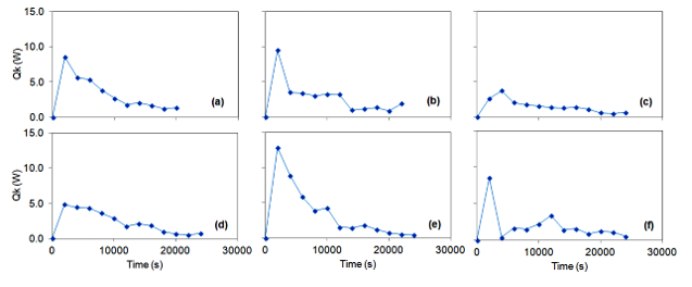 Figure 5: Trends of the conduction heat transfer rate with time; (a) day 1, (b) day 2, (c) day 3, (d) day 4, (e) day 5, and (f) day 6
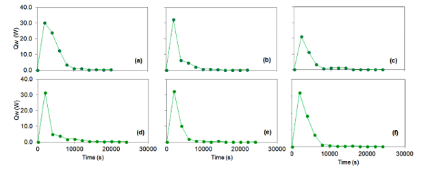 Figure 6: Trends of the heat transfer rate absorbed from the water respect to time; (a) day 1, (b) day 2, (c) day 3, (d) day 4, (e) day 5, and (f) day 6
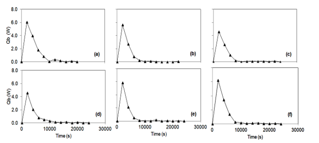 Figure 7: Trends of the heat transfer rate absorbed from the plastic bottle with time; (a) day 1, (b) day 2, (c) day 3, (d) day 4, (e) day 5, and (f) day 6
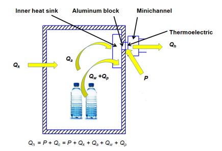 Figure 8: Illustration of heat flows in the refrigerator system for this study
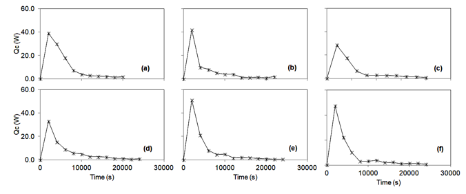 Figure 9: Trends of total heat transfer rate that should be removed from inside the refrigerator with time; (a) day 1, (b) day 2, (c) day 3, (d) day 4, (e) day 5, and (f) day 6
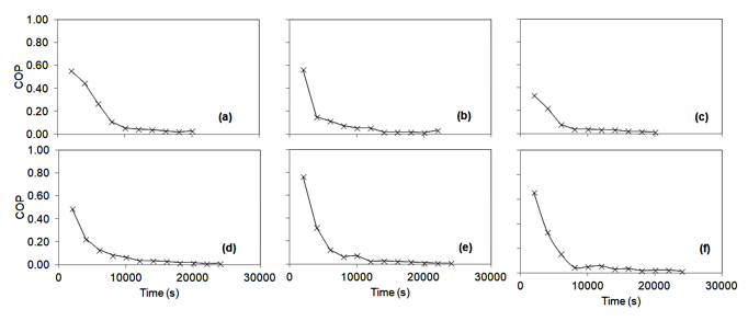 Figure 10: Trends of the COP with time; (a) day 1, (b) day 2, (c) day 3, (d) day 4, (e) day 5, and (f) day 6
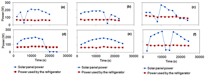 Figure 11: Solar panel power and power used by the refrigerator with time
From the character of the refrigerator mentioned above, the most interesting thing was the relation of the character to the output power of the solar panel. The output power of the solar panels during the study was recorded and shown in Figure 11. The power of solar power increased with time and finally after reaching its peak it dropped again. However, solar panel power was very dependent on sky conditions. If the sky was suddenly cloudy, the solar panel power went down and vice versa. Therefore, the increase in solar panel power was uncertain. Besides that, in this study, the solar panel power was determined as the multiplication of solar power and solar panel area. Furthermore, the multiplication results were then multiplied by the efficiency of solar panels which in general was around 20%. Apparently, fluctuations in solar panel power did not affect the power used by the refrigerator. This was because the output of the solar panel was connected to the battery so that the fluctuations could be muted by the battery. The number of solar panels used was 2 pieces, and each had a power of 100 WP, so the total power was around 200 WP. The power output was apparently less than 200 W as shown in Figure 11.
4. Conclusion
An experimental study to measure the performances of thermoelectric powered using solar panels for cooling a big cooler box was conducted. The cooler box had one thermoelectric module. The air temperature inside the cooler box was still high. One thermoelectric was not adequate for cooling purposes for a big cooler box. The number of thermoelectrics installed should be more than 1 in order to fulfill the cooling purposes. Due to the battery, the fluctuation of the solar panel output became collapse and the power absorbed by the thermoelectric was stable for about 25200 s. In general, the solar panel could be used for powering the thermoelectric cooler box, but one module was not enough for a big box.
Conflict of Interest
The authors declare no conflict of interest.
Acknowledgment
The authors would like to acknowledge the DRPM for the funding through the research PDUPT schema.
Nomenclature
A cross-sectional area (m²)
cp specific heat (J/kg°C)
COP coefficient of performance
dT temperature difference (°C)
dx distance (m)
I current (A)
m mass (kg)
Q heat transfer rate (W)
R thermal resistance (°C/W)
t time (s)
T temperature (°C)
P power (W)
V voltage (V)
ΔT temperature change, temperature difference (°C)
Subscript
a air
c cold
h hot
in input
k conduction
p plastic bottle
w water
- S.A. Abdul-Wahab, A. Elkamel, A.M. Al-Damkhi, I.A. Al-Habsi, H.S. Al-Rubai’ey’, A.K. Al-Battashi, A.R. Al-Tamimi, K.H. Al-Mamari, M.U. Chutani, “Design and Experimental Investigation of Portable Solar Thermoelectric Refrigerator” Renewable Energy, 34, 30-34, 2009. https://doi.org/10.1016/j.renene.2008.04.026
- M.K. Rawat, H. Chattopadhyay, S. Neogi, “A Review on Developments of Thermoelectric Refrigeration and Air Conditioning Systems: A Novel Potential Green Refrigeration and Air Conditioning Technology” Int. J. Engineering Technology and Advanced Engineering, 3(3), 362-367, 2013.
- N.J.M. Reddy, “A Low Power, Eco-Friendly Multipurpose Thermoelectric Refrigerator” Front. Energi, 10(1), 79-87, 2016.
https://doi.org/10.1007/s11708-015-0380-8 - Mirmanto, I.B. Alit, I.M.A. Sayoga, R. Sutanto, Nurchayati, A. Mulyanto, “Experimental Cooler Box Performance Using Two Different Heat Removal Units: A Heat Sink Fin-Fan, and a Double Fan Heat Pipe” Frontier in Heat and Mass Transfer, 10(34), 1-7, 2018. http://dx.doi.org/10.5098/hmt.10.34
- M. Mirmanto, I.W. Joniarta, I.M.A. Sayoga, N. Nurpatria, Y.A. Padang, I.G.N.K. Yudhyadi, “Effect of Water Volume on a Thermoelectric Cooler Box Performance” Frontiers in Heat and Mass Transfer, 11(17), 1-9, 2018. http://dx.doi.org/10.5098/hmt.11.17
- M. Mirmanto, S. Syahrul, Y. Wirdan, “Experimental performances of a thermoelectric cooler box with thermoelectric position variations” Engineering Science and Technology, an International Journal, 22, 177–184, 2019. https://doi.org/10.1016/j.jestch.2018.09.006
- B. Irwin, A. Ruri, “Kaji Eksperimental Kotak Pendingin Minuman Kaleng dengan Termoelektrik Bersumber Dari Arus Dc Kendaraan dalam Rangkaian Seri dan Paralel”, Seminar Nasional Tahunan Teknik XII, Bandar Lampung, 2013.
- A. Aziz, S. Joko, S. Villager, “Aplikasi Modul Pendingin Termoelektrik Sebagai Meia Pendingin Kotak Minuman” Jurnal Teknik Mesin Universitas Riau, 32-38, 2014.
- G. Ramdhan, “Sistem Pendinginan pada Kulkas Termoelektrik dengan Variasi Pembebanan” Skripsi, Jurusan Teknik Mesin, Fakultas Teknik, Universitas Mataram, Mataram, NTB, Indonesia, 2016.
- D.K. Putra, “Unjuk Kerja Kotak Pendingin Termoelektrik dengan Variasi Laju Aliran Massa Air Pendingi” Skripsi, Jurusan Teknik Mesin, Universitas Mataram, 2018.
- J. Hejcik, M. Jicha, “Single-Phase Heat Transfer in Minichannels” EPJ Web of Conference, 67, 1-4, 2014.
http://doi.org/10.1051/epjconf/20146702034 - T. Yeom, T. Simon, T. Zhang, M. Zhang, M. North, T. Cui, “Enhanced Heat Transfer of Heat Sink Channels With Micro Pin Fin Roughened Walls” Int. J. of Heat and Mass Transfer, 92, 617–627, 2016.
https://doi.org/10.1016/j.ijheatmasstransfer.2015.09.014 - M. Gillott, L. Jiang, S. Riffat, “An Investigation of Thermoelectric Cooling Devices for Small-Scale Space Conditioning Applications in Buildings” International Journal Of Energy Research, 34, 776-786, 2010.
http://doi.org/10.1002/er.1591 - S. Jugsujinda, A. Vora-ud, T. Seetawan, “Analysing of thermoelectric refrigerator performances” Procedia Engineering, 8, 154-159, 2011. https://doi.org/10.1016/j.proeng.2011.03.028
- K. Atik, Y. Yildiz, “An Experimental Investigation of a Domestic Type Solar TE Cooler” Energy Sources, Part A, 34, 645–653, 2012.
http://dx.doi.org/10.1080/15567031003627989 - A. Aziz, R.I. Mainil, A.K. Mainil, Syafri, M.F. Syukrillah, “Design of Portable Beverage Cooler Using One Stage Thermoelectric Cooler (TEC) Module” Aceh Int. J. Sci. Technol., 7(1), 29-36, 2017.
http://doi.org/10.13170/aijst.6.1.5427 - D. Suryawanshi, N. Pokharkar, V. Pokale, A. Walgude, “Design and Fabrication of Thermoelectric Refrigerator for Liquid Cooling by Automatic Temperature Micro-Controller” International Journal of Science Technology & Engineering, 3, 21-27, 2016.
- F. Incropera, D.P. DeWitt, T.L. Bergman, A.S. Lavine, “Fundamentals of Heat and Mass Transfer, 6th Edition, John Wiley & Sons, Hoboken, 2006.
- H.P. Banjarnahor, “Analisis Laju Pendinginan pada Kulkas Thermoelektrik Super Cooler Dibandingkan Sistem Pendingin Konvensional Menggunakan Gas Freon” Skripsi, USU Institutional Repository, Universitas Sumatera Utara, 2016.
- A. Waleed et al., “Solar (PV) Water Irrigation System with Wireless Control,” in 2019 International Symposium on Recent Advances in Electrical Engineering (RAEE), 2019, vol. 4, pp. 1–4.
- Y.A. Cengel, M.A. Boles, “Thermodynamics an Engineering Approach”, 6th Ed., McGraw-Hill Higher Education, Boston, 2008.
- S.M. Hafis, M.J.M. Ridzuan, A.Z.A. Firdaus, S.M. Shahril, R.N. Farahana, C.A. Chong, “COP Improvement of Thermoelectric Cooler Through the Optimization of Heat Dissipation System” Applied Mechanics and Materials, 554, 241-245, 2014. https://doi.org/10.4028/www.scientific.net/AMM.554.241
- H. Ananta, Mirmanto, Y.A. Padang, “Unjuk Kerja Kulkas Termoelektrik dengan Rangkaian Seri dan Parallel pada Beban Air 1500 ml” Dinamika Teknik Mesin, 7(2), 80-86, 2017. https://doi.org/10.29303/dtm.v7i2.157
- B.J. Huang, C.J. Chin, C.L. Duang, “A Design Method of Thermoelectric Cooler” International Journal of Refrigeration, 23, 208-218, 2000.
https://doi.org/10.1016/S0140-7007(99)00046-8 - H. A. Raza, M. T. Riaz, M. Idrees, M. M. Afzal, W. S. Hashmi, and M. W. Asif, “Analysis the effect of 500kv High-Voltage Power Transmission Line on the Output Efficiency of Solar-Panels,” in 2019 International Conference on Electrical, Communication, and Computer Engineering (ICECCE), 2019, pp. 1–6.
- M. Gökçek, F. Şahin, “Experimental Performance Investigation of Minichannel Water Cooled-Thermoelectric Refrigerator”, Case Studies in Thermal Engineering, 10, 54-62, 2017. https://doi.org/10.1016/j.csite.2017.03.004