Effects of Split Ring Resonator (SRR) Metamaterial on the Radiation Pattern and Variation of the Heating Focus Point of the Microstrip Patch Antenna

Adv. Sci. Technol. Eng. Syst. J. 5(1), 307–316 (2020);
 DOI: 10.25046/aj050139
Metamaterial antennas are some sort of antennas which utilize metamaterials to improve the efficiency of small (small electrical) antenna systems and also enhance the antenna’s radiation pattern. The unusual properties of metamaterials such as coefficients of permittivity and permeability, as well as the negative refractive index, have led to increase the use of these artificial materials in variant fields including microwave engineering and medical applications. This paper explores a metamaterial coating and impact of it on a microstrip patch antenna from two different perspectives on satellite and biomedical applications. For this purpose, a microstrip antenna is modeled using CST software and then a particular metamaterial cover is configured upon the patch antenna to enhance its efficiency such as radiation pattern and directivity. The method is arranged in several stages and the output of the antenna is then analyzed in each stage after applying some adjustments to the design process. On the other hand, because the type and position of the applicator on the tissue is a consequential variable, in order to improve the effectiveness of hyperthermia treatment in medical applications, in the next step the metamaterial antenna is applied to hyperthermia treatment on the body tissue. Eventually the results of metamaterial antenna are compared with the usual antenna.
1. Introduction
Current paper is an extended version of work originally presented in [1].
Veselago first proposed the concept of the negative refractive index and the presence of substances with this feature in 1968 [2]. By using a wired structure John Pandari succeeded in achieving negative permittivity in 1996, and by using split resonator rings, he then prospered independently in generating an ambit with negative permeability in 1999 [3]. The idea was fulfilled experimentally and actually in 2000 by David Smith and his fellow members, applying an intermittent volumetric series of alternative metal wires and split ring resonator combinations [4,5]. The name given to these materials is “Metamaterial”.
Since the metamaterials have the negative ε and µ, n has a negative root in certain frequencies which is formulated by Maxwell equation that is [6]. The peculiar and appealing features of these materials have contributed to their usage in diverse fields, such as microwave engineering, waveguide operation, phase compensation, dispersion correction, smart new antennas, lenses and numerous other instances. A type of metamaterial structure and its impacts on performance of a microstrip antenna will be studied in this article.
If an electrical field is applied in parallel to a structure composed of a series of thin metal rods, a negative permittivity property will be revealed in the structure. Likewise, if a magnetic field is perpendicularly exerted to a mechanism with a set of split ring resonators (SRR), it will exhibit a negative permeability [7].
The Microstrip Antenna Concept was first presented in 1950 [8]. The reasons for its success were proper characteristics including lower volume, light weight, low expense and reasonable efficiency [9,10]. A plan is proposed in this paper that using it we will explore the capacities as well as restrictions of metamaterial mechanism in antenna design.
The standard microstrip antenna is formed of three segments of ground, a radiation surface and, a dielectric substrate. This dielectric substratum lies between the patch (radiation surface) and the ground layer.
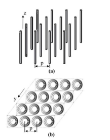 Figure 1: An illustration of intermittent patterns. (a) The metal thin rods, (b) The split ring resonators (SRRs)
Equations (1), (2), (3), (4) and (5) measure the sizes of a standard patch, where W and L are width and length of the radiation patch, respectively [9,11].
The theory of the effective quantity has been used here. We need data of the scattering parameters ( and ) for a wave incident normally on a finite slab of a homogeneous material, to recover its electromagnetic characteristics including analytical quantities of permeability (µ) and permittivity (ε), that express a straightforward description. S11 and S21 are measured via (6) and (7) [12]:
Also the permeability and permittivity are computed by the relations μ = nz and ε = n / z [12, 13].
As it is evident, scattering parameters are correlated with ε and µ, and also with n and z. Hence, by inverting the S-parameters, the refractive index (n) and impedance (z) would be derived. For the calculation of n and z, equations (8) [13] and (9) are used [14]:
In which k= indicates the wave number of free space and d is the slab thickness [12].
- Overview of hyperthermia
Cancer rates are increasing alarmingly all around the world, and this matter is a major cause of concern for the medical community [15]. Cancer tumors are able to affect different tissues and spread to different body organs. In recent years, in order to deal with the disease, researchers have developed a variety of treatments, including surgery, chemotherapy, radiotherapy, immunotherapy, stem cell transplant, and targeted therapies. Beside these methods, another well-known method called hyperthermia (or heat treatment) has recently been evaluated in clinical trials. Hyperthermia is a treatment method in which tumor tissues are exposed to high temperatures to be eliminated, without affecting healthy tissues [16]. Hyperthermia can be performed in both invasive and non-invasive methods. The non-invasive hyperthermia treatment is an efficacious safe treatment with less pain and injury to counteract different types of cancer [17]. One of the biggest challenges in the non-invasive treatment of the hyperthermia, is the concentration of electromagnetic energy on the cancerous tissue in a way that not to damage to healthy tissues. In this treatment, it is required that the temperature of the treated area be raised from 35 ° C to about 42 to 45 ° C [16]. During the period of hyperthermia treatment, tumor cells are exposed to a temperature of about 42 ° C for an hour or even longer [15]. Hence, many researchers have recently focused on non-invasive hyperthermia antennas and applicators. The applicator has been considered as the principal part of the hyperthermia which uses electromagnetic energy to be transmitted and distributed in the form of heat. It is then absorbed by cancer tissues to a certain level of heat and time [17].
- SAR in hyperthermia
The quantity that is investigated in hyperthermia topic, is a parameter called specific absorption rate (SAR). The SAR quantity represents the quantity of heat energy absorbed by living tissue per unit time, when the rise of body temperature due to an external heat source exceeds one degree celsius. Specific absorption rate is defined as the energy absorbed per unit mass of tissue in watts per kilogram by (10):
The SAR measurement can also be expressed in terms of the tissue temperature rise by (11):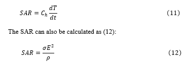
which in the (10), (11) and (12), E is intensity of the electric field in the tissue with unit of volt/meter, σ is conductivity of tissue liquid with unit of Siemens per meter, ρ is volumetric density of tissue with unit of kg/m3, is specific heat capacity of tissue with unit of J/kg and Kelvin, dT/dt is primary time derivative of tissue temperature in Kelvin unit. Therefore, SAR is calculated by measuring the amplitude of the electric field intensity [18].
2. Methodology
2.1. Original thought behind current study
This article’s original concept was taken from [19]. A microstrip patch antenna was proposed in the aforesaid paper, the radiation pattern was then ameliorated with the help of a metamaterial coating composed of split ring resonators (SRR) and wires that generate negative permeability and permittivity. Table 1 represents the findings of the above-mentioned paper.
It is worth mentioning that the SRR (Split-Ring Resonator) unit cell structure was derived from [20]. The distinction between them is that the unit cell was regarded as a singular square in the mentioned article while it is constructed from a couple of squares adjacent to one another in the present study.
Table 1: Compared results in paper [19] between the usual patch antenna and the metamaterial antenna
| Parameters | Usual patch antenna | Metamaterial antenna |
| Return losses (dB) | -30 | -23 |
| Gain(dB) | 6.80 | 7.32 |
| HPBW(3dB) |
2.2. Stages of configuration of the metamaterial antenna
To obtain the desired frequency in the 8-12 GHz range, the patch measurements (L × W) are calculated as (11.86 mm × 9.06 mm) and for the ground sizes (Lg × Wg) are measured as (21.34 mm × 18.54 mm). The frequency of resonance for the proposed antenna is 9.6 GHz [1].
The coaxial cable has been considered as the feeding of the aimed Microstrip patch antenna. In order to properly match with the input impedance, coaxial feeding can be positioned within the patch at any point [10]. To determine the location of the coaxial cable precisely, the input impedance is adjusted to: by 50 ohms.
Figure 2 displays a general form of an ordinary rectangular patch antenna which is stimulated by coaxial line.
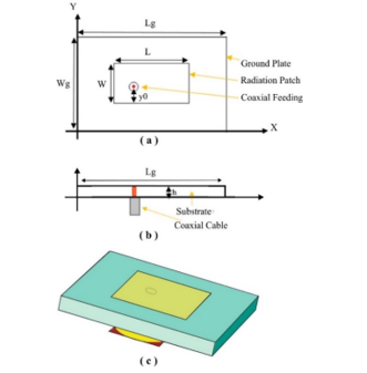 Figure 2: The microstrip patch antenna designed for 9.6 GHz. (a) Top-view geometry, (b) Side-view geometry, (c) Software-designed antenna
 Figure 3: The metamaterial-coated microstrip patch antenna
The dielectric segment of the antenna has been constructed of Epsilon 2.2 substratum of Teflon and 1.58 mm thickness. Copper has been used to make the ground plane and radiation patch. In this paper, a cover of metamaterial has been utilized over a patch antenna as shown in Figure 3. This design forms of a 0.5 mm Teflon sheet of epsilon 2.2, which has 5*3 periodic slotted rings printed on the surface of this Teflon coating (single layer) measuring 0.017 mm thick and built of copper. This system consists of simple elements which are extremely expandable. The metamaterial layer is positioned from the patch of antenna at a distance of hm=10.53 mm, which is an air gap. This air distance was assumed to be zero at first, and the metamaterial was located directly on the antenna. Then in order to compare the changes, an air distance between the antenna and the metamaterial was regarded. The comparisons and findings have been provided in the section 3. In another phase, the SRR’s intermittent configuration was arranged in two layers which were mounted on both sides of the Teflon coating surfaces in equal numbers. The findings have been analyzed in section 3 and compared to the singular layer SRR type. During other stage, we modified the unit cells and attained new results. At the end, the function of metamaterial antenna in hyperthermia treatment, has been investigated.
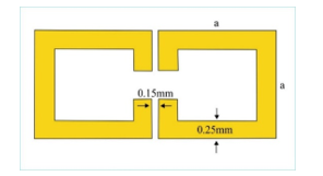 Figure 4: The designed SRR unit cell
Figure 3 displays the common microstrip antenna with the placement of metamaterial cover and Figure 4 illustrates the unit cell of SRR. As shown in Figure 4, there are two square-like components of the unit cell with a distance between them that its size is 0.15 mm. Line width of each component is 0.25 mm and the length is a=1.46 mm [1].
During the first phase, the outcomes of the antenna without metamaterial coating have been explored, taking into account the measurements and configuration of the coaxial feeding microstrip patch antenna.
In general, the real length of the patch in this group of microstrip antennas is the half of the wavelength, it has a weak directivity of almost 5 to 6 dB and a half-power bandwidth scope of around 70 to 90 degrees [21]. In this study, the purpose of applying metamaterial cover is to boost gain and beam direction. The aimed spectrum has been planned for high-frequency programs ranging from 8 to 12 GHz.
2.3. Design of metamaterial antenna on the body tissue in the hyperthermia application
At this step, three layer of body tissue including skin, fat and muscle in both simple (no metamaterial) mode, and then with metamaterial cover, is posited on the microstrip patch antenna. Figure 5 shows a metamaterial antenna with tissue.
In Figure 5, a skin layer of 1 mm thickness, a fat layer of 10 mm thickness, and a muscle layer of 40 mm thickness at a distance of Ag=25 mm from the microstrip patch antenna – which is actually an air gap – have been placed. Our aim is to investigate the effect of this air distance on the amount of output SAR. For this purpose, we have placed metamaterial coating at different distances from the tissue (Ag-hm) and then measured the amount of output SAR. As it is shown in Figure 5, by changing the Ag-hm distance, the gap between the metamaterial cover and the patch antenna (hm) will also change. Because, as mentioned, the overall air gap between the antenna and the tissue must remain constant (25mm).
3. Results and discussion
Figure 6 displays the s-parameter features of the metamaterial-free antenna.
It can be understood that the resonance frequency exists at about 9.63 GHz and that the at this frequency is roughly -41 dB which has a reasonable value.
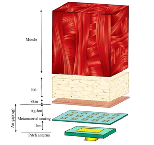 Figure 5: Geometry of the presented metamaterial antenna with body tissue.
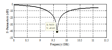 Figure 6: The antenna return losses without the use of metamaterial cover
The value of in Figure 6, refers to the most power being transmitted to the antenna, and that is one of the fundamental definitions in the subjects of antennas. Figure 7 displays the pattern of radiation and the far field in metamaterial-free antenna. As shown in Figure 7, the gain is 7.66 dB at a frequency of 9.6 GHz. Half power beamwidth (HPBW) is the angle between two main beam points, 3-dB below the maximum power. That is 78.9 degrees here, and the main lobe direction is zero. Reducing the HPBW value is our aim for high-frequency applications. Because it indicates a rational directivity for our antenna [1].
3.1. Effect of airspace between antenna and metamaterial
In this section, there is not any gap between the metamaterial coverage and the patch of antenna, and the metamaterial coating including 15 SRR cells printed on a Teflon sheet has been directly mounted on it. In this case, Figure 8 displays the return losses of the antenna, and Figure 9 illustrates the return losses when 10.53 mm of air distance has been applied to the system.
In this situation, frequency has shifted roughly 0.7 GHz than the antenna without metamaterial. The metamaterial coverage is thus positioned at an optimal air gap of 10.53 mm as better results have been derived from the presence of airspace. According to Figure 9, the return loss of the patch antenna is about -50 dB due to the metamaterial coating structure which grants a remarkable performance. Also, the resonance frequency did not change substantially than the base antenna.
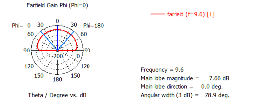 Figure 7: The radiation pattern of the metamaterial-free antenna
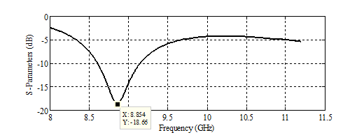 Figure 8: The return losses of antenna without airgap
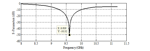 Figure 9: The return losses with airspace of 10.53 mm between the metamaterial and the antenna
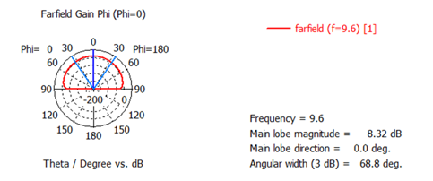 Figure 10: The radiation pattern of the metamaterial-coated antenna
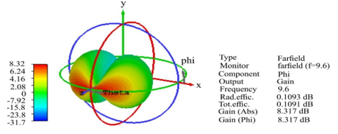 Figure 11: Three-dimensional view of the radiation pattern
Table 2: Comparison of outcomes between antenna without and with metamaterial (MM)
| MM-coated Antenna | MM-free Antenna | Parameters |
| Return losses (dB) | ||
| Gain (dB) | ||
| HPBW (3dB) |
Figure 10 illustrates the antenna radiation pattern with the metamaterial cover. As it can be observed in the Figure 10, the gain obtained is 8.32 dB at the frequency of resonance, the HPBW is 68.8 degrees and the main lobe orientation is zero.
Figure 11 indicates the radiation profile of the metamaterial-coated antenna in view of three dimensions. For comparing and better understanding, antenna outcomes in both types, with and without metamaterial, have been listed in Table 2. The beneficial impact of the usage of metamaterial cover in the function of the antenna is evident, according to Table 2.
As can be seen, gain has improved around 8.6 percent on the microscope patch antenna by supporting this designed structure. HPBW has also significantly decreased by about 12.8 percent. Such angle change has led to a significant improvement in the direction and a better centralization of the main beam of radiation pattern. In most of the high frequency applications, the more the antenna radiation can be transferred in the direction defined and intended or be oriented, the more the antenna would be preferable. Furthermore, in the frequency of resonance the S11 value also has a desirable change in this structure due to the metamaterial antenna configuration and indicates a suitable impedance matching [1].
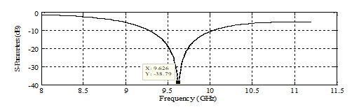 Figure 12: The return losses in the two-layer SRR mode
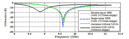 Figure 13: A comparison of the return losses and resonance frequencies of four mentioned antennas
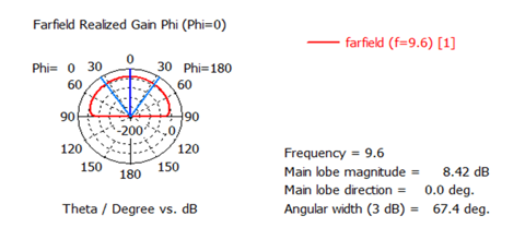 Figure 14: The pattern of radiation in double-layer SRR
3.2. Double-layer SRR effect
The metamaterial cover in this section comprises of two coats of SRR on the lower and upper plane of Teflon.
Because there are 15 SRR unit cells in each Teflon surface, the total number will be 30 unit cells. It has been positioned in the presumed airspace afterwards and outcomes have been compared to the monolayer SRR.
Figures 12 and 14 display the results of return losses and radiation pattern respectively. Also in order to comparing and gaining a better perception of the function of four mentioned types of antennas, results of the return losses have been represented in Figure 13.
The analogy of results between the single-layer SRR and the double-layer SRR can be seen in Table 3.
Table 3: Comparison of modeled SRR values in single-layer mode with double-layer mode
| Two layers of SRR | One layer of SRR | Parameters |
| Return loss (dB) | ||
| Gain (dB) | ||
| HPBW (3dB) |
As shown in Table 3, when the Teflon slab contains two upper and lower SRR layers, although the return loss has reached to -38, it would be in a highly admissible condition nevertheless, and the optimal output of the antenna is not harmed. The gain of antenna has had increasing pattern, plus HPBW has fallen by 1.4 degrees as well. Accordingly, in enhancing the radiation pattern, SRR in double-layer mode could become more efficient style [1]. In the current work, taking into account changes in antenna size and dielectric constant, the metamaterial-free antenna not only had stronger radiation than the compared article patch antenna in [19], but also some modifications in the form and quantity of the SRRs in the metamaterial antenna, as well as the amount of the air gap between the antenna and the cover, allowed noticeable improvements to be made. When we juxtapose the findings of metamaterial antennas in both Tables 1 and 3 (one-layer mode of SRR), we will find that the gain from present work has improved in comparison with the paper described. We decreased the HPBW by around 9.47 percent than the aforementioned article as well. Reducing HPBW implies that the centralization and power of the beam has improved [1]. For most of high-frequency antennas, that would be our key objective.
3.3. Effect of increasing the size and number of SRRs
At this stage, in order to modifying the previous operations, some changes have been applied to the shape, size, and number of unit cells. For this purpose, a piece of copper wire has been added between two squares. Also the number of unit cells has been increased from 5 * 3 unit to 5 * 4, and then to 5 * 5 unit, afterwards results have been investigated. New unit cell is shown in Figure 15. The results for the twenty and twenty-five resonators have been presented in the Table 4.
According to the Table 4, the radiation pattern has improved with the increase of size and number of SRR. But considering the value of S11 and comparing them in both twenty and 25 types, it is observed that as the number of resonators increases, the numerical value of S11 has changed. This means that return losses of antenna in metamaterial coating with 25 resonators have increased. Thus, it can be concluded that the increase in the number of resonators is faced with limitation, and if it exceeds a certain number, the antenna losses will increase.
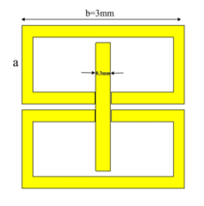 Figure 15: The modified unit cell by adding a piece of wire
Table 4: Comparison of the simulated results between metamaterial with 20 and 25 unit cells
| 5*5
units |
4*5
units |
Number of SRR |
| 9.6576 | 9.6448 | Frequency (GHz) |
| -15.88 | -23.66 | S11 (dB) |
| 9.36 | 8.91 | Gain (dB) |
| 55.9 | 60.2 | HPBW (deg) |
But since in many space applications, antennas with sharp beamwidth are required for detecting and tracing purposes, it seems tempting to use this type of antennas as a lens. For this reason, it is not easy to ignore the sharpened beamwidth and high directivity, that is result of increasing the number of resonators. Therefore, to overcome this limitation, we have benefited a number of circular holes in the ground plane. The procedure is described in section 3.3.1.
- Effect of inserting circular holes in the ground plane
The idea has been derived from the article [22]. The procedure of mentioned paper, has been to improve the antenna radiation pattern by using resonators along with creating nine holes in the ground plane. The use of circular holes, is an old method of limiting surface currents, which reduces the amount of return losses [22]. For this purpose, along with the use of metamaterial coating with 25 resonators, we have created nine circular holes with the radius of 1.5 mm on the ground plane. Figure 16 shows the metamaterial cover, and the holes created on the ground plane.
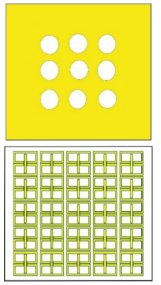 Figure 16: Circular holes created on the ground, and metamaterial coating with 25 unit cells
Table 5: Effect of different radii of holes on the return losses and resonance frequency
| Radius (mm) | Frequency (GHz) | S11 (dB) |
| 0.7 | 9.597 | -15.74 |
| 0.8 | 9.635 | -18.260 |
| 0.9 | 9.638 | -19.94 |
| 1 | 9.635 | -21.71 |
| 1.1 | 9.622 | -24.29 |
| 1.2 | 9.603 | -27.80 |
| 1.3 | 9.568 | -29.24 |
| 1.4 | 9.539 | -42.47 |
| 1.5 | 9.510 | -38.46 |
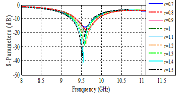 Figure 17: The return losses for different radii of circular holes
It should be noted that the radius of the holes can vary. The results of the effect of several different radii on return losses are presented in Table 5. Figure 17 also shows the return losses for the tabulated amounts derived from CST software.
As it is clear, the return losses have decreased dramatically as the holes’ radii have increased. Frequency fluctuations are slightly visible as well. According to the Table 5, it can be understood that the hole creation significantly reduces the return losses and thus eliminates the antenna constraint caused by the increase of resonators.
It is worth noting that just because the frequency has also shifted slightly with the radius of the hole, in order to increase the accuracy of the radiation pattern results, we have extended the resonance frequency from 9.5 (for hole with radius of 1.5mm) to 9.6, which is the scope of this paper. This object can be easily achieved by altering the substrate dielectric constant from 2.2 to 2.1. For this purpose, we have replaced the Teflon of substrate with dielectric constant of 2.2 to PTFE existed in the software with dielectric constant of 2.1, in which case the frequency has reached 9.68. Also the amount of is about -32 which is quite acceptable.
Figure 18 demonstrates the radiation pattern of the antenna with the final improvement. Table 6 compares the results of this metamaterial antenna with those results in the [22].
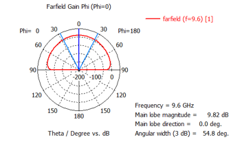 Figure 18: The radiation pattern of antenna including both 25 SRRs and 9 circular holes
Table 6: Comparison of simulated results between final improvement of this paper and paper [22]
| Improvement (measured) | Our work | Reference paper | antenna |
| -4.78 dB | -32.78 | -28 | Return loss(dB) |
| 0.22 dB | 9.82 | 9.6 | Gain(dB) |
| 19.5% | 54.8 | 68 | HPBW(deg) |
The creation of circular holes in the ground plane not only have significantly reduced the return losses, but in comparison with the Table 4 -when there is no hole- they have also increased the amount of antenna gain at a rate of 0.46 dB.
In general terms, the creation of the circular holes along with metamaterials consisting of large-sized and more-numbered resonators have impressively increased the efficiency of the antenna.
This method can therefore be regarded as a solution for reducing antenna losses and overcoming the antenna restriction due to the increase in resonator numbers.
3.4. Effect of Metamaterial layer on the patch antenna in hyperthermia application
Table 7 shows amounts of SAR obtained for different distances of Ag-hm. To better realization of the Table 7, results have been shown in Figure 19.
As it can be seen in the diagram, the lowest amount of output SAR is pertinent to 24 mm, namely maximum Ag-hm distance.
By reducing the distance between the metamaterial coating and the body tissue, the numerical value of SAR has increased relatively, so that at 6.25 mm, the amount of SAR has reached its maximum value of 15 w/kg.
It can be concluded from Table 7 that the distance between the tissue and the metamaterial antenna plays a significant role in the output SAR value. In other words, the SAR values required for different usages can be obtained by varying the distance.
In the next phase of the experiment, the hotspot of the lowest SAR amount obtained (5.2 w/kg), at the maximum distance between tissue and metamaterial, was estimated at approximately 4.8 w/kg. In the following, the rest of the SAR simulations values were normalized accordingly.
A few examples of the results in the normalized SAR value are given in Figure 20.
Table 7: SAR amounts obtained for different distances between metamaterial coating and body tissue
| SAR Amount
(w/kg) |
Air Distance [Ag-hm] (mm) |
| 5.2 | 24 |
| 9.25 | 20 |
| 8.99 | 18.75 |
| 10.1 | 16.66 |
| 10.7 | 15 |
| 11.25 | 12.5 |
| 12.6 | 10 |
| 13.9 | 8.34 |
| 15 | 6.25 |
| 14.5 | 5 |
| 10.1 | 1 |
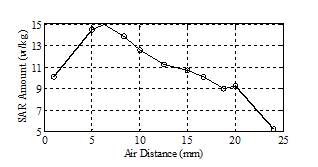 Figure 19: Schematic view of SAR amounts based on different gaps delineated with Table 7 data.
 Figure 20: Normalized SAR based on Minimum SAR (in 4.8 w/kg). (a) Minimum SAR with value of 5.2 w/kg in distance of 24mm. (b) SAR amount: 9.25 w/kg in air gap of 20mm. (c) SAR amount: 8.99 w/kg in air gap of 18.75mm. (d) SAR amount: 10.7 w/kg in air gap of 15mm. (e) SAR amount: 13.9 w/kg in air gap of 8.34mm
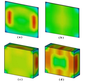 Figure 21: Comparison of heat permeation between usual and MMs antennas in two tissue layers of skin and fat. (a) Skin layer in usual simple antenna. (b) Skin layer in MMs antenna. (c) Fat layer in usual antenna (d) Fat layer in MMs antenna.
As it can be observed in Figure 20, with increasing the amount of output SAR, a larger area of tissue is also involved in heat. Therefore, with altering in this distance we will be able to increase or decrease the amount of the output SAR. To describe precisely, it will be feasible that the amount of heat required come under controlled to some extent.
The use of metamaterial coating on the antenna has another advantage, which is remarkable in its form, and that is the conduction of electromagnetic energy and the heat to the higher depths of the body tissue. This subject causes to reduce damages due to heat in long time to the surface tissues.
Figure 21 shows the two superficial layers of tissue, skin and fat, that compare the amount of transition heat between both types of simple microstrip antennas and metamaterial antennas.
As it is noticeable in Figure 21, in the usual antenna, the first surface layer of tissue namely skin has been burnt and the rest of heat has penetrated to the initial layers of fat, whereas in the metamaterial antenna, heat has penetrated into the deeper layers of fat and there is no burn on the skin tissue.
4. Conclusion
In this study, we took advantage of a type of metamaterial formation as a coating layer upon a microstrip patch antenna with coaxial feeding to upgrade the efficiency of antenna. The proffered small-size antenna was modeled in a resonance frequency of 9.6 GHz, whereby the metamaterial structure layer was used to achieve a highly desirable orientation. The gain of the antenna increased significantly as well, and the half-power beamwidth was decreased by more than 20 degrees than the normal patch antennas, which tend to be striking in spatial tracing applications considering the ordinary quantities of beamwidth in the usual antennas.
Using of metamaterials in antennas not only causes to reduce losses amount, increase the gain and sharpen the radiation as a lens in satellite usages, but also can alter the depth of penetration in medical applications, as well as acquire various SAR amounts, by adjusting the proper distance. In fact, more degrees of freedom will emerge for different applications. Specifically, by using different shapes of unit cells, other forms of these designs will present different outcomes.
- Jahangiri, Mahsa, and Saman Rajebi. “Effect of square srr structure on the radiation pattern of the patch antenna in the x-band.” 2019 5th Conference on Knowledge Based Engineering and Innovation (KBEI). IEEE.
- VESELAGO, Viktor G. The electrodynamics of substances with simultaneously negative values of and μ.. Soviet physics uspekhi, 1968, 10.4: 509.
- PENDRY, John B., et al. Magnetism from conductors and enhanced nonlinear phenomena. IEEE transactions on microwave theory and techniques, 1999, 47.11: 2075-2084.
- SMITH, David R., et al. Composite medium with simultaneously negative permeability and permittivity. Physical review letters, 2000, 84.18: 4184.
- ISLAM, Mohammad Tariqul, et al. A negative index metamaterial-inspired UWB antenna with an integration of complementary SRR and CLS unit cells for microwave imaging sensor applications. Sensors, 2015, 15.5: 11601-11627.
- ENGHETA, Nader. Metamaterials with negative permittivity and permeability: background, salient features, and new trends. In: Microwave Symposium Digest, 2003 IEEE MTT-S International. IEEE, 2003. p. 187-190.
- WITHAYACHUMNANKUL, Withawat; ABBOTT, Derek. Metamaterials in the terahertz regime. IEEE Photonics Journal, 2009, 1.2: 99-118.
- PATEL, B. D.; NARANG, Tanisha; JAIN, Shubhangi. Microstrip Patch Antenna-A Historical Perspective of the Development. In: Conference on Advances in Communication and Control Systems. 2013.
- CONSTANTINE, A. Balanis, et al. Antenna theory: analysis and design. MICROSTRIP ANTENNAS, third edition, John wiley & sons, 2005.
- RAHMAN, Md Mahfuzur. Small size coupling feed and inductive shorting antenna for wide bandwidth, increased gain and efficiency with low specific absorption rate (SAR) operation. 2016. PhD Thesis. Michigan Technological University.
- KARADE, Abha R.; ZADE, P. L. A miniaturized rectangular microstrip patch antenna using SSRR for WLAN applications. In: Communications and Signal Processing (ICCSP), 2015 International Conference on. IEEE, 2015. p. 1002-1004.
- SMITH, D. R., et al. Electromagnetic parameter retrieval from inhomogeneous metamaterials. Physical review E, 2005, 71.3: 036617.
- HOSSAIN, M. I., et al. Low-SAR metamaterial-inspired printed monopole antenna. Applied Physics A, 2017, 123.1: 8.
- ALI, Tanweer; MOHAMMAD, Saadh AW; BIRADAR, Rajashekhar C. A novel metamaterial rectangular CSRR with pass band characteristics at 2.95 and 5.23 GHz. In: Recent Trends in Electronics, Information & Communication Technology (RTEICT), 2017 2nd IEEE International Conference on. IEEE, 2017. p. 256-260.
- Nijhawan, Geeta, Siddharth Sagar Nijhawan, and Minu Sethi. “Hyperthermia Treatments.” Noble Metal-Metal Oxide Hybrid Nanoparticles. Woodhead Publishing, 2019. 241-263
- Mendez, Hector Fabian Guarnizo, Mauricio Andrés Polochè Arango, and John Jairo Pantoja Acosta. “Hyperthermia Study in Breast Cancer Treatment.” Workshop on Engineering Applications. Springer, Cham, 2018.
- Jaffar, Nabilah Abdul, et al. “An overview of metamaterials used in applicators in hyperthermia cancer treatment procedure.” 2017 International Conference on Electrical, Electronics and System Engineering (ICEESE). IEEE, 2017.
- Ebrahimi-Ganjeh, Mohammad Ali, and Amir Reza Attari. “Study of water bolus effect on SAR penetration depth and effective field size for local hyperthermia.” progress in Electromagnetics Research4 (2008): 273-283.
- Paswan, Pradeep, et al. “Performance enhancement of coaxial feed microstrip patch antenna using left-handed metamaterial cover.” 2014 IEEE Students’ Conference on Electrical, Electronics and Computer Science. IEEE, 2014.
- SEO, Je Hyung, et al. Distribution of THz electric field in the split-ring resonator metamaterials based on the thin film geometry. Current Applied Physics, 2016, 16.3: 329-334.
- GARG, Ramesh. Microstrip antenna design handbook. Artech house, 2001.
- Fang, Chao, and Feng Xu. “Performance enhancement of coaxial feed microstrip patch antenna using left-handed material and PBG circular holes.” 2014 IEEE International Conference on Communiction Problem-solving. IEEE, 2014.