Mitigation Methods of Voltage Disturbances and Harmonic Currents of PWM Two-Level Inverter Supplying The 6-Pulse Diode Rectifier

Adv. Sci. Technol. Eng. Syst. J. 5(1), 294–301 (2020);
 DOI: 10.25046/aj050137
In fast charging station for Battery Electric Vehicles (BEVs) the three-phase PWM (Pulse Width Modulation) inverters generate parasitic Differential-Mode Voltages (DMV) and Common-Mode Voltages (CMV). Parasitic voltages are a side effect of using the width modulation to shape the phase-to-phase inverter’s voltage. In this article the authors present a mathematical description of the differential-mode (DM) and common-mode (CM) voltages and carry out their spectral analysis. Based on the spectral harmonics analysis, the authors present a method for filtration of harmonics of DM and CM voltages aimed at limiting the capacitance parasitic currents: due to DM voltage – phase-to-phase parasitic current and CM voltage – ground parasitic currents. A resonant filter was used to eliminate harmonics of the input rectifier of the DC/DC converter supplied from a voltage inverter. As a result of tests, the T HD harmonic content factor was significantly reduced and ground leakage ted from the PE electric shock protection system.
1. Introduction
The DC/DC converter rectifiers for charging electrochemical energy stores used in charging stations of Battery Electric Vehicles (BEV) are non-sinusoidal receivers and generate current harmonics. When PWM inverters are the source of voltage supplying local AC networks, it is necessary to eliminate high-frequency differential harmonics of differential-mode DM voltage and common-mode CM voltage, which are disturbances resulting from the use of PWM modulation. It is also necessary to limit the harmonic content of low rows in the phase current, as they increase losses in the network. In the case of rectifier power supply from the transformer, the phase and thus phase-to-phase voltages are deformed, transformer voltage deformations, determined by the THDu harmonic content ratio, must not exceed of the permissible values [1],[2].
Scientific publications present solutions using transformers to galvanically separate the inverter, which converts the energy of the photovoltaic source from the input rectifier of the AC/DC/DC converter of the EV charger [3]. An interesting solution seems to be the use of a three-winding Yyd transformer in the 12-pulse diode rectifier of the AC/DC/DC charger [4]. One of the authors’ research goals is to demonstrate the possibility of obtaining a level of harmonic content in the inverter current of a value close to when using a 12-pulse rectifier with a Yyd transformer.
This paper consist of theoretical part where the PWM inverter and the 6-pulse diode rectifier are analyses. It also shows the concept of powering from renewable energy sources dedicated for fast charging stations. Next part describes the solution of limiting disturbances of voltage inverters in hybrid system.Thanks to use of novel configuration of filters against voltage disturbances it is possible to mitigate the influence of rectifier on power supply system in charging station. The last part shows the results of simulations of rectifier’s harmonics compensator and laboratory experiments to determine the conditions for cooperation of PWM converter with DC/DC converter using the CM and DM filters.
This article is an extension of the issues presented in the reference [5] and also is a continuation of the research presented there.
2. Hybrid Powering of Power Electronic Converters of EV Charging Station
In order to assure of high power and using of ”clean” electricity, the electric vehicles charging station should be powered from hybrid system with an energy storage. Figure 1 shows an exemplary implementation of a hybrid power supply system for electric vehicles charging station with using the renewable energy sources.
In a hybrid power system a few energy sources is used. The loads are supplying from local AC or DC voltage supply network.
In the hybrid network shown in Figure 1, the local DC voltage line is connected to renewable energy sources (RES) (e.g. wind farms or solar power plants) and energy storages, like batteries, fuel cells or pumped storages. The AC line is powering also DC receivers which are DC fast charging stations for electric vehicles. Solutions are known in which electric vehicles are connected charging station supplies energy to the power grid, here two-way DC/DC converters are used as chargers for electric vehicles EV. The energy of electrochemical batteries can also be sent to an industrial power supply network. At the same time, a power system that is synchronized with the local hybrid power network can complement local sources of ”clean” energy from periods of reduced efficiency (e.g. on cloudy days for solar sources). In periods of increased efficiency of local renewable energy sources, excess energy can improve the efficiency of the power system. In such systems, bidirectional energy converters must be used [5], [6].
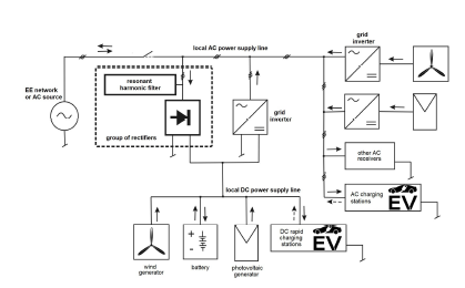 Figure 1: Local hybrid power supply system for EV charging stations with renewable energy sources (wind and PV)
Figure 2 shows the EV fast battery charging station, which is powered from a two-level voltage inverter or from the power grid. The passive parallel harmonic current filter is connected to the AC line with increased current consumption by the diode rectifier. This allows you to control the amount of capacitive reactive power supplied to the AC network by this filter. The passive filter used limits the level of harmonics in the THDi range from 5% to 10% [5]. Powering the EV fast charging station from the low-voltage industrial network leads to distortion of phase and phase-to-phase voltages in this network. Voltage distortions increase due to the power of the battery charging station, in particular at similar capacities of MV / LV transformers in the power system. Such voltage distortions cause disturbances causing incorrect operation of other receivers connected to the power supply network, e.g. contactors, PLC controllers and other [7]. Limiting the current harmonic content is necessary today, because the number of diode rectifiers and their power is constantly increasing.
For the purposes of this article, it was assumed that the MV/LV transformer of the power system supplies, apart from the fast EV battery charging station, also other electric receivers. In places where travelers service on expressways and highways, where fast EV battery charging stations are located, transformers usually power other receivers, such as pumps, lighting, air conditioners. It was assumed that the fast charging station does not have its own dedicated MV/LV transformer, which is why the use of effective limiting harmonics of phase currents is very important.
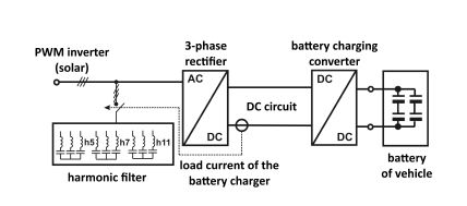 Figure 2: Block diagram of an EV battery charger with a passive harmonic current filter to provide sinusoidal current in the local power supply network
3. Mathematical Description of a Linear Three-Phase Inverter Model
The transformation of DC voltage into single-phase and three-phase AC voltage, with the use of the power-electronic PWM inverter, has side effects such as the CM voltages [8], [9]. In this chapter, the mathematical relations describing the voltage of the common mode disturbances were derived bases on the description of the threephase linear model of the PWM inverter. The three-phase two-level voltage inverter is shown with a symmetrical load in Figure 3. It consists of three identical branches of half-bridges in each phase and this three-phase system is symmetrical for individual harmonics. In modeling and analyzing the inverter, a three-phase notation is used [10], [11].
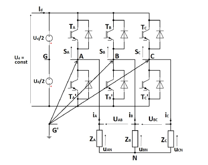 Figure 3: Basic scheme of three-phase two-level inverter with symmetrical load
On the basis of the three-phase inverter description, a mathematical relationship is determined, which describe the CM voltage of the inverter with the grounded negative DC voltage bus and without galvanic ground of the power-electronic elements (such as an industrial inverters and auxiliary railway equipment inverters) [10], [12].
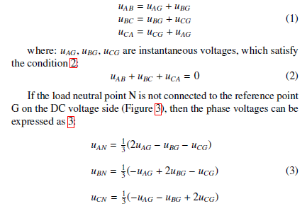
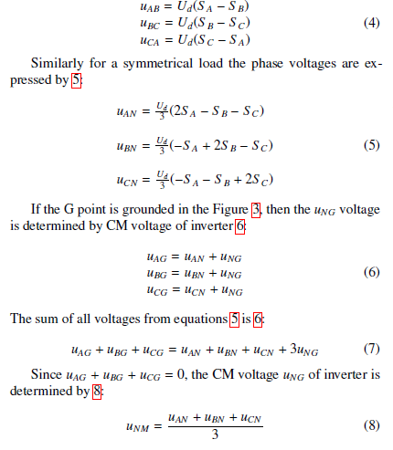
The output phase-to-phase voltages of the inverter are described as follow 1:
 By describing the switching states of inverter S A, S B, SC with 0 and 1 (e.g. S A=1, indicates the state in which the transistor in phase A is switched on, and S A=0, when the lower transistor in phase A is switched off), the output phase-to-phase voltages can be presented as follows 4:
 The relation 8 indicates that the CM voltage of inverter is equal to the voltage with respect to another ground point, e.g. G’ (Figure 3), which is not galvanically connected to the inverter’s electrical circuit (e.g. relative to the protective PE ground of the drive system). However, if the ground potential point G’ is shorted with the negative DC voltage bus, then according to the Figure 3 the voltage uGG0 = Ud/2 and then the following applies 9 [11]:
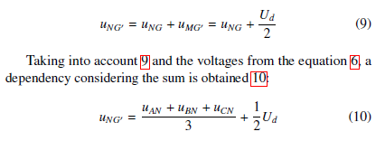 From 10 a conclusion can be drawn that the grounding of the negative DC voltage bus of the inverter does not eliminate the inverter’s common-mode voltage uNG0, but instead only increases its level relative to the ground. The grounding of the negative DC voltage bus of the inverter causes the ground disturbances current caused by this voltage, directly flow into the voltage inverter. It is a property caused a higher impedance in industrial frequency converters, because in this type of inverter’s there is no galvanic connection between the negative DC voltage bus and ground [11].
4. Limiting Disturbances of HighFrequency Voltage Inverters in a Hybrid Grid
The DM and CM voltage of the PWM inverter are its incherent feature [12], [13]. The filtration of these undesired voltages eliminates a number of undesirable phenomena that occur when high-frequency capacitive leakage currents occur: phase-to-phase current from DM voltage and ground current from CM voltage. The use of significant inductance in the DM voltage filter, which simultaneously impedance separates the voltage inverter from the resonant current harmonic filter, simultaneously strengthens the level of current harmonic filtration.
The use of DM and CM voltage filtration is of fundamental importance for limiting the spread of high-frequency disturbances in the hybrid power network [12], [14]. High-frequency ground leakage capacitance currents usually flow through residual current circuit breakers without causing them to respond to an exceeded ground fault current, resulting in a risk of electric shock [15], [16]. Non-sinoidal phase voltages, e.g. in the form of a symmetrical rectangular waveform, will always generate a CM rectangular voltage. Rectangular phase voltage with phase shifts close to zero arise with the sinusoidal PWM modulation of the inverter and the modulation depth factor M is close to zero.
In the inverter model from 5 supplying the diode rectifier from Figure 10, a parallel resonance filter was used to limit harmonics in phase currents. Inductance (L3, L4, L5) of the DM voltage filter increases the impedance between the inverter and the resonant current filter, thereby increasing its efficiency [5], [13].
Suppression of the CM voltage harmonics of the PWM inverter is possible by forcing the capacitive leakage current CM as shown in Figure 5. When the AM1 ammeter current is zero, only the harmonics of the DM voltage are suppressed and the inverter phase-to-phase voltages are sinusoidal.
When the i0 = AM1 current is different from zero then additionally the phase voltages are also sinusoidal and the CM voltage can be described by the formula 11:
 where: i0 = current at AM1, Cf – filter phase capacitance (Figure 5: C6, C7, C8 and if C5 Cf the uCM = uC5).
Formula 11 shows that with sufficiently large phase capacities
Cf of the DM voltage filter it is possible to obtain phase voltages in the form of pure sinusoidal waveforms. The voltages obtained from the inverter (e.g. photovoltaic) supply the premises with a threephase AC voltage line to which single- and three-phase receivers can be connected. Therefore it should be free of harmonics deforming phase voltages. In the present case, the AC line is loaded with the diode rectifier of the EV battery charger (Figure 10). The rectifier battery load models the load while charging the battery storage (e.g. DC/DC loaded converter). When galvanic connection of the inverter power outputs with the rectifier power inputs, a sufficiently large inductance value in the current path must be ensured. In the simulation tests, the inverter sinusoidal PWM modulation with a carrier frequency of 6kHz is used (modulation depth factor M = 1).
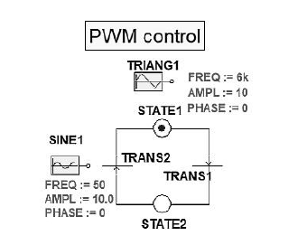 Figure 4: Event graph for PWM control of a three-phase inverter for one phase
The inverter PWM control in the form of an event graph is shown in the Figure 4. The carrier section is a symmetrical triangle with a frequency of 6kHz. Modulating waveforms are 50 Hz sine waves. In each phase they are phase shifted by an angle of 120◦. For conducted tests of current harmonics produced in the rectifier and CM and DM inverter voltages, sinusoidal PWM modulation is used.
In the inactive phase of the inverter (i.e. when energy is not supplied by the inverter), the energy accumulated in the current path inductances maintains a sufficiently large rectifier supply current. The LC inductance of the DM disturbance filter accumulates energy (WL=0.5LI2), which supports the flow of phase currents to the rectifier when PWM modulation blocks the flow of currents through the inverter IGBTs.
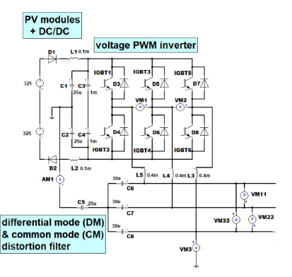 Figure 5: Two-level PWM inverter with DM and CM voltages filters with local AC line to supply of diode EV charger rectifier
The model of inverter with PWM sinusoidal modulation to feed diode rectifier in electric vehicles charging station is shown in the Figure 5. The reference [17] proposes other system structure with use the isolation transformer or boost converter [18] with inverter [1]. The inverter is powered by a solar power plant using PV modules (solar energy). The inherent DM and CM voltages of the PWM inverter are minimized with the DM filter (phase-to-phase harmonics) and CM filter (phase voltage harmonics after filtering the DM harmonics first) [6].
The PWM inverter model with DM and CM voltage filters used in simulation tests is shown in Figure 5. It enables simulation tests of the hybrid power system [5]. Ansys Simplorer software was used to build the model and perform simulation tests.
The phase-to-phase waveforms of the inverter obtained in simulation tests indicate that the parallel resonant harmonic filter in phase currents strengthens the inverter’s DM voltage filtration efficiency. Comparing the phase-to-phase voltages of the inverter shown in Figures 6 and 7, a nearly 10% reduction in the THDu harmonic content factor is visible when the current harmonic filter is on.
The voltmeters VM1 and VM11 used in the voltage inverter model from Figure 5 indicate the phase-to-phase voltages before and after the DM voltage filter, respectively. Figure 6 shows voltages when switched off and figure 7 when the resonant current harmonic filter is switched on.
Occurring surges in the phase-to-phase voltage lead to numerous undesirable phenomena, including resonance phenomena. Suppression of higher harmonics at phase-to-phase voltage is fundamental when limiting the high frequency disturbances spread in the local AC network. The beneficial effect of the applied harmonic phase current filter on increasing the harmonic suppression of the DM voltage in the phase-to-phase voltages of the inverter is shown in Figure 7.
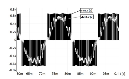 Figure 6: Phase-to-phase voltage of loaded PWM inverter (VM1) before DM and CM filters and after DM and CM filters (VM11 – THD1u=17.55%) when resonance harmonic filter is off
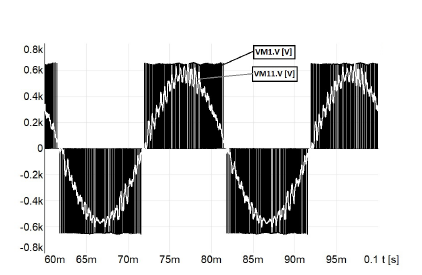 Figure 7: Phase-to-phase voltage of of loaded PWM inverter (VM1) before DM and CM filters and after DM and CM filters (VM11 – THD1u=7.65%) when resonance harmonic filter is on
5. Model and Research of a Current Resonant Filter in a Three Phase Rectifier System Powered by a Voltage Inverter
Fast EV charging stations can be DC or AC powered. DC supply from renewable energy generators or electrochemical reservoirs (e.g. lithium-ion storage) relieves the local AC network. Power supply for the input rectifiers of EV battery chargers (DC/DC converters) requires harmonic current filtering, e.g. by using 5, 7 and 11 harmonic passive parallel filters. The harmonic filter is attached to a three-phase AC line depending on the rectifier’s current rating. At low current diode rectifiers, the filter is disconnected from the
AC line to limit the reactive capacitive power supplied to the power system (Figure 2).
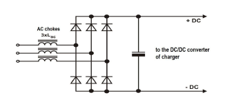 Figure 8: Chokes at the diode rectifier inputs to limit the steepness of the capacitor bank charging current pulses – AC chokes
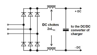 Figure 9: Chokes on the DC voltage side of the diode rectifier to limit the steepness of the current pulses of the capacitor bank charging – DC chokes
Three-phase diode rectifiers are equipped with AC chokes – Figure 8 or DC – Figure 9, or a combination thereof. These are usually chokes that cause a phase voltage drop from 3% to 4% at nominal current, which results in providing THDi harmonic content ratio below 45% [1]. AC chokes protect the AC line against switching commutation of current in rectifying diodes, but they cause undesirable reduction of the rectified voltage value. DC chokes do not lower the straightened tension. If the source of AC voltage supplying the rectifier in the hybrid power supply network is a voltage inverter, then when determining the value of the AC or DC choke inductance of the rectifier, the inductance of the inverter’s DM voltage filter should be taken into account. Usually the AC and DC chokes have similar inductance values, which decrease proportionally with increasing power of the rectifiers [5]. DC reactors are placed symmetrically in the branches +UDC and –UDC to ensure a symmetrical CM voltage of the rectifier relative to the ground potential, when it is fed from a power network with a TN network system.
The values of the capacity of the batteries and chokes used in the diode rectifiers for 50kW and 500kW EV converters are summarized in Table 1. The proportional relationship between the capacity of the EV rectifier batteries (figures 8 and 9) and its power is visible here, and the inductance of the chokes is inversely proportional.
Table 1: Basic parameters of EV rectifiers with power 50kW and 500kW
| Pr[kW] | 50 | 500 |
| CDC[mF] | 10 | 100 |
| L0(4%) = LDC[mH] = LAC[mH] | 0.3 | 0.03 |
Using the L0 AC or DC chokes in the rectifier with a CDC capacitor battery EV charger with values from the table 1 reduces the harmonic content THDi in the phase current of the AC line to a value of approx. 40%-45% [1]. Further reduction of the harmonic content coefficient, to the level of nearly 12% (Figure 12), was obtained by using a three-branch passive resonance filter (for 5th, 7th, and 11th harmonic). Obtaining phase sinusoidal currents increases the efficiency of the EV charger rectifier supply system [6]. The AC and DC inductance of the chokes presented in table 1 take into account the inverter DM voltage filter phase inductance connected in series or the transformer inductance when the EV charger is powering from the power grid.
6. Model and Simulation Tests of The Rectifier’s Harmonic Current Passive Filter
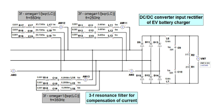 Figure 10: Model of 6-diode rectifier with parallel resonant filters for 5th, 7th and 11th harmonics
Diode rectifiers are commonly used to convert AC voltage to DC. In the DC/DC converter, the voltage is processed in such a way as to maintain a constant allowable current for charging the EV battery (Figure 1). In the rectifier model shown in Figure 10, the individual components mean: bank of capacitors (C9, C10), rectifier resistance load (R1 + R2), harmonic resonant filters for 5th, 7th and 11th harmonics.
Fast Fourier transform was used to set the coefficient of the THDi phase harmonics. The results of simulation tests are shown in Figures 11 and 12.
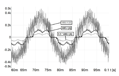 Figure 11: Phase voltage and currents waveforms on AC local network with the PWM inverter and diode rectifie: VM3 – phase voltage before rectifier, AM2 (THDi=45,4%) current before the harmonic filter, AM3 – current after the harmonic filter when filter is off (Figure 10)
The phase current harmonics in Figures 11 and 12 are effectively filtered by means of a passive resonant filter. The high efficiency of the resonant filter is obtained by using the inductance of the inverter’s DM voltage filter (Figure 5). In simulation studies, effective harmonic filtration has been demonstrated in the power supply system of a voltage inverter – diode rectifier, without the use of a separating transformer between these converters.
Figures 11 and 12 also show the VM3 phase voltage of PWM inverter loaded with active power of 50kW. The sinusoidal shape of the VM3 phase voltage indicates the effective operation of the CM voltage filter on PWM inverter outputs (Figure 5).
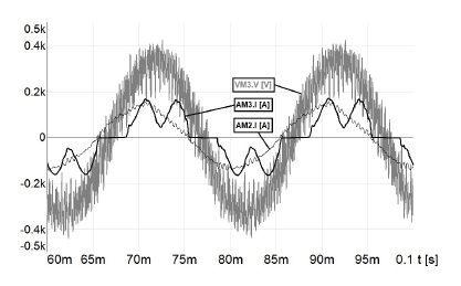 Figure 12: Phase voltage and currents waveforms on AC local network with the PWM inverter and diode rectifier: VM3 – phase voltage before rectifier, AM2 – current before the harmonic filter, AM3 (THDi=12.21%) – current after the harmonic filter when filter is on (Figure 10)
7. Laboratory Experiments Results
Laboratory stand to testing cooperation of PWM volatge inverter
(1) with rectifier (7) of drive inverter loaded with motor (11) is presented on the Figure 13.
The stand was built to examine the cooperation between a voltage inverter (for example, as a voltage source of a photovoltaic power plant) and a diode rectifier loaded with capacitive battery (for example, as an input stage of the DC/DC converter of an electrochemical energy storage charger). This solution does not use a separating transformer between the inverter and the rectifier, because it is an expensive solution, with large dimensions and weight. The authors are looking for an alternative (low cost) solution without using transformer separation between the inverter and the rectifier.
The main purpose of the research is to determine the conditions for cooperation of a PWM voltage converter generating three-phase alternating voltage with a DC/DC converter for charging EV batteries as shown in the Figure 1.
The laboratory stand, depicted on the Figure 13, for AC nominal line currents 3x10A/50Hz and phase-phase voltages 3x400V/50Hz contains:
- LC filter (3xL=4mH, 3xC=3µF) at the inverter output
(differential-mode voltage filter) (4), which limits high frequency disturbances in phase-phase voltages of inverter (1),
- radio frequency interferences filter RFI (2) of the inverter (1),
- branch of CM voltage filter: 2xC=2×15µF, L=1mH (5),(6),
- diode rectifer of the voltage inverter (7),
- excess energy dissipation resistor (8),
- load system (11),(12) of the voltage inverter (7).
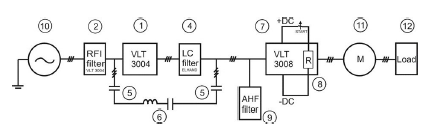 Figure 13: Block diagram of the laboratory stand for testing the cooperation of the renewable energy voltage inverter with the diode rectifier of the vehicle battery charging system
Figure 14 shows the measured line current and phase voltage on the power supply of the loaded diode rectifier of AC/DC/AC converter with 10A current. A significant deformation of the line current in the measured phase is visible as a result of charging the rectifer’s (AC/DC converter) capacitor banks (THDi approx. 45%).
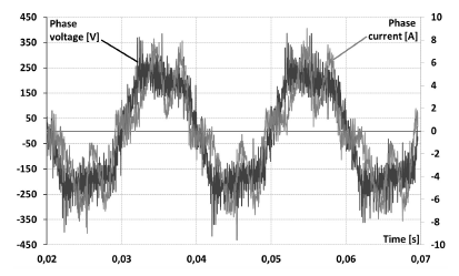 Figure 14: Phase voltage and phase current after the LC filter (4) at the test stand shown in the Figure 13 with the passive harmonic filter AHF [order: 5, 7, 11] switched off (9)
The phase voltage has a limited harmonic content of high orders, which confirms the correct operation of the CM filter (Figure 13). Previous simulation tests of the model of the local power supply system for vehicle battery charging stations are consistent with the experimental results (Figure 11) The capacitive reactive power consumption is not significant here,which results from a negligible phase shift of the first harmonic of the current and phase voltage.
The increased consumption of capacitive reactive power is observed after connecting the AHF passive harmonic filter (orders: 5, 7, 11), also under nominal load conditions, as shown in the oscillogram from the Figure 15 and the values are cosφ1=0.89, φ1=27◦.
The oscillogram from the Figure 15 confirms the effective filtration of low order harmonics through the attached parallel resonant hamonic filter. The high efficiency of the LC passive filter was obtained by using nearly 3% current path inductance (i.e. 3% phase voltage drop on the inductance at nominal current), such as rectifier DC inductance (Figure 9) and DM disturbance filter inductance (Figure 5). Oscillogram from the Figure 15 also shows that the use of a resonant parallel harmonic filter has enabled the reduction of phase current harmonics to THDi = 12.2% from above 45%. The experimental result confirmed the previously obtained simulation test result of the model shown in the Figure 12.
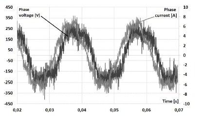 Figure 15: Phase voltage and phase current after the LC filter (4) at the test stand shown in the Figure 13 with the AHF passive harmonic filter [order: 5, 7, 11] switched on (9)
8. Conclusions
The presented system from transformerless supply of a 6-diode rectifier from a two-level PWM inverter is a low cost alternative to supplying the rectifier using a transformer. The tested power supply system can be used in fast EV charging stations. The system enables building a scalable EV charging station composed of modules, e.g. 50kW each.
In the tested system, the current efficiency of the inverter is comparable to the load power of the rectifier.
The applied CM and DM voltage filtering of the inverter made it possible to obtain practically sinusoidal phase and phase-to-phase voltages in the local three-phase AC network.
By using a passive resonant current harmonic filter, practically sinusoidal phase currents in the AC network were obtained at high loads of the diode rectifier, which increases the efficiency of the tested power supply system.
The applied DM differential voltage filters and CM common voltage provide a sinusoidal shape of phase and phase-to-phase voltage in the three-phase local AC network. The inductance of the 3xL DM filter also allows the accumulation of energy necessary to maintain the rectifier current continuity. In the inactive phase of the inverter (operation with passive control vectors: 000 or 111), the energy accumulated in the DM filter inductances is transferred to the rectifier.
To obtain sinusoidal phase and phase-to-phase voltages in the local hybrid three-phase voltage network, it is necessary to use DM and CM voltage filters of the inverter. The inductance of the DM voltage filter enhances the efficiency of the resonant harmonic filter of phase currents. If the CM filter is using, an additional energy storage to limit the voltage rise above the permissible value in the inverter’s DC circuit is need to consider. In case the PWM voltage inverters feed the rectifier circuits, it is necessary to use passive or active harmonic filter. The use of a passive harmonic current filter between the inverter and the rectifier has made it possible to reduce the THDi of phase currents to a level similar to that of 12-pulse rectifiers with a transformer.
Simulation and experimental tests performed of the hybrid network model using the PWM inverter, filters and the rectifier showed the possibility of obtaining three-phase voltage source of PWM inverters with limited harmonic content.
Conflict of Interest
The authors declare no conflict of interest.
Acknowledgments
In the part of the article related to the modelling of the electric circuit, the ANSYS Software national scientific software license has been used, which was funded by a computational grant obtained by Kazimierz Pulaski University of Technology and Humanities in Radom, Poland.
- Hansen S., Asiminoaei L., Blaabjerg F., Simple and Advanced Methods for Calculating Six-Pulse Diode Rectifier Line-Side Harmonics, 38th IAS Annual Meeting. Conference Record of the Industry Applications, vol. 3, 2003, pp. 2056 – 2062, DOI:10.1109/IAS.2003.1257849.
- Szymanski J., Common and differential mode voltage in frequency conventer drive systems. ElektroInfo, vol. 11, 2013. (article in Polish with an abstract in English).
- Li X., Xing X., Zhang Ch., Chen A., Qin Ch., Zhang G., Simultaneous Common-Mode Resonance Circulating Current and Leakage Current Sup- pression for Transformerless Three-Level T-Type PV Inverter System, IEEE Transactions on Industrial Electronics, Volume: 66 , Issue: 6 , June 2019, DOI: 10.1109/TIE.2018.2860555.
- Trivedi N., Gujar N., Sarkar S., Pundir S.P.S., Different fast charging methods and topologies for EV charging, 2018 IEEMA Engineer Infinite Conference,
DOI: 10.1109/ETECHNXT.2018.8385313 - Szymanski J., Zurek-Mortka M., Harmonic Resonant Filters of Quick Battery Charging Station of Motor Vehicles, 23rd International Conference Electronics,
IEEE, 2019, DOI: 10.1109/ELECTRONICS.2019.8765691 - Zurek-Mortka M., Szymanski J.: Reactive power compensation in a harmonic environment. elektro.info, vol. 10, 2018. (article in Polish with an abstract in English).
- Pedzisz K. Capacitor banks measuring analysis and operating condition assess- ment in industrial environment, Journal Electrical engineering and electronics, vol. 27, p.2, 2008.
- Kempski A., Smolen´ski R., Decomposition of EMI Noise Into Common and Directional Modes in PWM Inverter Drive System. Electrical Power Quality and Utilization, 12 (no. 1), 2006.
- Pairodamonchai P., Sangwongwanich S., Exact Common-Mode And Directional-Mode Equivalent Circuits of In-verters in Motor Drive Systems Taking Into Account Input Rectifiers. IEEE PEDS’11, Singapore, 5-8 Decem- ber, 2011.
- Ambroziˇ c, V., Zajec P., Elektri ˇ cni, Servo Pogoni, Slovensko zdru ˇ zenje elek- troenergetikov CIGRE-CIRED, Ljubljana 2016.
- Szymanski J., The Voltage of Common-Mode Disturbances in Frequency Con- verters in Railway Systems. Monography, UTH Radom, 2015.
- Tallam R. M., Skibinski G. L., Shudarek T. A., Lukaszewski R. A. Common- mode voltage reduction PWM algorithm for AC Drives, IEEE Transac- tions on Industry Applications, vol. 46, no. 5, pp. 1959–1969, 2010. DOI: 10.1109/TIA.2010.2057396.
- Takahashi S., Ogasawara S., Takemoto M., Orikawa K., Tamate M., Common- Mode Voltage Attenuation of an Active Common-Mode Filter in a Motor Drive System Fed by a PWM Inverter, IEEE Transactions on Industry Applications, pp.1-1, 2019. DOI: 10.1109/ICEMS.2017.8056376.
- Danfoss, Output filters design guide – MG90N402, 2010.
- Czapp S. Operation of residual current devices at an increased frequency of differential current. ElektroInfo, vol.10, 2008. (article in Polish with an abstract in English).
- Charoy A., Dunand Ph., Bearing currents induced by a power drive. Automotive Power Electronics, 26 – 27 Sept., Paris, pp.1-7, 2007.
- Park J.K., Kim Y.H., Jung Y.Ch., Won Ch.Y., A novel control strategy of an active clamped flyback inverter with synchronous rectifier for a photovoltaic AC module system, 8th International Conference on Power Electronics – ECCE Asia, 2011. DOI: 10.1109/ICPE.2011.5944557.
- Genikomaskis K.N., Gutierrez I.A., Thomas D., Ioakimidis C.S., Simulation and design of fast-charging infrastructure for a university-based e-Carshring System, IEEE Transactions of Intelligent Transportation Systems, vol.19, no.9, 2018. pp. 2923–2932. DOI: 10.1109/TITS.2017.2767779
No related articles were found.