Constrained Path Planning for Both Smooth Motion Profile and Stable Control

Adv. Sci. Technol. Eng. Syst. J. 5(1), 93–99 (2020);
 DOI: 10.25046/aj050112
In our era, human and machine must share the same workspace in various plants such as warehouse logistics, material transportation, manufacturing factory or assisted human. The collaboration is essential to maintain the safe operation and the complete mission. In this paper, a design of anti-vibration scheme using Spline generator for grounded vehicle platform in human-machine interaction is introduced. This hardware structure is able to play a role as carrier in loading application or human assistant in real life. In most of cases, vehicle must convey cargo from start point to destination instead of human while its reference trajectory conflicts with human’s movement. The proposed algorithm helps to carry out a decision of stopping strategy with the least vibration as possible to avoid accident. From the test results, the proposed design is feasible and capable to apply in numerous industries.
1. Introduction
In the first and second industrial revolution, human labor is the main factor to build the products in the workshops, factories, or warehouses. The productivity of this stage mostly depends on the human factor such as clock operation, time off, overtime, short-term payment. Until 1950s, the Automated Guided Vehicle (AGV) was firstly introduced as an advanced mobile robot which uses wires, UV marks and light to navigate. Nowadays, AGVs are even more advanced by using magnets, laser range finder or digital cameras to pilot. Moreover, the most complex guidance technique is currently an integrated on-board with sensors and software, using wireless or radio frequency connection for routing. This autonomous system is commonly applied in large scale factories and storehouses to transport materials from one place to another or assist human by following them with packages. AGVs come with powerful computers that are connected to the cameras, lasers and sensors. This allows vehicle to handle multi-tasking or complex missions all the time. It is completely safe to walk or stand around AGVs while they are operating. On the other hand, unlike human, AGVs can work overtime and will result in the growth of productivity and minimize the expenses.
However, in most of the autonomous system, while they are working, there are always exist residual vibration, which leads to the lack of accuracy. For instance, the crane with heavy load in the end-effector is moving from one place to another. And when it’s stopped, the vibration occurs proportionally to the mass of the load, which not only lead to the inaccuracy but also damage the joints of the crane. In other example, the AGV is following human with a bulky material above and still maintain the safe distance to human. It is assumed that sudden collision would force AGV to stop immediately. If it is not stopped properly, the materials above would collapse due to the vibration. In [1, 2], the researchers composed of four major functional blocks including human detection and human feature, dynamic social zone, approaching pose of the robot to a human or a human group. They are incorporated into a motion planning system, comprising a local path planner and dynamic window technique. The output of research is only focus on driving a mobile robot to approach both stationary and moving humans in a socially acceptable manner. They did not concern on dynamic constraints of system model to guarantee the safe operation. In the applications where the oscillating dynamics is not easily detectable with the standard sensors that hung on the plant, accordingly, it cannot be compensated by a feedback control action. The use of a feed-forward control is often the only option for reducing the vibrations. this technique [3-5] is very effective in vibration suppression, but it may be not useful in trajectory following application such as 3D printing, cutting … The alternative method to dominate oscillation is the use of finite impulse response filter for planning minimum-time trajectories [6, 7] was presented. This investigation connects between analytic functions and dynamic filters permit a generalization of various trajectories. It is usually obtained by second- or third-order polynomial functions to a generic order with only a modest increase of the complexity. The exponential jerk along with filters was investigated as a new type of trajectory [8, 9]. As a matter of fact, constant jerk trajectories did not guarantee a complete vibration suppression when the damping of the resonant modes is not negligible. The decay rate and duration of the jerk impulses that allow residual vibration cancellation are derived in an analytical way as a function of the dynamic characteristics of the plant. Some comparisons with the well-known input shaping techniques combining with filters performs the advantages of this method. In [10-12], the authors demonstrated the theories of motion profiles from basic to advance, the mechanism of motion generators and their applications in industry. They acquainted with polynomial profile, exponential profile and multi-segmented profile to figure out the generation of robot trajectory. One of advanced path generators is a uniform B-splines of degree p. The investigators in [13-15] developed the spline trajectories with a chained composed by p average filters to optimize. It could find out the solutions for two different troubles such that exactly interpolating a set of given points by means of a complex trajectory and the need of suppressing mechanical vibrations. However, these researches are only simulated in virtual environment from theories. It needs more time to overcome practical problems, for example, time consuming to generate motion profile, burden computation in computer or high cost comparing to other methods.
In this paper, the exponential B-spline trajectories are taken into consideration and able to generate exactly if the profiling parameters are chosen properly. Besides, for safety in the working environment, there are many options such as stereo cameras, laser sensors, proximity sensors that could be placed additionally. A Kinect camera is chosen because of its advantages, i.e. cheap price, easy to calibrate, library supported and most importantly human detectable. A Kinect camera is attached on the vehicle to calculate the distances when humans are detected while moving along its path, based on the depth sensor integrated in the camera. The experimental results performed on an automatic guided vehicle, show the effectiveness of the proposed method.
2. B-spline and Applications
Splines are piecewise polynomial functions widely used to interpolate sets of data points or to approximate functions, curves and surfaces. The data may be either one-dimensional or multi-dimensional. A spline of order is a piecewise polynomial function of degree in a variable of . The values of where the pieces of polynomial meet are known as knots, denoted and sorted into non-decreasing order. When the knots are distinct, the first derivatives of the polynomial pieces are continuous across each knot. When knots are coincident, only derivatives of the spline are continuous across that knot.
2.1. B-spline Functions
A particularly efficient technique for the computation of splines is based on so called B-splines, or Basic-splines. The reason for such a name is that a generic spline can be obtained as a linear combination of a proper number of B-spline basis functions, , i.e.
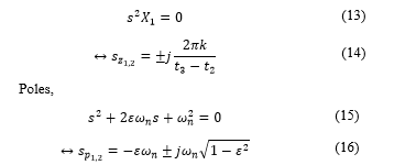
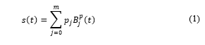 where
where
is the curve trajectory.
are the control points.
is the B-spline basis function of degree .
is the knot vector.
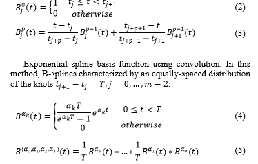
B-spline basis function can be generated by using Cox-de Boor formula or convolution method. B-spline is a general term.
where
is a cubic polynomial spline.
is an exponential spline of degree 3.
is an exponential tension spline of degree 3.
is an exponential general spline form produces B-splines that are a linear combination of function .
Cubic polynomial spline can be generated in both methods. Exponential spline can only be generated by using convolution method.
Cubic polynomial spline basis function using Cox-de Boor. In this method, B-splines are piecewise polynomial, characterized by a knot vector . The relation between knots, and number of control points, is
 2.2. B-spline Applications
The linear combination of B-spline basis functions with a set of control points can solve the interpolation problem, therefore, in mathematical subfield of numerical analysis, it is widely used for curve fitting and numerical differentiation of experimental data. In computer-aided design and computer graphic, B-spline basis functions are used for generating and representing curves or surfaces.
3. Motion Planner Using B-Spline
Smoothness, flexibility and possibility of exactly interpolating some via-points are the main characteristics of B-spline functions. Therefore, we believe that it is possible to generate B-spline trajectories which exactly cross the desired via-points and at the same time are able to suppress vibrations.
3.1. B-spline Curve Generator
Using Cox-de Boor formula, it can only solve the cubic polynomial spline case. Though, it’s a practical method to generate the B-spline trajectory for autonomous system while maintaining the properties of system. The proposed algorithm of flexible and controllable motion generator is illustrated in Fig. 1. In this case, the B-spline curve has degree 3 together with its control polygon defined by.
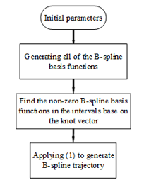 Figure 1. Proposed algorithm of B-spline trajectory generator.
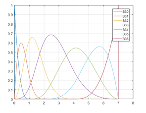 Figure 2. B-spline basis functions using Cox-de Boor formula
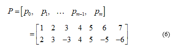
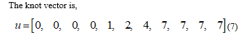
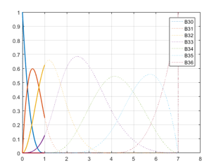 Figure 3. Non-zero B-spline basis functions in the interval .
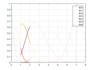 Figure 4. Non-zero B-spline basis functions in the interval .
To generate the B-spline with above parameters, a method of path planning using various basis functions has been investigated. According to Fig. 1, with the initial parameters (the control point vector and the knot vector) and a combination with (3), it is able to generate the B-spline basis functions, note that the variable in (3) now becomes in (7) with with respect to the example. Since it has a total of seven control points, it requires seven B-spline basis functions of degree 3 which are to be able to calculate the trajectory using (1). After calculating all of the B-spline basis functions, note that in every knot span , there are at most basis functions are not null, namely , for example there are 4 basis functions are not null in the interval as shown in Fig. 5. Using (1), for each of the B-spline basis functions of degree 3 as mentioned above, multiply it with the corresponding control points, as a result we have , which is a vector with the first row stands for the time in the x-axis and second row stands for the amplitude of the trajectory in the y-axis.
Fig. 2 introduces all of the B-spline basis functions in the interval . Note that, at every sampling time, the sum of all of the B-spline basis functions at that time is always equal to 1, this is also one of the characteristics of the B-spline basis functions.
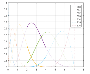 Figure 5. Non-zero B-spline basis functions in the interval .
In Fig. 3 and Fig. 4, there are 4 non-zero basis functions which are available in the interval and , they are and respectively.
Similarly, in Fig. 5 and Fig. 6, there are 4 non-zero basis functions which are available in the interval and , they are and correspondingly. By integrating these basis functions, the result of B-spline could be achieved in equation (1). For the convolution method, the above steps are applied to generate the B-spline trajectory. This method can generate not only cubic polynomial spline but also the exponential splines. The path planning of cubic polynomial shape is described in Fig. 7. A series of points where the amplitude of the trajectory in the vector locates in y-axis and the time in the vector places in x-axis are connected to form a desired trajectory.
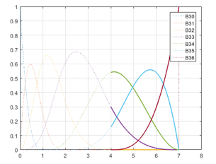 Figure 6. Non-zero B-spline basis functions in the interval .
3.2. Smooth Profiling Generation
In order to prove the effectiveness and correctness of B-spline application for vibration-less motion, a practical example of material transportation in factory has been chosen. An automated guided vehicle (AGV) with cargo must travel in long distance during working hours. It is recognized that the stable movement is difficult to gain since the vibration occurs. To conquer these troubles, we apply B-spline trajectory to reduce the oscillation. Fig. 10 illustrates the system modeling of both AGV and cargo as m1 and m2. They are linked together via a string (stiffness k) and damper (viscous coefficient b).
: inertial force acting on m2
: velocity of m1
: displacement of m1 and m2
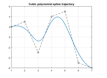 Figure 7. Cubic polynomial spline trajectory.
Figure 8. Modeling of both vehicle and cargo.
Using Newton law, we have equation of system dynamics in time domain
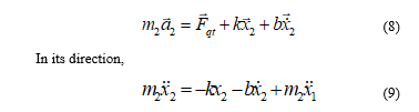
By applying Laplace transformation, the below description is in frequency domain
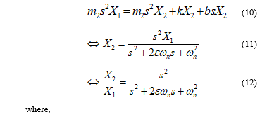 where,
: the natural frequency of the of the lightly damped system.
: the damping ratio.
From equation (11), it has been known that the system vibrates more at pole points while it maintains a stable state at zero points are the points. On the other hand, the system is stable if the poles lay on the left side of the complex plane or being replaced by the zeros using the pole placement technique. In (12), we can find the zeros and poles of the system.
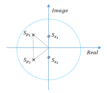 Figure 9. Poles and Zeros in the complex plane.
Zeros,
 The zero points together with pole points are illustrated in the complex plane as Fig. 9 below.
4. Planning the Proposed Scheme
In the present work, we discover the case of automated vehicle which lifting cargo to transport material in factory. The test scenario was set up as Fig. 10 which the proposed scheme is experimented on a model of vehicle. It is attached the flexible beam together with mass and an accelerometer above. In front of vehicle, one digital camera is hung on anterior cover. The distance to conflict with objects could be estimated since it returns all coordinates in workspace. The test surrounding is internal area of textile factory where there are a lot of workers. As a result, the potential accident between human and machine could happen at any time. The proposed scheme is able to overcome these troubles perfectly.
In detail, the automated guided vehicle is driven by using a TI’s board to output PWM signal. A powerful DC driver that is capable to protect the over current or isolate the reverse current, is motivated to control DC motor. The accelerometer is a Sensors Booster-Pack, manufactured by Texas Instrument and include several sensors into one pack. We utilize this sensing module to recognize the magnitude of oscillation in respect to time. This sensor would direct data back to host server through UART protocol. Whenever the mobile vehicle moves, with mass, the oscillation occurs to act on aluminum beam. The swinging of beam is recorded by sensing module. Later, oscillating data is transmitted to host personal computer. Moreover, a Kinect camera locating ahead of robot, has fully functional image processing techniques. We program an interface software with camera in C/C++ language.
Theoretically speaking, it is desired that there exists an effective and feasible method to reduce the residual vibration in such situation. To verify our approach, the polynomial cubic spine, exponential spline of degree 3, exponential tension spline of degree 3 and exponential general spline scheme are recommended to achieve free-vibration motion. The geometric trajectory is collected via linear lines with circular lines in a sequence of equally segment due to control points pi. Once, the flexible curves are generated to evaluate the exactly tracking ability of system and stable response. However, owing to residual vibration, the actual performance differs with command curvatures of the bends. For such fluctuation, it is traditionally considered that robot’s direction movement along with y-axis would produce the residual vibration concerned on x-axis response. The higher velocity the autonomous robot reaches to, the larger amplitude of oscillation takes place.
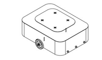 Figure 10. Simulation model of autonomous vehicle.
Based on proposed approach, an experimental prototype of potential collision has been built as Fig. 11. The differential drive mechanism depending on dissimilar speeds, orientates itself to turn left or right.
5. Discussion
The path planner based on cubic spline curve is denoted as Fig. 12. A series of B-spline basis functions are synthesized to perform the flexible and bended trajectory. Nevertheless, at each sampling time, there is only one basic function that is the most weighted scheme. Also, the determination of basic functions depends on control way-points. As we expect, the routing passes through all the given way-points.
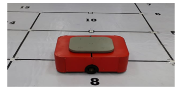 Figure 11. Practical model of autonomous vehicle.
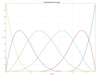 Figure 12. Cubic spline trajectory generation.
Note that there is a unique synthetization of control points which meets the way-point constraints. It could offer more degrees of freedom by swelling the number of control points. To utilize this generation more effective and real-time cost, a powerful CPU needs to be explored. The B-spline based motion profile of mobile vehicle is achieved as Fig. 13. The motion generator outputs driving command owing to interpolation functions. It provides an exact characterization of such category of routing line. While moving with feasible profile, the autonomous robot could ensure to reach desired parameters such position, speed, acceleration and jerk. To measure the impact of proposed approach, the reaction of mass m2 is recorded in Fig. 14. The variation of m2 tends to zero when time is infinite. From these results, it can be considerably seen that the path generation using B-spline strategy in respect to analysis of dynamic characteristics has been developed successfully. The wide range of industrial applications are recommended this study in future.
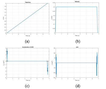 Figure 13. Motion parameters of autonomous vehicle, (a) traveling distance, (b) velocity, (c) acceleration and (d) jerk.
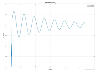 Figure 14. Actual response of carrier m2.
Conflict of Interest
The authors declare no conflict of interest.
- X. T. Truong and T. D. Ngo, “To Approach Human?: a unified framework for approaching pose prediction and socially aware robot navigation,” IEEE Transactions on Cognitive and Developmental Systems, vol. 10, no. 3, pp. 1-17, 2018, https://doi.org/10.1109/TCDS.2017.2751963.
- F. Yang and C. Peters, “Social-aware navigation in crowds with static and dynamic groups,” 11th International Conference on Virtual Worlds and Games for Serious Applications, pp. 1-4, 2019, https://doi.org/10.1109/VS-Games.2019.8864512.
- W.E. Singhose and N.C. Singer (1996), “Effects of input shaping on two-dimensional trajectory following,” IEEE Trans. on Robotics and Automation, 12(6), https://doi.org/10.1109/70.544771.
- Q. T. Truong, H. Q. T. Ngo, T. P. Nguyen, H. Nguyen and W. H. Kim,” A Novel Infrastructure Design of Industrial Autonomous System,” International Journal of Fuzzy Logic and Intelligent Systems, 19(2), pp. 103-111, 2019, http://doi.org/10.5391/IJFIS.2019.19.2.103.
- H. Q. T. Ngo, Q. C. Nguyen, W. H. Kim, ” Implementation of Input Shaping Control to Reduce Residual Vibration in Industrial Network Motion System,” 2015 15th International Conference on Control, Automation and Systems, pp. 1693-1698, 2015, http://doi.org/ 10.1109/ICCAS.2015.7364629
- L. Biagiotti and C. Melchiorri (2012), “FIR filters for online trajectory planning with time- and frequency domain specifications,” Control Engineering Practice, vol. 20, no. 22, pp. 1385-1399, 2012, https://doi.org/10.1016/j.conengprac.2012.08.005.
- H. Q. T. Ngo, T. P. Nguyen, T. S. Le, V. N. S. Huynh and H. A. M. Tran, “Experimental Design of PC-based Servo System,” International Conference on System Science and Engineering, pp. 733-738, 2017, https://doi.org/10.1109/ICSSE.2017.8030973 .
- L. Biagiotti, C. Melchiorri and L. Moriello (2015), “Optimal trajectories for vibration reduction based on exponential filters,” IEEE Trans. on Control Systems
Technology, vol. 24, no. 2, pp. 609-622, 2016, https://doi.org/10.1109/TCST.2015.2460693 . - H. Q. T. Ngo and M. H. Phan, “Design of an Open Platform for Multi-Disciplinary Approach in Project-based Learning of an EPICS Class,” Electronics, 8(2), 200, https://doi.org/10.3390/electronics8020200.
- L. Biagiotti and C. Melchiorri, Trajectory Planning for Automatic Machines and Robots, Springer-Verlag Berlin Heidelberg, 2008.
- H. A. M. Tran, H. Q. T. Ngo, T. P. Nguyen and H. Nguyen, “Implementation of vision-based autonomous mobile platform to control by A* algorithm,” International Conference on Recent Advances in Signal Processing, Telecommunications and Computing, pp. 39-44, 2018, http://doi.org/10.1109/SIGTELCOM.2018.8325802.
- N. M. Phu, V. Tuyen, T. T. Ngo, “Augmented heat transfer and friction investigations in solar air heater artificially roughened with metal shavings,” Journal of Mechanical Science and Technology 33, 3521-3529 (2019), http://doi.org/10.1007/s12206-019-0646-x
- L. Biagiotti and C. Melchiorri (2011), “Input shaping via b-spline filters for 3-d trajectory planning,” In IEEE/RSJ Int. Conf. on Intelligent Robots and Systems, http://doi.org/10.1109/IROS.2011.6094836.
- N. M. Phu, N. T. M. Trinh, “Modeling and experimental validation for off-design performance of the helical heat exchanger with LMTD correction taken into account,” Journal of Mechanical Science and Technology 30, 3357-3364 (2016), http://doi.org/ 10.1007/s12206-016-0645-0
- H. Q. T. Ngo, Q. C. Nguyen and W. H. Kim, “Implementation of input shaping control to reduce residual vibration in industrial network motion system,” International Conference on Control, Automation and Systems, pp. 1693-1698, 2015, http://doi.org/10.1109/ICCAS.2015.7364629.