
Advanced Hybrid Energy Harvesting Systems for Unmanned Aerial Vehicles (UAVs)
Volume 5, Issue 1, Page No 34-39, 2020
Author’s Name: Cuong Van Nguyen1, Toan Van Quyen2, Anh My Le2, Linh Hoang Truong2, Minh Tuan Nguyen2,a)
View Affiliations
1Thai Nguyen University of Information and Communication Technology, Vietnam
2Thai Nguyen University of Technology, Vietnam
a)Author to whom correspondence should be addressed. E-mail: tuanminh.nguyen@okstate.edu
Adv. Sci. Technol. Eng. Syst. J. 5(1), 34-39 (2020); ![]() DOI: 10.25046/aj050105
DOI: 10.25046/aj050105
Keywords: Unmanned Aerial Vehicle, (UAVs) – Drones, Solar cells, RF energy harvesting, Hybrid energy harvesting, Rechargeable batteries

Export Citations
The recent use of rotary-wing unmanned aerial vehicles (UAVs) has gained significant interest and continuously been implemented since they are used across the world for civilian, commercial, as well as military applications. The drawback of UAVs is the fight-time due to the limited battery capacity. Therefore, energy harvesting (EH), captured energy from the ambient environment is one of the effective measures to prolong the flight time for UAVs. This paper proposes the hybrid EH system, which can simultaneously harvest power from solar and radio frequency (RF) energy sources to significantly improve the energy issues for endurance longer flight UAVs. A 7-stage voltage multiplier circuit of the stand-alone RF-EH system is designed and simulated in this work. The stand-alone solar harvester is a solar panel. The DC output voltage from both of two energy sources is passed through a DC-DC boost converter and stabilizer. Simulation results can be deployed to power for the battery of UAVs in practice.
Received: 19 November 2019, Accepted: 30 December 2019, Published Online: 20 January 2020
1. Introduction
Recently, the use of flying platforms such as unmanned aerial vehicles (UAVs), popularly known as drones, is rapidly growing for many different applications in all commercial, civilian and military fields. The UAVs are very common with real-time monitoring, providing wireless coverage, remote sensing, search and rescue, delivery of goods, security and surveillance, precision agriculture, etc. UAVs have several key potential applications in wireless systems with their inherent attributes such as mobility, flexibility, and adaptive altitude. They can be equipped with cameras, sensors, and others to be more likely to perform various tasks such as surveillance and military services [1], search, and rescue in disaster damage [2], remote sensing [3, 4]. Additionally, they play an important role in the telecommunications infrastructure supporting the Internet of Things (IoT) vision [5] and wireless sensor networks (WSNs). Commercial UAVs commonly use the lithium and lithium-ion batteries that can maintain a fight time of about 20 to 40 minutes [6]. However, the energy limitations are a problem not only for UAVs but also for wireless sensor networks [7]. When UAVs do not use any alternative energy sources from the ambient environment, they may fail to several tasks due to the limited operating time. To complete various tasks for UAVs, the sustainable sources of power are
considered as an effective solution. Energy harvesting techniques are the process by which energy is derived from ambient sources such as solar energy, wind energy, vibration, electromagnetic energy, etc. They can be employed to extend the lifetime of battery for low power devices. However, this paper has taken into account the performance of hybrid RF- Solar EH system which is generally a workable script, ensuring for operation UAVs, it continues during all-day. Solar energy is harvested by solar panels and then converted into electrical energy. RF energy harvesting from ambient environments is responsible as an alternative power source for powering the day and night flight when there is no irradiation and thus no power can be extracted from solar panels. Both solar and RF energy sources contribute to the system with the same role. Hence, we propose a hybrid system which comprises of the RF energy harvesting and on-board solar cell for the UAVs long-endurance flight. Rechargeable batteries get support from both sources to operate the UAVs. To make sure the UAVs can avoid suddenly cutting power, the output power of the hybrid system is utilized for UAVs through the battery. All the circuits for either stand-alone or combined methods are designed with analysis and simulation results to clarify our methods. The hybrid method shows promising points to be more likely to improve the energy issues for UAVs in practical. In summary, the contributions of our paper are:
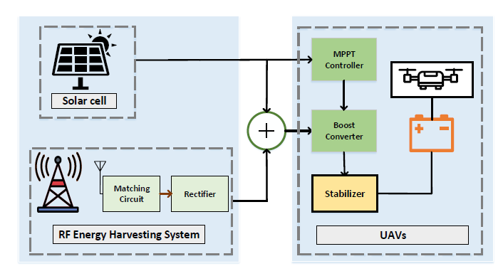 Figure 1: The block diagram of hybrid RF-Solar system for UAVs
- A new model of energy harvesting for UAVs is proposed.
- Analysis and Design with real circuits are provided for clarification.
- Recommendations in choosing suitable design including circuits, electronic elements to be able to achieve the most effective are provided.
The remainder of this paper is addressed as follows. All the related work is provided in Section 2. Theoretical Analysis and Design is mentioned in Section 3. Simulation results are provided with separated methods, RF energy, and solar energy harvesting, and combined both of them in Section 4. Conclusions and future work finally addressed in Section 5.
2. Related work
Radio-frequency (RF) energy can be collected from the environment, called ambient RF energy harvesting (RF-EH) which considered as free powering sources. Therefore, the utilization of the perpetual ambient RF-EH is more attractive than other dedicated energy sources of the WPT system. RF-EH system consists of three main components: (1) the receiving antenna, (2) the impedance matching circuit and (3) the voltage multiplier (VM). However, due to the low power density of the RF signal, the DC output voltage of the VM could be not as high as enough to supply energy for charging mobile electric devices (MEDs) such as UAVs. In order to overcome the above drawbacks, several methods are proposed for improving the VM circuit topologies in which the aim is improving conversion efficiency from ambient RF power to direct-current(DC) voltage at the given frequency band to power the low power devices/circuits such as the design of multiband and broadband rectifier [8], the choice of the number of stages [9,10], etc.
Besides, the RF/DC efficiency and DC output voltage is the proportion with the number of stages [11]. For examples, an equivalent incident signal of 0 dBm, a 5 stage voltage doubler circuit in [12] achieved Vout = 1.8 V while Devi et al. in [13] used 7 stages Schottky diode voltage doubler circuit with the result obtained is DC output voltage of 5.0 V. In the other hand, in wide-bandwidth RF applications that require smaller form factors or reduced cost, direct RF energy source is a suitable choice. Similar to the ambient RF system, a direct RF system also needs to improve the efficient RF-DC conversion system. The existed solutions applied for charging battery UAVs can be mentioned as designing a dual-band rectifier with impedance matching [14], designing a light-weight flexible rectenna array mounted on the UAV body micro-controller drove power management circuit that enables efficient battery charging [15], etc. Another energy source, the solar energy considered as harvesting energy of the WPT system, is the cleanest and most plentiful renewable energy source available. Solar panels are used to absorb solar energy and convert into electric power through the photovoltaic (PV) effect. Therefore, solar energy harvesting technologies are widely used for various applications, especially generating electricity for domestic, agriculture, and industry, etc. In reality, the solar system poses many issues in terms of environmental conditions, initial high capital cost, low efficiency, etc. To eliminate these above issues, the efficiency of the solar cell system can be improved by applying methods such as a maximum power point tracking (MPPT) techniques [16, 17], a solar power management system (SPMS) [18] and boost converter in [19,20] which can get the high efficiency with slight weight. Besides, we also need to choose the most suitaestble materials for manufacturing solar panels. In [21], thin-film solar cells is fabricated with Cu2ZnSnS4 (CZTS) absorber layers. The battery is the storage place for UAV energy. Wireless power transfer is the most popular technology to charge for the battery of UAVs. This technology satisfies high-performance power transmission over short to long distances with various methods such as mganetic resonant coupling, laser beaming, etc. [22].
Harvester aforementioned circuits can be developed to collect energy from stand-alone either RF or solar source. In this paper, we proposed a hybrid RF-solar harvesting system simultaneously harvests energy from solar and RF sources readily available in the ambient environment for the purpose of charging UAV batteries.
3. Theoretical Analysis and Design
This section provides an analysis of each stand-alone source system and also the design to combine suitable components to build the hybrid system. All the designs will be simulated to clarify the methods and also the recommendations.
3.1 RF energy harvesting
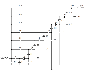 Figure 2: RF energy harvesting
This model includes three main components, antennas, matching circuit and rectifier. After receiving RF signal by antenna, a matching circuit is installed in series between RF signal source and the rectifier to be able to mitigate the dissipated power for these parts. The rectifier circuit converts the input of an AC voltage into a DC output. In each rectifier stage, the voltage multiplier method is used to increase the harvested output voltage from narrow frequency input [10]. The seven-stage voltage multiplier (VM) circuit is designed and simulated to be shown in Figure 1. The 7-stage VM circuit consists of passive components such as stage diodes (D1D14) and stage capacitances (C1–C14). Each stage is stacked onto the previous stage.
3.2 Solar enery harvesting
Solar panels are deployed to convert light from the sun into electricity using semiconducting materials that exhibit the PV effect. They have disadvantage sides of varied efficiency value under weather conditions. In Proteus software [23], if its sunny bright day then solar panel normally gives in the range of 15 V to 19 V. On a cloudy day, it could vary between 8 V and 12 V. Solar panels obtain output ranges from 2 V to 6 V in the night time. In general, choosing solar panels could affect the output voltages. In other words, depending on the desired voltage needed for each UAV system, we can choose a suitable one for the system. This also depends on the intensity of sunlight in a deploying area.
In this paper, in order to keep the UAV system light and active, the number of cells should be limited. In addition, we want to improve the efficiency of solar battery charging in the night time that motivates us to choose the output voltage as 5 V. Based on this chosen voltage level, the solar panels will be chosen accordingly. Therefore, DC-DC boost power converters are also chosen in the systems to step up the output voltage of a solar panel for a given set of conditions and maximize the efficiency of stand-alone solar energy. The circuits will be provided in the next section.
3.3 Boost Converter and Stabilizer
This boost converter is a DC to DC converter with an output voltage greater than the input voltage. In this converter, an inductor is used to resist any changes in current by creating and destroying a magnetic field. While a transistor switch is typically a MOSFET to pulse width modulate the voltage into an inductor. Maximum power point tracking controls the duty cycle of the MOSFET’s switching in order to achieve the desired power value. Figure 3 illustrates a circuit diagram used for the Proteus simulation of a boost converter.
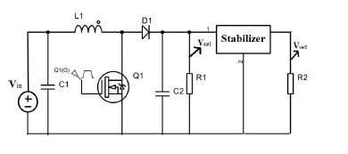 Figure 3: DC-DC Boost converter and Stabilizer
The key principle of the boost converter can be divided into two states in one cycle: state 1 and state 2. State 1: when MOSFET Q1 is switched on at time ton, the input current rises and flows through inductor L1 and MOSFET Q1. State 2: when MOSFET Q1 is switched off at tof f = (1 – ton), the input current flows through L1, diode D1, C2, and load R1. The energy stored in inductor L1 flows through the load [24].
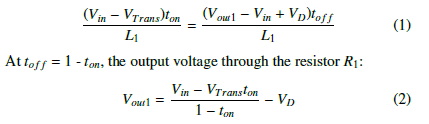 Here VD is the voltage drop across the diode D1, and VTrans is the voltage drop across the transistor MOSFET Q1. Vout1 is the output voltage across the resistor R1.
Since the output voltage through the load R1 is unstable, the stabilizer is added after the load to fix the output voltage of the load. Therefore, the purpose of this circuit is to measure the output voltage Vout2 across the resistor R2.
3.4 The Design of Hybrid Energy Harvesting System
This paper proposes a hybrid RF-Solar system designed to harvest energy from two energy sources: Solar and RF energy. In order to maximize UAVs flight endurance, the conventional power supply of UAVs is integral with RF and solar energy harvesting systems. As shown in Figure 1, our hybrid system comprised of two main components, that is the energy sources which include RF and solar energy and amplifier circuits which include MPPT controller, boost converter and stabilizer. Solar cells absorb sunlight as a source of energy to generate DC electricity. Following in the solar cell design of the solliance thin film solar research [25] in which they combine a semi-transparent Perovskite cell and a CIGS cell to achieve the power conversion efficiency of 23% on a flexible solar cell.
RF energy is collected by an antenna through the matching circuit to ensure the maximum power delivery to voltage multiplier (VM). The RF power is converted from a lower AC/RF voltage to a higher DC voltage by voltage multiplier. A voltage multiplier (VM) is a special case of the rectifier circuit, including capacitors and diodes. By comparing the results of experiments [10,12,13], and the trade-off between the high voltage and power loss, the 7-stage voltage multiplier is chosen.
Due to the changing temperature and variation of irradiation, the efficiency of solar panels is low. A maximum power point tracking (MPPT) circuit is used for two purposes. The first is to find the amount of sunlight index harvested by solar cells and MPPT circuits extract the maximum achievable power from the PV generator. The second is support boost converter circuit to adjust the panel DC output voltage to the desired value and the duty cycle of the DC-DC converter. Two DC power sources are fed into the boost converter which is a basic power converter that operates by simultaneously closing and opening of a high frequency switches like MOSFET to step-up voltage. However, it has a drawback such as the oscillating voltage. The stabilizer is used to fix the output voltage value which supplies the battery of UAVs. Our paper assumes all parameters of the drone M200 V2 and its intelligent fight battery (TB55) that is composed of 6S Li-Po cells that correspond to a battery voltage of 22.8 V, with a capacity between 7660 mAh [26].
4. Simulation Results
In this section, we independently simulate RF and solar system and then combine them as the hybrid system to show the improvement. The UAV/Drone, named M200-V2 is chosen for our simulations. Based on that, all the circuits are designed to support the UAV. All the simulation results would be provided to be suitable for the attached batteries.
4.1 Solar Energy Standing Alone
As mentioned above, we assume the output voltage of the solar panel in Proteus simulation is 5 V which is delivered directly to the boost converter. The output voltage of the solar system with the boost converter significantly increases compared to the original value. After 40 sec, the DC voltage increases from 5 V to 15.3189 V and the current from 5e−12 A to 0.6963 A, as shown in Figure 4. Since the output voltages from the boost are unstable, a stabilizer is used to provide a stable and secure power supply to the devices.
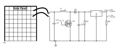 Figure 4: The solar panel connected with DC-DC boost converter
This allows the system to keep the voltage stable and to protect the systems from almost the main problems that may happen. With all of the effort to improve the solar systems, we only achieve the output voltages that are smaller than the voltages required by the drones as 22,8 V. Therefore, the hybrid energy harvesting system should be proposed to be able to adapt the power supply for the batteries of UAVs.
4.2 RF Energy Harvesting Standing Alone
In this work, the DC output voltage obtained through simulation as 6.62V, shown in Figure 2. This result is comparatively much better than in reference [13].
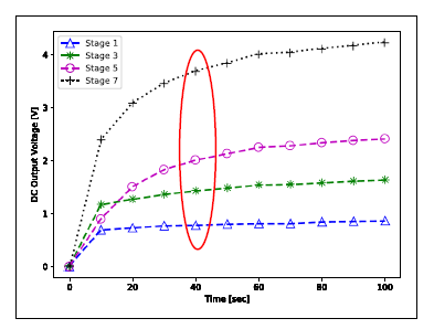 Figure 5: DC output voltage verses rise time of voltage multiplier circuit through the stages
The number of stages in the rectifier has a dramatic influence on the DC output voltage of the RF energy harvesting circuit, shown in Figure 3. Settling time more than 100 second, the DC output voltage is obtained Voutput = 0.85 V at one stage;Voutput = 1.62 V at 3-stage; Voutput = 2.4 V at 5-stage; and Voutput = 4.22 V at 7-stage. Because of the trade-off between the value of the DC output voltage and the time response, we choose the stopping time at 40 sec and achieve Voutput = 3.68 V with 7-stage. At this point, the voltage output is quite stable which would be enough to support the UAVs.
4.3 The Proposed Hybrid Energy Harvesting System
This simulation is aimed to take the suitable output voltage for the battery requirements of the UAV M200-V2.
As shown in Figure 6 and Figure 7, the charging voltage and current of the battery reach a stable level after one second. The one second can be acceptable because this is the response time to charge the battery rather than supply power directly to the UAV, so it does not require strictly the real-time. After that, the voltage and current values are stable at 23.15 V and 1.05 A. These results also overcome the previous systems that show promise.
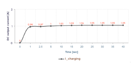 Figure 6: Time response of DC output current for the battery of UAVs
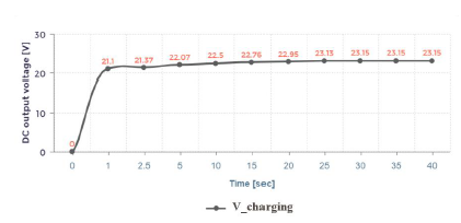 Figure 7: Time response of DC output voltage for the battery of UAVs
From the analysis of these simulations, the measured DC voltage and currently collected from RF energy, solar energy, and hybrid models are addressed in Table 1. The output current and voltage of the hybrid system are always greater than the output current and voltage of stand-alone RF or solar harvester circuit before adding the boost converter.
Table 1: The output current and voltage of Solar, RF and Hybrid system without a boost converter
| Solar Energy | RF Energy | Hybrid | |
| Current (A) | 5e−12 | 3.677e−8 | 0.32 |
| Voltage (V) | 5 | 3.68 | 7.17 |
As shown in Table 1, both the voltage and the current are not big enough to supply to the battery of the UAV/Drone M200-V2. Therefore, we have Table 2 where the circuit adds the boost converter and a stabilizer. The results show the desired levels that we always expected. We finally achieve the level suitable for the systems.
Table 2: The output current and voltage of Solar, RF and Hybrid system with a boost converter
| Solar Energy | RF Energy | Hybrid | |
| Current (A) | 0.69 | 0.48 | 1.05 |
| Voltage (V) | 15.3 | 9.77 | 23.15 |
5. Conclusions and Future Work
In this paper, the proposed hybrid solar-RF energy harvesting overtakes stand-alone solar and RF harvesting systems and shows promise. At any time during the day, the efficiency of the hybrid harvest system is critically increased more than stand-alone systems, so the flight time of UAVs is significantly extended. Since the standalone RF and solar systems are abruptly drop, so this performance of UAVs significantly improve the situations. By utilizing the hybrid system, this problem is tackled. A new design with all results is shown to clarify the problems.
Currently, the capacity of the battery storage has not been mentioned that would be the next step to improve the systems. Besides, it is possible to improve the efficiency and reduce the overshooting time by using fuzzy or PSO (particle swarm optimization) algorithm for controlling the duty cycle of the DC-DC boost converter. Further, we would utilize this hybrid source to directly supply for the UAVs and to charge for the battery of the UAVs at the same time.
6. Acknowledgement
This work is supported by Thai Nguyen University of Technology (TNUT), Vietnam, project T2018-B40.
- P. Lewis, “Cctv in the sky: police plan to use military-stylespy drones,” The Guardian, vol. 23, p. 1, 2010.
- S. Chandrasekharan, K. Gomez, A. Al-Hourani, S. Kandeepan,T. Rasheed, L. Goratti, L. Reynaud, D. Grace, I. Bucaille,T. Wirth, et al., “Designing and implementing future aerial communication networks,” IEEE Communications Magazine, vol. 54, no. 5, pp. 26–34, 2016.
- U. Niethammer, M. James, S. Rothmund, J. Travelletti, andM. Joswig, “Uav-based remote sensing of the super-sauze land- slide: Evaluation and results,” Engineering Geology, vol. 128, pp. 2–11, 2012.
- E. R. Hunt, W. D. Hively, S. Fujikawa, D. Linden, C. S. Daugh- try, and G. McCarty, “Acquisition of nir-green-blue digital pho- tographs from unmanned aircraft for crop monitoring,” RemoteSensing, vol. 2, no. 1, pp. 290–305, 2010.
- N. H. Motlagh, T. Taleb, and O. Arouk, “Low-altitude un- manned aerial vehicles-based internet of things services: Com- prehensive survey and future perspectives,” IEEE Internet of Things Journal, vol. 3, no. 6, pp. 899–922, 2016.
- B. Lee, S. Kwon, P. Park, and K. Kim, “Active power man- agement system for an unmanned aerial vehicle powered by solar cells, a fuel cell, and batteries,” IEEE Transactions on Aerospace and Electronic Systems, vol. 50, no. 4, pp. 3167– 3177, 2014.
- M. Nguyen, H. Nguyen, A. Masaracchia, and C. Nguyen, “Stochastic-based power consumption analysis for data trans- mission in wireless sensor networks,” EAI Endorsed Transac- tions on Industrial Networks and Intelligent Systems, vol. 6, no. 19, 2019.
- A. Collado, S.-N. Daskalakis, K. Niotaki, R. Martinez, F. Bo- los, and A. Georgiadis, “Rectifier design challenges for rf wireless power transfer and energy harvesting systems,” Ra- dioengineering, vol. 26, no. 2, pp. 411–417, 2017.
- G. DiCataldo and G. Palumbo, “Design of an nth order dickson voltage multiplier,” IEEE Transactions on Circuits and Sys- tems I: Fundamental Theory and Applications, vol. 43, no. 5, p. 414, 1996.
- P. Nintanavongsa, U. Muncuk, D. R. Lewis, and K. R. Chowd- hury, “Design optimization and implementation for rf energy harvesting circuits,” IEEE Journal on emerging and selected topics in circuits and systems, vol. 2, no. 1, pp. 24–33, 2012.
- R. E. Barnett, J. Liu, and S. Lazar, “A rf to dc voltage conver- sion model for multi-stage rectifiers in uhf rfid transponders,” IEEE Journal of solid-state circuits, vol. 44, no. 2, pp. 354– 370, 2009.
- T. R. Ansari, A. Khan, and I. Ansari, “Wireless charging of mobile battery via optimization of rf energy harvesting system,” International Journal of Scientific & Engineering Research, vol. 6, no. 7, 2015.
- K. K. A. Devi, N. M. Din, and C. K. Chakrabarty, “Optimiza- tion of the voltage doubler stages in an rf-dc convertor module for energy harvesting,” Circuits and Systems, vol. 3, no. 03, p. 216, 2012.
- K. Suri, M. Mohta, and A. Rajawat, “Design of a dual band rectifier circuit for drone powering applications,” in 2017 8th International Conference on Computing, Communication and Networking Technologies (ICCCNT), pp. 1–4, 2017.
- S. Dunbar, F. Wenzl, C. Hack, R. Hafeza, H. Esfeer, F. Defay,S. Prothin, D. Bajon, and Z. Popovic, “Wireless far-field charg- ing of a micro-uav,” in 2015 IEEE Wireless Power Transfer Conference (WPTC), pp. 1–4, IEEE, 2015.
- M. Kerdegari, “Optimization and design in control of intel- ligent solar uav using mppt,” in Iranian Aerospace Society Conference, 2012.
- E. Sener, I. Turk, I. Yazar, and T. H. Karakoc¸, “Solar powered uav model on matlab/simulink using incremental conductance mppt technique,” Aircraft Engineering and Aerospace Tech- nology, 2019.
- J.-K. Shiau, D.-M. Ma, P.-Y. Yang, G.-F. Wang, and J. H. Gong, “Design of a solar power management system for an experi- mental uav,” IEEE transactions on aerospace and electronic systems, vol. 45, no. 4, pp. 1350–1360, 2009.
- R. Patel, S. K. Sinha, et al., “Performance analysis of pv system integrated with boost converter for low power applica- tions,” in Advances in Interdisciplinary Engineering, pp. 879– 890, Springer, 2019.
- A. Azeem, M. K. Ansari, M. Tariq, A. Sarwar, and I. Ashraf, “Design and modeling of solar photovoltaic system using seven- level packed u-cell (puc) multilevel inverter and zeta converter for off-grid application in india,” Electrica, vol. 19, no. 2, pp. 101–102, 2019.
- J. J. Scragg, P. J. Dale, and L. M. Peter, “Towards sustain- able materials for solar energy conversion: Preparation and photoelectrochemical characterization of cu2znsns4,” Elec- trochemistry Communications, vol. 10, no. 4, pp. 639–642, 2008.
- M. T. Nguyen and T. H. Nguyen, “Wireless power transfer: A survey of techniques, and applications on communication networks,” 2018.
- “Solar panel library for proteus online: theengineeringprojects.com/2018/07/solar-panel-library-for- proteus.html.”
- P. W. Chan, “Dc-dc boost converter with constant output volt- age for grid connected hotovoltaic application system,” in Industrial Electronic Seminar, 2010.
- “23% efficiency for flexible cells – for real?, https://www.solliance.eu/2019/23-efficiency-for-flexible- cells-for-real/.”
- T. Campi, S. Cruciani, and M. Feliziani, “Wireless power trans- fer technology applied to an autonomous electric uav with aoil,” Energies, vol. 11, no. 2, p. 352, 2018.