Alleviation of Nonlinear Impact Using PAPR Hybrid Technique in CO-OFDM Systems

Adv. Sci. Technol. Eng. Syst. J. 4(6), 423–429 (2019);
 DOI: 10.25046/aj040653
Orthogonal Frequency Division Multiplexing (OFDM) is a modulation format that has recently attracted lots of consideration interior the long-haul fiber-optic transmission community. The most important advantage of optical OOFDM is its unlimited capability of canceling Inter-Symbol Interference (ISI) caused by Chromatic Dispersion (CD) and Polarization-Mode Dispersion (PMD). Specifically, Coherent OOFDM (CO-OFDM) presents a good and effective modulation method in modern optical communication systems. However, due to its high Peak to Average Power Ratio (PAPR), the performance of CO-OFDM is affected by nonlinear impairments. In this paper, we propose a new joint nonlinear technique; L3-by-3; with a distortion technique; clip-ping; that bypass the requirement for the use of any side information (SI) to minimize the high PAPR value of the transmitted signal and consequently improve various fiber nonlinear impacts through PAPR reduction. The simulation results reveal dependable and excellent signal recapture at the receiver and an effectively minimized PAPR level at the sender side.
1. Introduction
Because of the advantages and qualities of the OFDM system such as high spectral efficiency, this has led to its use in different modern communication applications. Furthermore, it is worthwhile noting that many authors have made the OFDM the first candidate for use in high-speed communications applications and high data rate systems. [1]. The OOFDM system is rated depending on the application in which it is used into two types, the first type is called Direct Detection OOFDM(DD), where a single photodiode is utilized for detection in the receiver.The second type is called Coherent Detection OOFDM (CO-OFDM) Which utilized an optical mixing is employed with a Local Oscillator (LO) in a coherent optical receiver. [2, 3]. The optical transmission system suffers from several disadvantages , especially when using a higher order of mapping M-PSK or M-QAM, where (M) is the order of mapping. these impairments have been discussed in many studies and articles and are classified as linear and non-linear. [4]. Nevertheless, coherent systems that utilizing Digital Signal Processing (DSPs) permits the compensation of system weakness. In addition, there are many ways to process the signal and compensate the impairments. Some of these processes are used in the receiving transmitter side, some of them employed in the optical channel, while the others are used in the receiver side.
The synchronization and balance method is an example of the methods used to compensate impairments in the optical channel as demonstrated in [5, 6]. Moreover, there are other methods that can be utilized to compensate the impairments that have occurred to the signal in the optical channel, such as Optical Phase Conjugate (OPC) to reduce nonlinearity, and Dispersion Compensated Fiber (DCF) to mitigate the impact of CD on the signal [7, 8]. Additionally, some methods that based on DSP are utilized in the transmitter side, such as phase-conjugated twin wave method [5], where some of such methods depend on diminishing the Peak to Average Power Ratio (PAPR) of the transmitted signal. A worthy reduction can also be gained when using one of these techniques, such as Selective Mapping (SLM) [6], Partial Transmit Sequence (PTS) [7], and non-linear transforms [8].
In this paper, the primary objective is to mitigate the impact of phase noise and nonlinearity in a CO-OFDM system employing 4QAM and 16QAM modulation through PAPR reduction in the system using the VPI software. The novel contribution of this article the use of the nonlinear method; L3by3; joined with the clipping distortion technique; for the first time in order to produce a new combining technique to lessen the nonlinear impact through PAPR reduction for two modulation order with 10 Gbps bitrate.
2. CO-OFDM System Principle
In general, the concept behind OFDM is that one stream with high data rate is converted into different streams with lower data rates. It has been evince that these streams can be sent in parallel, offering more extensive symbol periods than single bearer style. Moreover, in OFDM these parallel streams are modulated by using one type of modulation such as, QAM, BPSK, and QPSK. [9]. The main factor behind the use of OFDM In modern radio norms is the high spectral efficiency that provides due to the presence of subcarriers which are orthogonal to each other. Because of its normal flexibility to reduce the impacts of chromatic dispersion [2]. Although the CO_OFDM system It is complex in design from the transmitter side but provides spectral efficiency, future sensitivity and immunity to polarization dispersion. CO_OFDM system divides into five sections: Radio Frequency (RF) OFDM transmitter, optical transmitter, optical channel, optical receiver and RF receiver. Figure 1 shows the primary sections of a CO-OFDM system.
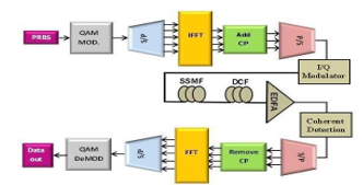 Figure 1 CO-OFDM system Block Diagram
In the transmitter, a serial binary data flow is obtained from a Pseudo-Random Binary Sequence generator (PRBS) and mapped into symbols using QAM mapping. In this study 4 and 16-QAM orders are considered where every two adjusted bits are mapped into one symbol in the case of 4-QAM, while in 16-QAM each symbol contains 4 bits. The serial data stream is converted to a parallel form before being passed to the Inverse Fast Fourier Transform (IFFT) block. In IFFT the block of data is transformed from the frequency domain into the time domain, and a cyclic prefix (CP) is added at the beginning of each time-domain OFDM symbol to eliminate Inter-Carrier Interference (ICI) and Inter-Symbol Interference (ISI) at the receiver. Afterward, the signal is converted from a parallel to a serial form (P/S) to send through the optical channel. The optical part of the system consists of an IQ modulator block which contains two Mach-Zehnder Modulators (MZMs) with a continuous wave (CW) laser that are utilized to up-converter the real/imaginary components of the signal, from the radio frequency(RF) domain to the optical domain.
In order to obtain the optical modulated signal, the signals that come from the two branches which have a phase difference of 90 are combined [10]. The subsequent part of the system is the fiber optic channel, which contains three processes: (i) Standard Single Mode Fiber (SMF) using to send optical signal.; (ii) compensating the dispersion in the optical channel using a Dispersion Compensating Fiber (DCF), where, the DCF, which is treated as a special kind of fiber optic that has a considerable negative dispersion, is used after the standard SMF [11] and (iii) amplifying the strength of signals being carried through the fiber optic channel using an Erbium-Doped Fiber Amplifier (EDFA) as well as compensating the attenuation induced by the optical fiber. The third part of the system is the receiver, which contains a coherent reveal block with laser used as a local oscillator, which is used to convert the optical signal to an RF signal. The coherent receiver can convert an optical-signal to a baseband electrical signal, where the 90° phase difference between the I and Q components is generated by optical hybrids and producing a phase shift equals of 180° among balanced detection. The final part of the system is the OFDM decoder, which consists of a serial to parallel converter, where data is converted from a serial into a parallel form, removing CP and executing a Fast Fourier Transform (FFT). To retrieve the transmitted information, the FFT is first used to turn the signal into the frequency domain. The outgoing data from the FFT is then switched to a sequential order to perform the de-modulation process and obtained the original data. The OFDM signal is involve of a substantial number of subcarriers. the addition of the power of (N) subcarriers that have the same phase will give top power (N) by the normal power. However, a huge PAPR increases the Nonlinear (FNL) impairments, which diminish the performance of the optical system. the OFDM consist of (N) data sequences of vector U(Uk (k=0,1,.., N-1)), which will be sent in side by side. One OFDM data symbol is:
![]() where fk is the subcarriers frequency spacing, Uk is the kth information symbol vector and u(t) is the baseband time domain OFDM signal after IFFT. the PAPR is relies upon the input information. As such, PAPR can be computed by finding the ratio between the peak power to the average power of the signal [12]. The equation of PAPR can then be written as:
where fk is the subcarriers frequency spacing, Uk is the kth information symbol vector and u(t) is the baseband time domain OFDM signal after IFFT. the PAPR is relies upon the input information. As such, PAPR can be computed by finding the ratio between the peak power to the average power of the signal [12]. The equation of PAPR can then be written as:
![]() where E[|()|2] is the average power of the OFDM. The Cumulative Distribution Function (CDF) is the most frequently utilized parameters, and is utilized to gauge the performance of any PAPR technique. Regularly, the complementary cumulative distribution function (CCDF) is used when PAPR value exceeds the threshold. To find the probability that PAPR of an OFDM signal exceeds the threshold (p0), assume the following complementary cumulative distribution function (CCDF) for non- overlapping sampling;
where E[|()|2] is the average power of the OFDM. The Cumulative Distribution Function (CDF) is the most frequently utilized parameters, and is utilized to gauge the performance of any PAPR technique. Regularly, the complementary cumulative distribution function (CCDF) is used when PAPR value exceeds the threshold. To find the probability that PAPR of an OFDM signal exceeds the threshold (p0), assume the following complementary cumulative distribution function (CCDF) for non- overlapping sampling;
 3. Proposed Technique
Generally, the nonlinear method L3-by-3 was first discussed in [14] for wireless OFDM system. This method is based on the Sliding Norm Transform (SNT) based PAPR reduction method [15]. Here, we propose, for the first time, using a combination of clipping and L3by3 in CO-OFDM system. Let x be a real vector with N samples, x=(x1,x2,x3,….,xN).The sliding norm transformer that can be used in the transmitter side is then defined as follows:
![]() The parameter (α) adjusts the PAPR of the transformed output. In other words, different values for PAPR can be obtained by changing α value, which indicates the possibility of setting a value of PAPR by selecting the optimum value of α. The L3by3 transformer technique effectively lowers the PAPR of the CO-OFDM signals when compared with other techniques. The process of restoring x signals samples at the receiving end is done using the following Equation:
The parameter (α) adjusts the PAPR of the transformed output. In other words, different values for PAPR can be obtained by changing α value, which indicates the possibility of setting a value of PAPR by selecting the optimum value of α. The L3by3 transformer technique effectively lowers the PAPR of the CO-OFDM signals when compared with other techniques. The process of restoring x signals samples at the receiving end is done using the following Equation:
![]() where sign(0) is the Signum function. It can be noted that from Equation (5) data at the receiver can be recovered and the transmitted information can be obtained. The proposed hybrid technique is a combination between the clipping method and the L3-by-3 method and can be described by:
where sign(0) is the Signum function. It can be noted that from Equation (5) data at the receiver can be recovered and the transmitted information can be obtained. The proposed hybrid technique is a combination between the clipping method and the L3-by-3 method and can be described by:
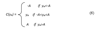 where C(yn) is the clipping signal, and A is a predetermined clipping level that can be defined as:
![]() where Pin represents the mean input power of the OFDM signals, and CR is the clipping ratio. The principle of clipping technique is based on setting the maximum value of the input signal to a predetermined value if exceeded it will be clipped, otherwise, the input signal is transmitted without any change. In general, the clipping ratio is used to determine the level of clipping. More specifically, the clipping method is considered as a non-linear process that causes (in & out) band distortion. In other words, the out-band distortion causes spectral extension and can be taken away by filtering out the signal after clipping. On the other hand, the in-band distortion limits the Bit Error Rate (BER) and can be disposed of by performing clipping with the adequately oversampled OFDM signals (e.g., L ≥4 where L is the oversample factor), resulting in a less degraded BER performance. To achieve an excellent PAPR performance, the L3by3 technique is combined with the clipping technique, where despite the increase in the BER of the system due to the clipping technique such an adverse of in-band distortion impact is eliminated, through the L3by3 technique, which reduces the number of signals exceeding the threshold value.
where Pin represents the mean input power of the OFDM signals, and CR is the clipping ratio. The principle of clipping technique is based on setting the maximum value of the input signal to a predetermined value if exceeded it will be clipped, otherwise, the input signal is transmitted without any change. In general, the clipping ratio is used to determine the level of clipping. More specifically, the clipping method is considered as a non-linear process that causes (in & out) band distortion. In other words, the out-band distortion causes spectral extension and can be taken away by filtering out the signal after clipping. On the other hand, the in-band distortion limits the Bit Error Rate (BER) and can be disposed of by performing clipping with the adequately oversampled OFDM signals (e.g., L ≥4 where L is the oversample factor), resulting in a less degraded BER performance. To achieve an excellent PAPR performance, the L3by3 technique is combined with the clipping technique, where despite the increase in the BER of the system due to the clipping technique such an adverse of in-band distortion impact is eliminated, through the L3by3 technique, which reduces the number of signals exceeding the threshold value.
4. System Setup and Simulation Results
This section introduces the simulation of a CO-OFDM system with PAPR reduction using the VPI Transmission- Maker and MATLAB software packages. The global parameters set for the simulations and their values are presented in the Table (1).
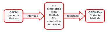 Figure 2 CO-OFDM system setup
| Table1. The CO-OFDM system Simulation parameters | ||
| General parameters | ||
| Bit-rate | 10Gbps | |
| Sample-rate | 40Gbps | |
| Sequence-length | 8192 | |
| Samples-per-bit | 2-bit | |
| Mapping order | 4QAM,16QAM | |
| OFDM-parameters | ||
| Sub-carriers | 128 | |
| Cyclic-prefix | 1/8 | |
| CW Laser & Local Oscillator | ||
| Carrier freq. | 193.1THz | |
| Power in dBm | 5dBm | |
| Line-width | 0.1MHz | |
| SMF&DCF | ||
| SMF length in km | 50km | |
| DCF length in km | 5km | |
| Number of loops | 10 | |
| DCF attenuation | 0.5dB/km | |
| DCF dispersion | -160ps/nm/km | |
| SMF dispersion | 16ps/nm/km | |
| SMF attenuation | 0.2dB/km | |
| Optical Amplifier DFA | ||
| Gain | 13dB | |
| Noise Figure | 4dB | |
| Α | 0.2 | |
The OFDM signal generation and PAPR reduction were performed using MATLAB interfaced with VPI using the MATLAB Co-Simulation features, as shown in Figure (2).
First of all, referring to Equation (4) the control parameter α investigated for L3by3 for the 4-QAM and 16-QAM mapping orders. Table (2) shows the results obtained for PAPR at different values of α. The results show that α is directly proportional to PAPR. In other words, as α values change from 0 to 1, the value of PAPR increases, where the lowest PAPR value is obtained when the value of α is 0.1.
Table 2 PAPR values for different values of α
| PAPR value in dB at probability of 10-4 | |||||||
| original | 4QAM | 11.5 | |||||
| 16QAM | 11.2 | ||||||
| α | 0.1 | 0.2 | 0.4 | 0.6 | 0.8 | 1 | |
| L3by3 | 4QAM | 6.35 | 7.75 | 8.4 | 9.1 | 9.4 | 10.1 |
| 16QAM | 6.75 | 7.6 | 8.5 | 9 | 9.55 | 10.2 | |
Figure 3 (a) and (b) plot the CCDF as a function of PARP of the original signal without using any reduction technique for PAPR ; the CCDF when using a clipping for the signal at a clipping level 0.6, the CCDF when using L3by3 at α = 0.1; and the proposed hybrid technique for 4-QAM and 16-QAM optical OFDM signals, respectively.
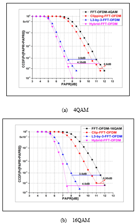 Figure 3 A comparison of the CCDF vs. PAPR performance of a CO-OFDM system using a variety of techniques
Table 3 summarizes the results of PAPR reduction using the proposed technique at CCDF probability values of 10−4.
Table 3 PAPR for the proposed technique at CCDF probability 10-4
| PAPR Value in dB at Probability 10-4 | ||||
| original | clipping | L3by3 | L3by3+clip | |
| 4QAM | 11.9 | 0.6 | 3.6 | 4.35 |
| 16QAM | 11.9 | 0.95 | 3.5 | 4.5 |
The table shows the efficiency of the proposed hybrid method in reducing the PAPR compared to using the L3by3 method and the clipping method separately. In addition, the suggested method has been compared with the other methods used to reduce PAPR in terms of their effectiveness in PAPR reduction as in table(4).
Table 4 Comparison between the suggested method and other PAPR reduction methods
| PAPR Value in dB at Probability 10-4 | ||||
| Method | original | Hybrid | Reduction | Mapping |
| IPTS+CF[16] | 10.5 | 7.32 | 3.18 | QPSK |
| IPTS+MCF[16] | 10.5 | 6.18 | 4.32 | QPSK |
| Hadamard+m-law[17] | 13.4 | 11.4 | 2 | QPSK |
| L3by3+clipping | 11.9 | 7.55 | 4.35 | QAM |
To check the efficiency and effects of the PAPR reduction on the system when changing distance, Figures (4) and (5) illustrate distance vs. Quality Factor (QF) and BER vs. distance respectively, for the system without using any technique to reduce PAPR ; for the system using the L3by3 ; and for the system using the proposed hybrid method. From figures, it is possible to deduce that the suggested hybrid method improves the QF and the BER for the system, where the results obtained for these parameters in the case of the hybrid method are better than those of the original system and those of system employing the L3by3 method. Table (5) summarizes the results obtained for QF from Figure (4).
As can be noted from Figure 4, the QF for the conventional CO-OFDM is good as well as the QF for both schemes at low distances (i.e. < 250 km), due to the reduction of the effect of chromatic dispersion as well as attenuation due to the presence of DCF that eliminates the effect of dispersion as well as the EDFA which minimizes the impact of attenuation. However, when we increase the launch power of the signal the distance will increases, thus increasing the nonlinear effects due to the Kerr effect, which reduces the performance of the system. As such for a larger distance (i.e. > 250 km), the proposed scheme outperforms the L3by3 method and the traditional CO-OFDM as it has the lowest PAPR, which reduces the fiber nonlinearity caused by the Kerr effect compared to the other two schemes (see Figure 3).
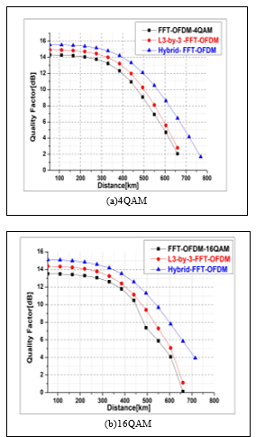 Figure 4 QF vs. distance for (a) 4-QAM and (b) 16-QAM
Table.5. QF for CO-OFDM at different distances using different PAPR reduction techniques
| Quality Factor in dB | ||||
| Distance [km] | Mapping | Original | L3by3 | Hybrid |
| 275 | 4QAM | 13.7 | 14.4 | 15.2 |
| 16QAM | 13 | 13.7 | 14.5 | |
| 550 | 4QAM | 6.9 | 8 | 10.5 |
| 16QAM | 5.8 | 7.2 | 9.6 | |
The 4-QAM and 16-QAM constellation points for the three aforementioned schemes presented in Table 5 show the QF improvement when the proposed scheme is considered compared to the other two schemes. For example, a QF improvement of 1.5 dB and 0.8 dB is obtained for the proposed scheme compared to the traditional CO-OFDM and L3by3 schemes, respectively, when 4-QAM is considered as a modulation order at a distance of 257 km. The table also illustrates that increasing the distance to 550 km for the same modulation order (i.e. 4-QAM) results in a 4.5 dB and 2.4 dB QF improvement for the proposed scheme compared to the traditional CO-OFDM and the L3by3 schemes, respectively.
Figure 5 shows the received constellation points of the traditional CO-OFDM, as well as the L3by3 and the proposed hybrid schemes. As illustrate in Figure 5 (a) for the 4-QAM mapping order, it is shown that an excellent constellation diagram for the original system (i.e. CO-OFDM) is obtained for the short fiber length with excellent QF. However, the 4-QAM constellation points of this scheme becomes worse for long fiber distances, as its QF becomes low. In the case of the L3by3 and the proposed Hybrid method, the performance remains good with increased distances, where a good quality factor can be obtained for up to 550 km for the system with the L3by3 method, and for up to 660 km for the system with the proposed Hybrid technique.
Additionally, Figure 5 (b) shows the constellation points of 16-QAM with and without the use of the L3by3 method and the proposed Hybrid method. The figure shows that the constellation points of the traditional CO-OFDM system is excellent for low fiber distances, but with increasing the distance, the signal power must be increased, which means increasing the nonlinearity and degradation of the system’s quality factor. However, if PAPR reduction methods are used, the negative effect of the nonlinearity on the system performance is reduced and consequently the quality factor is improved, thus allowing increasing the transmission distance to 55 km in case of using the L3by3 method, and up to 100 km in case of using the proposed Hybrid method.
Figure (6) shows the relationship between BER and distance for the 4-QAM and 16-QAM systems. For the system with 4-QAM mapping order, a distance increase of more than 120 km and 95km is achieved for the proposed Hybrid and the L3by3 method, respectively, compared to the original system. As for the system with the 16-QAM mapping order, a distance increase of more than 105 km and 65 km is achieved for the suggested Hybrid and the L3by3 method, respectively, compared to the original system.
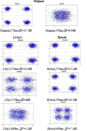 Figure 5 (a) 4-QAM Constellation diagrams of traditional CO-OFDM, L3by3and the proposed hybrid schemes at Different distance for 4-QAM
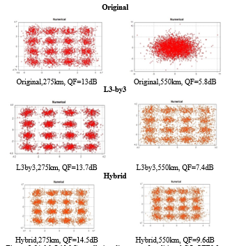 Figure 5 (b) 16-QAM Constellation diagrams of traditional CO-OFDM, L3by3and the proposed hybrid schemes at different distance for 4-QAM
Additionally, to examine the efficiency of the suggested Hybrid technique, the received power (RxP) and BER for the system with and without PAPR reduction techniques has been simulated. Figure (7) shows the results for the traditional system, the system with the L3by3 technique and the system with the proposed Hybrid technique at a distance of 550 km and launched laser power of 5 dBm. As shown in the figure, the best receiver sensitivity is obtained for the system with the Hybrid technique. Moreover, the figure demonstrates that the eye- opening of the system with the suggested combination technique is superior to the eye-opening in the case of using the L3by3 method or in the case of the primary system.
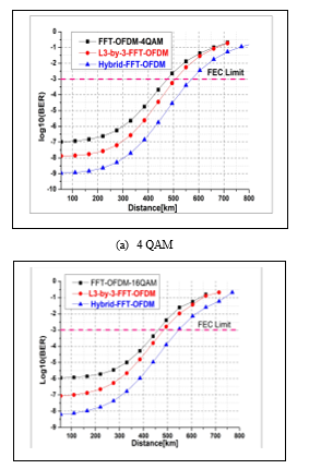 Figure 6 BER vs. distance
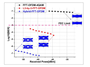 Figure 7 BER vs. received power at 550km for 4-QAM mapping order
Finally, Figure (8) shows the BER vs. OSNR for the traditional system, the system with the L3by3 method, and the system with suggested Hybrid reduction technique for PAPR at a distance of 550km and for 4-QAM and 16-QAM modulation orders. The results obtained show that when the value of the OSNR increases, the BER decreases.
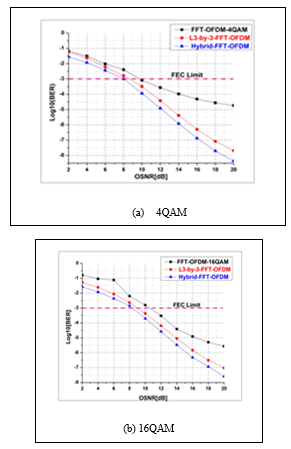 Figure 8 OSNR vs. BER for (a) 4-QAM-(left), (b) 16-QAM-(right) at 550km
Table (6) provides a performance summary based on the BER vs. OSNR results for the 16-QAM and 4-QAMTable.
Table.6 Received OSNR for 4-QAM and 16-QAM at a distance of 550km and BER of 10-3
| OSNR in dB at 550km | |||
| original | L3by3 | Hybrid | |
| 4 QAM | 10 | 8.5 | 8 |
| 16 QAM | 10.5 | 9 | 8.2 |
5. Conclusion
In this paper, an efficient and new hybrid method was proposed for PAPR reduction in CO-OFDM systems to lessen the impact of nonlinear effects and enhance the system performance. Both CO-OFDM with and without the proposed method were modeled using the VPI Transmission-Maker 9.5 and MATLAB software packages. The proposed scheme was shown to be an effective technique in reducing the PAPR. Furthermore, the scheme has low implementation complexity and no constraint on the system parameters because it does not need to send side information to the receiver. In addition, the results showed that the hybrid scheme can reduce the PAPR of the CO- OFDM by 4.35 dB and 4.5 dB for 4-QAM and 16-QAM mapping orders, respectively. The hybrid scheme also achieved better QF and BER performance compared to the L3by3 and traditional schemes.
- Shieh, W. and C. Athaudage, Coherent optical orthogonal frequency division multiplexing. Electronics Letters, 2006, vol. 42, issue10, p. 587-589.
- Shieh, W., H. Bao, and Y. Tang, Coherent optical OFDM: theory and design. Optics Express, 2008. 16(2): p. 841-859.
- Schmidt, B.J., A.J. Lowery, and J. Armstrong, Experimental demonstrations of electronic dispersion compensation for long-haul transmission using direct-detection optical OFDM. Journal of Lightwave Technology, 2008. 26(1): p. 196-203.
- Nazarathy, M., et al. Recent advances in coherent optical OFDM high-speed transmission. In PhotonicsGlobal@ Singapore, 2008. IPGC IEEE.
- Le, S., et al. Phase-conjugated subcarrier coding for fiber nonlinearity mitigation in CO-OFDM transmission. In Optical Communication (ECOC), 2014 European Conference on, IEEE.
- Goebel, B., et al. PAPR reduction techniques for coherent optical OFDM transmission. In Transparent Optical Networks, ICTON’09. 11th International Conference on. 2009. IEEE.
- Dung, H.V.T., et al. PAPR reduction using PTS with low computational complexity in coherent optical OFDM systems. In IEEE 2012 18th Asia-Pacific Conf. on Communications.
- Rishi, P. and S. Tamilselvi, Mitigation of Non-Linear Effects Using Non-Linear Transform in Dispersion- Managed Coherent Optical OFDM Systems. Journal of Computational and Theoretical Nanoscience, 2018. 15(2): p. 551-557.
- Wang, Z., et al. Performance analysis of different modulation schemes for coherent optical OFDM system. In Communications and Mobile Computing (CMC), 2010 International Conference on, IEEE.
- Nehra, M. and D. Kedia, Design of Optical I/Q Modulator Using Dual-drive Mach-Zehnder Modulators in Coherent Optical-OFDM System. Journal of Optical Communications, 2018. 39(2): p. 155-159.
- Gnanagurunathan, G. and F.A. Rahman. Comparing FBG and DCF as a dispersion in the long haul narrowband WDM systems. In Wireless and Optical Communications Networks, 2006 IFIP International Conference on,IEEE.
- Kharagpur, B.K., U. Wali, and S. Bidwai. Novel technique to reduce PAPR in OFDM systems by clipping and filtering. In Advances in Computing, Communications, and Informatics (ICACCI), International Conference on. 2013. IEEE.
- Chen, L., et al. PAPR reduction in optical OFDM systems using asymmetrically clipping and signal scrambling technique. In International Conference on Optical Instruments and Technology: Optoelectronic Devices and Optical Signal Processing. 2015. International Society for Optics and Photonics.
- Palanivelan, S.A.M., Modified Sliding Norm Transform based approach for PAPR optimization in OFDM Systems. Australian Journal of Basic and Applied Sciences, 2013: p. p. 10.
- Grigoryan, A.M., S. Dursun, and M.M. Grigoryan. Method of sliding norm transforms for peak-to-average power reduction in OFDM systems. In Industrial Electronics, 2006 IEEE International Symposium on. IEEE.
- Tong, Z.-r., Y.-n. Hu, and W.-h. Zhang, PAPR reduction in CO-OFDM systems using IPTS and modified clipping and filtering. Optoelectronics Letters, 2018. 14(3): p. 209-211.
- Xiao, J. et al., Hadamard transform combined with a companding transform technique for PAPR reduction in an optical direct-detection OFDM system. Journal of optical communications and networking, 2012. 4(10): p. 709-714.