A Joint Source Channel Decoding for Image Transmission
Volume 4, Issue 6, Page No 183-191, 2019
Author’s Name: Slim Chaoui1,4,a), Osama Ouda2,5, Chafaa Hamrouni3,6
View Affiliations
1College of Computer and Information Sciences, Dep. of Computer Engineering and Networks, Jouf University, Skaka, KSA.
2College of Computer and Information Sciences, Dep. of Computer Sciences, Jouf University, Skaka, KSA.
3Khurma University College, Dep. of Computer Sciences, Taif University, Khurma, KSA.
4Unit-Lab of Sciences of Electronics, Technologies of Information and Telecommunications, Sfax University, Sfax, Tunisia.
5Faculty of Computers and Information, Mansoura University, Mansoura, Egypt.
6REGIM-Lab, Sfax University, Sfax, Tunisia.
a)Author to whom correspondence should be addressed. E-mail: schaoui@ju.edu.sa
Adv. Sci. Technol. Eng. Syst. J. 4(6), 183-191 (2019); ![]() DOI: 10.25046/aj040623
DOI: 10.25046/aj040623
Keywords: Joint source-channel decoding, Arithmetic coding, Error resilience technique, Bit back-tracking, LDPC iterative decoding

Export Citations
In this paper, we present a joint source-channel decoding (JSCD) scheme for image transmission. The binary sequences, resulting from the compression of several number of image blocks using arithmetic coding (AC), are written line-wise in the so called read- matrix (RM). In succession, a systematic Low Density Parity Check (LDPC) encoding is applied to the sequence produced by the column-wise reading of the RM. The proposed approach to JSCD incorporates error-free AC-decoder information feedback and error- detection AC-decoder information feedback in each sub-sequence. An error resilience (ER) technique within AC provides whether the input sequence is correct or not and possibly identifies the corrupt segment. In case of error detection, the reliabilities of the bits in the AC decoder input stream are estimated involving the detection delay distribution of the erroneous symbols. This information is provided to the iterative LDPC decoder after a bit back-tracking stage. Experimental results show that the proposed JSCD scheme outperforms the separated source-channel model and reduces the number of decoding iterations.
Received: 23 August 2019, Accepted: 24 October 2019, Published Online: 09 December 2019
1. Introduction
This issue has motivated standards such as JPEG2000 to include certain error resilience (ER) techniques and gave rise for the development of joint source-channel techniques dedicated for the AC-encoded data [6, 7]. ER techniques were applied to identify the corrupt segment of the AC codestream. A common method for error detection in arithmetic coding was introduced in [8] where a non zero coding interval is reserved to a non coded symbol called forbidden symbol (FS). While decoding, if the FS is decoded, then an error in the received sequence is indicated. A study on the trade-off between the amount of added redundancy due to the FS and the amount of time required to detect an errors was proposed in [9]. In the works [10, 11], sequential decoding schemes were involved on binary trees and path pruning technique was applied relying on the FS error detection. In [11], Grangetto et al. have modeled arithmetic codes as state machines and a trellis representation for AC code with FS was used in conjunction with the maximum a-posteriori (MAP) decoding algorithm. The authors in [12] proposed a soft input soft output (SISO) arithmetic decoding where a FS-based ER technique was applied and a Chase-like algorithm was slightly modified to provide additional information on the reliability of the decoded bits. Practical implementations on the joint source-channel coding scheme with FS were studied in [13].
The iterative joint source-channel decoding (JSCD) was usually studied by making use of the channel observations and source information to improve the a-posteriori probabilities of each transmitted bit. This can be achieved through the repetitive update and adjustment of a-posteriori and extrinsic information on the one hand and source information on the other hand to achieve a better joint decoding error ratio. In [14], the extrinsic messages in the Turbo decoder are enlarged or reduced by means of the multiplication with a factor which depends on the channel conditions. In [15] channel adaptive plus or minis operations are made to modify the messages in LDPC decoder. Iterative JSCD based on bit flipping algorithms were proposed in [16, 12, 17] where a set of error patterns are generated by identifying the least reliable bits among the decoded sequence. Each test pattern is then checked for correctness by means of a verification code. In this concern, we propose a JSCD algorithm that takes advantage of the error detection capability provided by the FS-based ER technique in the AC decoder to improve the error correction capability of the iterative message passing algorithm (MPA) used for Low Density Parity Check (LDPC) decoding. The iterative decoding procedure offers a convenient way to make use of the source information feedback provided by the ER technique.
In this study, the arithmetic coded sequences of a certain number of image blocks are written line-wise in the so-called read-matrix (RM). In succession, the RM is read column-wise to form the information input sequence of the LDPC encoder. It is worth to note that block partitioning is a common process in the image compression standards, such as in JPEG2000 and H264, and is justified by the average entropy decrease of the image especially when block transformation are employed. For instance discrete the cosine transform is employed in JPEG-XR and HEVC and the discrete wavelet transformation in JPEG2000 and context-based compression algorithm, where the advantage of the correlation between neighboring image blocks is taken. With respect to error resilience, image partitioning is beneficial since error propagation may be prevented.
As a first contribution, the interplay between error detection position and bit reliabilities in the AC input code-stream is discussed and the error probability of each bit positioned before the detected error position is estimated. In this concern, a method for bit back-tracking is proposed which is of great importance in this work. It is worth to note that ACbased error detection is performed in symbol-takt whereas channel decoding is processed in bit-takt, and hence, the feedback information from the AC decoder is transformed in bit-takt.
A second contribution is associated with the proposed approach to JSCD and consists on the way how to involve the estimated bits reliabilities from the AC decoder in the iterative LDPC decoder. The purpose of this approach is to increase the reliabilities of the error-free AC decoded segments and to reduce them in possibly corrupted segments. This is reached by the conditional update of the messages during the iterative process with respect to the AC decoding results. Experimental results have shown that the proposed JSCD scheme outperforms the Tandem decoding and bit-flipping based JSCD schemes in terms of peak signal-to-noise ratio (PSNR), as well as accelerates the iterative MPA process.
The rest of this paper is organized as follows. Section 2 presents the proposed source-channel encoding scheme. In section 3 an overview over the AC is given and the FS-based ER technique is analyzed in terms of bit error probability versus error detection delay. The proposed JSCD scheme is outlined in Section 4. Simulation results are reported in Section 5. Section 6 concludes this paper.
2. Proposed source-channel coding scheme and transmission model
The proposed encoding scheme at the transmitter is depicted in Figure 1. Applying AC over NB equal size image blocks S1,··· ,SNB produces NB compressed sequences s1,··· ,sNB which are written line-wise into the K × L matrix, the socalled read-matrix (RM). The number of image blocks invited to be written in the RM is variable and depends on the RM size, on the image block size and on the AC compression rate for each image block. In order to restrict the zero filling, the block sequences have to be chosen in such a way that the number of not occupied positions in the RM becomes as small as possible. Set partitioning method is applied for this purpose. The sequence resulting from the column-wise reading of the RM is fed into a LDPC systematic encoder. Let c = (c1,··· ,cNc ) be the resulting LDPC codeword where Nc is the codeword length. The code bits of c are mapped into modulated sequence x. For simplicity, we consider a binary phase-shift keying (BPSK) modulation where the mth modulated symbol in x is given by xm = (1 − 2cm),1 ≤ m ≤ Nc. The mth symbol within the received sequence y can be expressed as
![]() where P is the received signal power at the receiver and nm is the instantaneous additive noise which is modelled as zeromean Gaussian random variable with variance σn2. In the sequel, we assume that P is unity. For a BPSK transmission the noise power is E{n2} = σn2 = BN0/2, where B is the bandwidth of the passband signal and N0/2 is the power spectral density per frequency unit of the white Gaussian noise. In addition, we note that the zero forced bit may be not transmitted when assuming the knowledge of the AC coded sequences lengths at the receiver which may re-establishes the zeros at the non-transmitted positions.
where P is the received signal power at the receiver and nm is the instantaneous additive noise which is modelled as zeromean Gaussian random variable with variance σn2. In the sequel, we assume that P is unity. For a BPSK transmission the noise power is E{n2} = σn2 = BN0/2, where B is the bandwidth of the passband signal and N0/2 is the power spectral density per frequency unit of the white Gaussian noise. In addition, we note that the zero forced bit may be not transmitted when assuming the knowledge of the AC coded sequences lengths at the receiver which may re-establishes the zeros at the non-transmitted positions.
For the purpose of the LDPC decoding, supplied by the MPA, the log-likelihood-ratio (LLR) of the mth estimated code bit, 1 ≤ m ≤ Nc, given the observation ym at the destination is
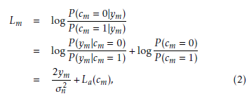 where La(cm) is the LLR corresponding to the a-priori information of the mth estimated code bit.
3. Overview of AC and ER techniques
Let Sb = (Sb,1,…,Sb,NS ) be the bth image block sequence of NS symbols from a finite alphabet A = {a1,··· , aNA} composed of NA symbols. Arithmetic coding requires the probability distribution of the input sequence. The interval [0,1) is divided into maximum NA sub-intervals, each with length equal to the occurrence probability of the alphabet symbols in the sequence Sb. The symbols Sb,1,··· ,Sb,NS are entered symbol by symbol to the arithmetic encoder. Let Low be the lower bound of the interval in which the symbol sequence so far is arranged and Length be the interval length, which is the product of the probabilities of all previous encoded symbols. Low and Length are initialized to 0 and 1, respectively. To encode a symbol from the sequence Sb, corresponding to the ith symbol in A, both Low and Length must be updated. Low X is refreshed by Low +Length fb,j and Length is replaced by j=1
Length fb,i, where fb,j is the probability of jth symbol in the alphabet A. After the entire sequence is arranged, it is uniquely specified by any value between Low and High = Low+Length. A number with the shortest binary representation in the interval will be transmitted. The most important advantage of AC is its optimality. AC is optimal in theory and is very nearly optimal in practice. In [18], it was shown that the required bit-size representing Sb is upper bounded by:
where j(Sb,s) corresponds to the position of the symbol Sb,s in A. The major drawback of such algorithm is that the encoding and decoding processes needs an infinite precision machine (values used for Low and High). This drawback was solved in [3], where the authors proposed the use of integer probabilities Fb,i = NS.fb,i and scaling techniques. The initial interval [0,1) was substituted by [0,W), where W = 2P r and P r ≥ 2 is the bit precision of the initial interval.
In order to generate incremental output while encoding, the authors in [3] proposed the scaling method where the size of the interval [Low,High) has to be doubled if one of the following conditions holds:
- E1 : 0 ≤ High < W/2:
- Low ← 2 · Low
- High ← 2 · High+1
- Ouput : 0 followed by Scale3 ones
- Scale3 ← 0
- E2 : W/2 ≤ Low < W:
- Low ← 2 · (Low − W/2)
- High ← 2 · (High − W/2)+1
- Ouput : 1 followed by Scale3 zeros
- Scale3 ← 0
- E3 : W/4 ≤ Low < W/2 ≤ High < 3W/4:
- Low ← 2 · (Low − W/4)
- High ← 2 · (High − W/4)+1
- Ouput : no output
- Scale3 ← Scale3+1
Note that Scale3 represents the number of the last E3 scaling done and is initialized to 0.
3.1 Proposed bit back-tracking within AC decoding with ER technique
The concept of ER technique is usually deployed with AC for the purpose of error detection which can help to reconstruct the corrupted segments of a code-stream. As far as JSCD is concerned, the error propagation properties of AC with the deployed ER technique is worthy studying. An accurate location of the bit errors is generally unachievable when making use of a simple ER technique. AC-based error detection is accomplished in symbol-takt and channel decoding is processed in bit-takt, and hence, the feedback information from the AC decoder should be obviously transformed in bit-takt. This is referred to as bit back-tracking.
We note that the decoding process is similar to the encoding process, and hence the AC decoder will either decode no source symbol or it will decode one or more source symbols for each input bit as described in the encoding process. For the purpose of bit back-tracking, we first define the AC extended encoding/decoding step as follows:
Definition: The AC extended encoding/decoding step is the succession of concluded AC encoding/decoding steps producing at least one output symbol/one output bit with Scale3 is zero or reset to zero.
We note that a concluded AC decoding step is settled when the new subinterval is not entirely within one of the intervals [0,1/2), [1/4,3/4) or [1/2,1). At the tth extended decoding step, the input bits located in the bit positions range φt produce output symbols located in the symbol positions range Φt. Up to now, let uˆ b,t and Sˆb,t denote the input bit sequence and the corresponding output symbol sequence at the tth extended decoding step, respectively. The main idea in the following subsections is that if at least one bit in uˆ b,t is erroneous, then at least one symbol in Sˆb,t is erroneous. For implementation issue a stack can be accessed, where the tth line contains the tuples (uˆ b,t,Sˆb,t). In order to elucidate the principle of AC extended encoding/decoding step and since encoding and decoding are similar, Table 1 illustrates an example of encoding a sequence S = abaac, where the symbols a, b and c have the occurrence frequencies 20, 10 and 20, respectively, cumulative counts {a,b,c} = {0,20,30,50} and W = 256. The first column is reserved for the extended encoding steps enumerator t.
For instance, at the third extended encoding step, aa and 010 constitute the input symbol sequence and the corresponding output bit sequence, respectively.
3.2 Forbidden symbol technique and error detection delay distribution
Let be the probability of the FS in the interval [0,1) which is never encoded. The amount of generated redundancy due to the FS is −log2(1 − ). Decoding the FS at the AC decoder is interpreted as an error detection.
Let ψb,p be the event that the FS is first appeared at the pth symbol position in the bth AC-decoded sequence and let Sˆb,p−d be the decoded symbol at the (p − d)th symbol position,
1 ≤ d ≤ p. The joint probability that the (p − d)th symbol is erroneous and the event ψb,p occurs can be expressed by
where Sp−d is the really transmitted symbol in the finite alphabet set and Ap is a normalization factor which depends on the position p. The probability given in (3) corresponds to the probability that a delay of d symbols is occurred before an error detection at the position p is performed. Thus, d is referred to as error detection delay.
Table 1: AC integer encoding of a sequence abaac with cumulative counts {a,b,c} = {0,20,30,50} and W = 256 showing the extended encoding steps.
| t | St | Low | High | ut | Scaling | Scale3 |
| – | – | 0 | 255 | – | – | 0 |
| 1 | a | 0 | 101 | 0
– |
E1 | 0 |
| 0 | 203 | – | 0 | |||
| 2 | b | 81 | 121 | 0
1 – |
E1 | 0 |
| 162 | 243 | E2 | 0 | |||
| 68 | 231 | – | 0 | |||
| 3 | a a | 68 | 132 | –
– 01 0 – |
E3 | 1 |
| 8 | 137 | – | 1 | |||
| 8 | 59 | E1 | 0 | |||
| 16 | 119 | E1 | 0 | |||
| 32 | 239 | – | 0 | |||
| 4 | c | 156 | 239 | 1
– |
E2 | 0 |
| 56 | 223 | – | 0 |
For simplicity, we assume that the occurrence probabilities of the symbols in the alphabet set are near to the forbidden symbol probability. Hence, (3) can be approximately given by the following truncated geometric distribution:
 The error detection delay distribution in the presence of a FB-based ER technique is investigated. A single bit error is arbitrarily introduced at the input sequence. The number of decoded symbols before decoding the FS is recorded. The probability density functions (PDF) of the error detection delay for two FS probability values, namely = 0.1 and = 0.2, are plotted in Figure 2. The finding reveals that the geometric distributions with parameters = 0.1 and = 0.2 fit the measured PDFs of the error detection delay.
3.3 Bit error probability estimation from the FSbased ER technique in the AC decoder
In this subsection we intend to determine the error probability of the AC decoder input bits before detecting the FS. Let Sˆb,t be the decoding result of the input bit sequence uˆ b,t at the tth extended decoding step and let φv and Φv be the ranges of input bit positions and output symbol positions at the tth extended decoding step, respectively. Within an extended decoding step, the AC encoding process is a one-toone relationship between the input symbol sequence and the output bit sequence. Accordingly, if the decoded sequence Sˆb,t is different from the correct one denoted by Sb,t, then the input bit sequence uˆ b,φt is certainly erroneous. Hence, the joint probability that the input sequence uˆ b,t is error prone and the event ψb,p occurs can be given by
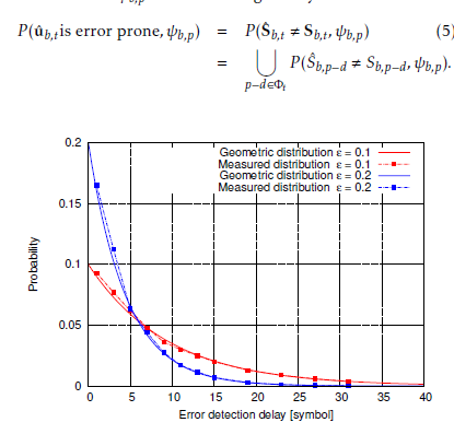 Figure 2: PDF of the error detection delay in the presence of a FS-based ER technique and comparison with the geometric distribution in (4) for = 0.1 and = 0.2.
Applying the approximation given in (4) and the pointcarre´ formula where all the multiplicative terms are neglected lead to the following approximation:
 Furthermore, the bit error probabilities in the bit range φt are assumed to be constant and denoted by Pe,t. This assumption reveals that the probability P (uˆ b,t is error prone, ψb,p) can be approximately given the following expression:
 where |φt| is the size of the bit range φt and ub,i is the correct bit at the input bit position i. From (6) and (7), the error probability of the bits in the input bit range φt can be approximately given by
 The bit error probability given in (8) is calculated within the AC decoding process so as to be involved in the JSCD as shown in the following section.
4. Iterative joint source-channel decoding
Error correction is usually done without taking into account any characteristics of the source data. This is attributable to the Shannon’s well-known source and channel coding separation theory [19]. However, many works in the last decades have shown that considering these two parts jointly can help to enhance the error control performance of the whole system [20, 21].
In the proposed JSCD scheme the information from the ER-based AC decoder, in form of error probabilities of the bits within the corrupted segment, is involved in the decoding process. The main purpose of this strategy is to increase the bit-wise reliabilities of the error-free AC decoded segments and to reduce them in possibly corrupted bit segments. The JSCD scheme is illustrated in Figure 3. The systematic nodes in the Tanner graph correspond to the input bits of the different AC decoders. Let qvr (0) denotes the message passing from the variable node v to the check node r at the lth round and represents the probability of cv = 0 given the channel observation yv, messages from all check nodes linked to the message node v expect the check node r (r0 ∈ Cv\r) and the check equation Ev involving the variable node v.
The corresponding log-likelihood ratio can be expressed by the following expression:
 where Lv is the LLR of the estimated code bit cˆv conditioned
(l−1) on its observed value yv as given in equation (2), Lr0v is the the LLR message passed from the check node r0 to the variable node v at the (l − 1)th round that the check equation in r0 is satisfied given the code bit cv and the messages from all variable nodes linked to check node r0 except the variable node v (v0 ∈ Vr\v). L(rl0−v1) is defined as follows [22]:
 The estimated hard code bit cˆv at the lth round is given by
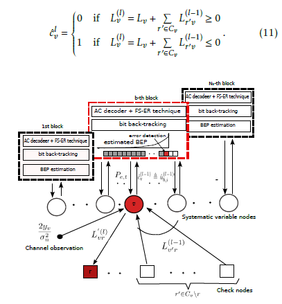 Figure 3: Joint Source-Channel Decoding scheme.
The correspondence between the code bit position v and the information bit position i in the bth input sequence is ensured according to the read write process in the RM. The AC decoder in the bth block performs error detection using the FS-based ER technique as described above. We distinguish two cases depending on the AC decoding results. The first case holds when AC error-free decoding is performed, in other words no FS is decoded. Let ψb,corr be the event when no error is detected while AC decoding of the bth input sequence at the (l − 1)th round. For these bits, the message passing from the variable node v to the check node r is modified according to the following expression:
 where A is a large positive value. These bits in correct decoding passes are now disclosed to the channel decoder, and they can support decoding other undetermined bits involved in the same check equations.
The second case holds when a FS at the position p at the (l − 1)th round is detected. Let ψb,p(l−1) denotes this event and let Eˆb,p denotes the estimated bit-end position corresponding to the detected FS position. At this stage a bit back-tracking effort muss be made to resolve the bit positions from the corresponding symbol position as described in subsection 3.1. The Bit error probability (BEP) of each information bit ub,i, at the positions i before Eˆb,p is estimated according to (8)
(l−1) and is denoted by Pe,t , where t is the extended decoding step corresponding to the bit position i, in other words i ∈ φt. No information about the input bits at positions after Eˆb,p
(l−1) is provided. The estimated Pe,t corresponds to bit error probability of the systematic variable node cv. The conventional message Llvr passing from the variable node v to the check node r at the lth iteration is given in (9). The updated message from the variable node v conditioned on the event (l−1) ψb,p , which returns due to the independence between the AC decoder input bits to the conditioning on the estimated (l−1) bit error probability Pe,t , is calculated as follows:
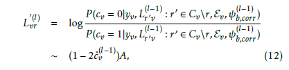
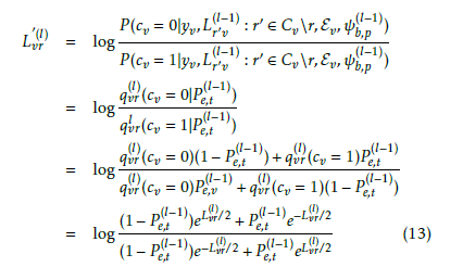 Applying the aforementioned change to all bit prior the error detection position could lead to weakening strong bits. To cope with this, it is convenient to limit the reliability change to the most unreliable bits. For this purpose, let Q be the random variable which characterizes the rank of ascending reliabilities Lv in (11) of erroneous bits . For example, Q= 5 means that the fifth least reliable bit is erroneous. Figure 4 shows the distribution of Q for the signal to noise ratio (SNR) levels per source information bit Eb/N0 = 2,3,4 and 5, and emphasizes that the rank of the most unreliable bits where errors occur is limited by a specific value denoted by QL that is considered as a parameter in the decoding process so as to limit the set of modified messages and hence to preserve strong bits. The value of QL will be fixed experimentally.
5. Simulation results
In this section we demonstrate the performance of the proposed JSCD scheme. Simulation studies are performed using a LDPC code of length Nc = 40000 and rate 1/2 with parameters (3,6). The outputs of the LDPC encoder are BPSK modulated and transmitted over the additive white Gaussian noise channel. We have tested our JSCD scheme using image block sizes of 16 × 16 and RM size of 200 × 100. The 512 × 512 Washsat image, initially coded at 8 bit per pixel (bpp), compressed at 5.52 bit per pixel (bpp), is considered as test image. Mean-squared error (MSE) values of decoded image are averaged over 1000 independent image transmissions at desired signal to noise ratio level. The average MSE is then converted to PSNR. The absolute value A of the LLRs in (12), corresponding to the segment of bit-streams that do not cause error detection, should be set to arbitrarily high values. In this work the value of A is set to 10. As a consequence, these bits are recognized as very reliable during the subsequent LDPC iteration.
First of all, the aforementioned value QL is examined. QL is the number of the most unreliable bits where errors occur and is dependent on the the received SNR level per source information bit Eb/N0 since the absolute value of LLRs become an increasingly significant reliability indicator as SNR increases. Figure 5 shows the PSNR evolution of the proposed JSCD scheme for Eb/N0 of 1, 2, 3 and 4 dB as a function of QL. The figure shows that the best PSNR performance is given for a certain QL value. For instance, for Eb/N0 = 3dB, the best QL value is 4. It is worth noting that the higher the SNR level is, the smaller QL is.
The performance of the proposed JSCD scheme is compared to that of the Tandem decoding scheme using soft input channel decoding and conventional arithmetic decoding. The PSNRs of the reconstructed images versus Eb/N0 are illustrated for the two schemes in Figure 6.
 Figure 4: Distribution of the rank of ascending reliabilities’ erroneous bits for Eb/N0 = 1,2,3 and 4 dB, .
It is worthy to remark that gains are obtained in terms of average PSNR throughout the SNR per source information bit range. In fact the proposed JSCD scheme exhibits PSNR gains of ∼ 4.5dB, ∼ 8dB and 4.5 dB over the Tandem decoding scheme at the SNRs 2dB, 3dB and 4dB, respectively. The proposed method adds AC decoding operations to each iteration, this can lead to a decoding complexity increase, which is obvious by JSCD subjects. This complexity rise could be balanced out by the suppression of the iteration number. Figure 7 illustrates the mean number of iterations needed for the proposed JSCD scheme as well as for the separated model.
It is obvious that the proposed JSCD system requires less decoder iterations, which means that the required decoding time can be reduced. The decoding iteration number gain can be achieved by as much as 13.8% to 22.18% in the range of Eb/N0 between 1 and 2 dB.
 Figure 5: Average PSNR evolution versus QL for Eb/N0 = 1,2,3 and 4 dB.
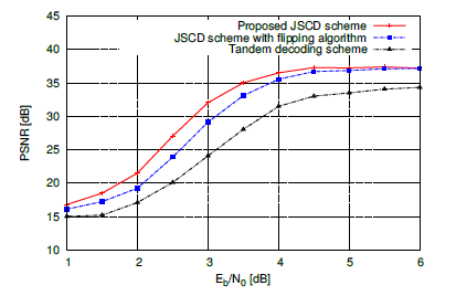 Figure 6: Average PSNR evolution versus Eb/N0 of the proposed JSCD scheme with = 0.2, Tandem decoding scheme and JSCD scheme with bit flipping algorithm.
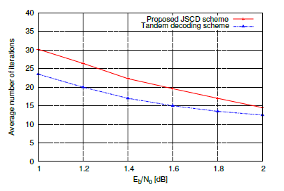 Figure 7: Average number of iterations of the proposed JSCD scheme and Tandem decoding scheme.
The results reported in the performed simulations show that the proposed JSCD outperforms standard separated scheme. On the other hand, the optimal choice of the system parameters remains an open issue; in fact, given a channel SNR, the error correction performance depends on the parameters such as FS probability , RM size, image block size. A large value of means more coding redundancy and assures a faster error detection. The value of is chosen as a trade-off between coding efficiency and error detection. One could look through simulations for a value achieving the best performance; since analytical performance bounds for the JSCD is very exhaustive. Figure 8 shows that the best JSCD performance is obtained with a value of = 0.2. In fact, the increase of from 0 to 0.2 gives a PSNR gain of ∼ 8dB for Eb/N0 = 3dB. Furthermore, a suitable choice of the RM size could lead to a well distribution of the strong bits over the whole LDPC decoder input sequence. Strong bits could be detected from the correct AC-decoded segments.
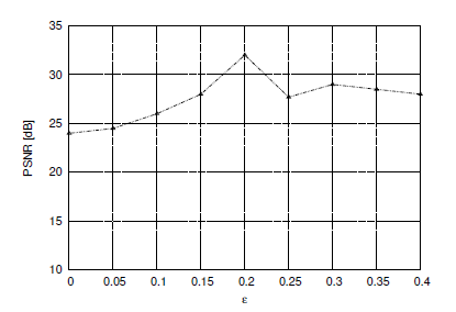 Figure 8: Average PSNR versus FS probability for Eb/N0 = 3dB.
As mentioned in the introduction, we compare the performance of the proposed JSCD scheme with that of the JSCD using the bit flipping algorithm. Such a bit-flipping idea has been used in various joint source-channel decoding approaches as in [16, 12, 17]. It consists on the flipping of the last Q unreliable bits. From these least reliable Q positions, one generate 2Q − 1 different error patterns. A candidate codeword is given by flipping the non-null bits in the error pattern. If no error detection is verified, the process stops. We note that no image partitioning is carried out during the bit flipping algorithm. A huge number of iterations could arise since 2Q error patterns must be tested for each image block. To cop with this, a single AC encoding operation was performed on the source message. In this work Q is set to 4 . The results reported in Figure 6 allow us to appreciate the gain offered up to a certain SNR.
6. Conclusion
In this paper, we proposed a JSCD scheme for image transmission. An error resilience technique was applied with AC and the interaction between error detection position and bit reliabilities in the AC input code-stream was discussed. The proposed approach to JSCD incorporates error-free AC-decoder information feedback and error-detection AC-decoder information feedback. In case of corrupted segments, bit backtracking is performed and bits reliabilities are estimated depending on the symbol error position. We have shown how the reliabilities of the bits in the AC decoder input stream are involved in the iterative MPA algorithm. The results show that the proposed scheme at low-to-medium SNRs outperforms the separate source-channel model by approximately 4 to 8 dB with respect to PSNR and reduces the average number of iterations.
Acknowledgment
The authors would like to thank the Deanship of Scientific Research at Jouf University for providing the financial support for publishing this work.
- S. Vembu, S. Verdu and Y. Steinberg, ”The source-channel separation theorem revisited” IEEE Transactions on Information Theory, 41(1), 44-54, 1995. DOI: 10.1109/18.370119
- J. Rissanen and GG. Langdon, ”Arithmetic coding” IBM Jour- nal of research and development, 23(2), 149-162, 1979. DOI: 10.1147/rd.232.0149
- IH. Witten, RM. Neal and JG. Cleary, ”Arithmetic coding for data com- pression” Communications of the ACM, 30(6), 520-540, 1987.
- A. Moffat, RM. Neal and IH. Witten, ”Arithmetic coding revisited” ACM Transactions on Information Systems (TOIS), 16(3), 256-294, 1998. DOI: 10.1145/290159.290162
- PG. Howard and JS. Vitter, Practical implementations of arithmetic coding In Image and text compression, Springer, Boston, MA, 1992.
- I. Moccagatta, S. Soudagar, J. Liang and H. Chen, ”Error-resilient cod- ing in JPEG-2000 and MPEG-4” IEEE Journal on Selected Areas in Communications, 18(6), 899-914, 2000. DOI: 10.1109/49.848245
- K. Kamaras, JPEG2000 image compression and error resilience for trans- mission over wireless channels, NAVAL POSTGRADUATE SCHOOL MONTEREY CA, 2002.
- C. Boyd, JG. Cleary, SA. Irvine, I. Rinsma-Melchert and IH. Witten, ”Integrating error detection into arithmetic coding” IEEE Transactions on Communications, 45(1), 1-3, 2000. DOI: 10.1109/26.554275
- J. Chou and K. Ramchandran, ”Arithmetic coding-based continuous error detection for efficient ARQ-based image transmission” IEEE Jour- nal on Selected Areas in Communications, 18(6), 861-867, 2000. DOI: 10.1109/49.848240
- BD. Pettijohn, MW. Hoffman and K. Sayood, ”Joint source/channel coding using arithmetic codes” IEEE Transactions on Communications, 49(5), 826-836, 2001. DOI: 10.1109/26.923806
- M. Grangetto, P. Cosman and G. Olmo, ”Joint source/channel coding and MAP decoding of arithmetic codes” IEEE Transactions on Commu- nications, 53(6), 1007-1016, 2005. DOI: 10.1109/TCOMM.2005.849690
- S. Zaibi, A. Zribi, R. Pyndiah and N. Aloui, ”Joint source/channel iterative arithmetic decoding with JPEG 2000 image transmission ap- plication” EURASIP Journal on Advances in Signal Processing, (1), 114, 2012. DOI: 10.1186/1687-6180-2012-114
- W. Zhang, F. Cen and F. Zhu F, Research on practical implementation of binary arithmetic coding with forbidden symbol for error resilience, In Frontiers in Computer Education, Springer, Berlin, Heidelberg, 2012.
- Z. Peng, YF. Huang and DJ. Costello, ”Turbo codes for image transmission-a joint channel and source decoding approach” IEEE Jour- nal on Selected Areas in Communications, 18(6), 868-879, 2000. DOI:
10.1109/49.848241 - W. Liu and DG. Daut, ”Progressive image transmission based on joint source-channel decoding using adaptive sum-product algorithm” Journal on Image and Video Processing, (1), 18-18, 2007. DOI: 10.1155/2007/69805
- B. Zheng and S. Gao, ”A soft-output error control method for wire- less video transmission” in 2016 8th IEEE International Conference on Communication Software and Networks (ICCSN), Jun 2016. DOI: 10.1109/ICCSN.2016.7586585
- T. Tonnellier, C. Leroux, B. Le Gal, B. Gadat, C. Jego C and N. Van Wambeke, ”Lowering the error floor of turbo codes with CRC verifica- tion” IEEE Wireless Communications Letters, 5(4), 404-407, 2016. DOI: 10.1109/LWC.2016.2571283
- PG. Howard and JS. Vitter, ”Arithmetic coding for data compression”Proceedings of the IEEE, 82(6), 857-865, 1994. DOI: 10.1109/5.286189
- CE. Shannon, ”A mathematical theory of communication” Bell system technical journal, 27(3), 379-423, 1948. https://doi.org/10.1002/j.1538- 7305.1948.tb01338.x
- JL. Massey, Joint source and channel coding, MASSACHUSETTS INST OF TECH CAMBRIDGE ELECTRONIC SYSTEMS LAB, Sep 1977.
- J. Hagenauer, ”Source-controlled channel decoding” IEEE Transactions on Communications, 43(9), 2449-2457, 1995. DOI: 10.1109/26.412719
- A. Shokrollahi, LDPC codes: An introduction Digital Fountain, Inc., Tech. Rep, 2003.
Citations by Dimensions
Citations by PlumX
Google Scholar
Scopus
Crossref Citations
- Maheswari K, Padmaja Nimmagadda, "Advancements in Wireless Video Communication Optimization: A Comprehensive Comparison." In 2023 International Conference on Next Generation Electronics (NEleX), pp. 1, 2023.
- Amaad Khalil, Nasru minallah, Muhammad Asfandyar Awan, Hameed Ullah Khan, Atif Sardar Khan, Atiq ur Rehman, Farman Ullah, "On the Performance of Wireless Video Communication Using Iterative Joint Source Channel Decoding and Transmitter Diversity Gain Technique." Wireless Communications and Mobile Computing, vol. 2020, no. , pp. 1, 2020.
- Maheswari K, Padmaja Nimmagadda, "Error resilient wireless video transmission via parallel processing using puncturing rule enabled coding and decoding." e-Prime - Advances in Electrical Engineering, Electronics and Energy, vol. 6, no. , pp. 100324, 2023.
- Hassan Y. El-Arsh Mohamed, Amr Abdelaziz, Ahmed Elliethy, Hussein A. Aly, Alaa Eldin Rohiem Shehata, "Joint Compression-Encryption Technique Based On Arithmetic Coding for JPEG Images." In 2023 5th Novel Intelligent and Leading Emerging Sciences Conference (NILES), pp. 63, 2023.
- Ishtiaque Ahmed, Gulzar Ahmad, Nasru Minallah, Jaroslav Frnda, Amaad Khalil, Tariqullah Jan, Hameed Ullah Khan, "Enhancing reliability with MIMO aided dual iterations for mobile video transmission system." Wireless Networks, vol. 31, no. 3, pp. 2257, 2025.
No. of Downloads Per Month
No. of Downloads Per Country