A Proposal of TCP Fairness Control Method for Two-Host Concurrent Communications in Elastic WLAN System Using Raspberry Pi Access-Point
 , Minoru Kuribayashi 1, Kwenga Ismael Munene 1, Md. Manowarul Islam 1, Wen-Chung Kao 2
Adv. Sci. Technol. Eng. Syst. J. 4(6), 10–18 (2019);
 DOI: 10.25046/aj040602
The IEEE802.11n based Wireless Local Area Networks (WLANs) have been extensively deployed due to the flexible coverage, the easy installation, and the lower cost. To reduce the energy consumption while increasing the performance, the elastic WLAN system has been studied, such that it can dynamically change the network configuration according to traffic demands. As well, the test-bed has been implemented and for the access point (AP), Raspberry Pi is used as a portable, energy conservation, and powerful computing device. Our test-bed measurements with a single AP of two concurrently communicating hosts found the unfairness throughput results, due to the TCP windows size became different among them. To overcome this drawback, in this paper, we propose the TCP fairness control method for two concurrently communicating hosts in the elastic WLAN system. By controlling the delay at the packet transmission, the slower host will obtain more transmission opportunities than a faster host. The delay is firstly calculated by the received signal strength (RSS) from every host. After that, the delay is controlled by the PI controller to balance the both throughputs. For evaluations, we execute the proposal in the elastic WLAN system test-bed and carry out extensive measurements, where the TCP throughput fairness is achieved.
1. Introduction
In WLAN, hosts are mostly non-uniformly located [3], and communicating hosts or traffics tends to fluctuate unpredictably [4, 5] according on the period time and in a week. Furthermore, conditions of network devices and communication links may be influenced by certain factors, such as device failures, power shortages, weather changes, or bandwidth controlled by their authorities [6].
Under such circumstances, we have examined the elastic WLAN system that dynamically optimizes the network configuration based on demands in a network, to reduce the energy consumption during Raspberry Pi is a card-size, single-board computer that can solve a variety of practical problems requiring computation or networking abilities [9], additionally, it is equipped with the built-in wireless network interface (NIC) supporting IEEE802.11n.
In WLAN, the fairness of the throughput quality among the hosts is necessary to ensure the fair quality of services (QoS) for the users [10]. Hence, fairness problems in WLAN have been explored extensively [11]-[14]. Since a large number of network applications in the Internet adopt the transmission control protocol (TCP), the TCP fairness is exceedingly critical.
Nevertheless, our preliminary measurements using the elastic
WLAN system test-bed have revealed that the TCP throughput is not superior among the two concurrently communicating hosts associated with the same AP when they are located at different positions from the AP. It is assumed that this unfairness was caused by differences in the TCP window size and the modulation and coding scheme (MCS) among them. Therefore, the packet transmission interval of the farthest host hereafter becomes longer, and the interval for the nearest host becomes shorter.
In this paper, we propose the TCP fairness control method for two concurrently communicating hosts in the elastic WLAN system. The transmission delay is implemented at the AP in the packet transmission to the nearer host. After that, it can be predicted that the nearer host will decrease the throughput, and the farther host will enhance it by obtaining more transmission opportunities. This delay is firstly calculated by the received signal strength (RSS) from hosts. After that, it is dynamically controlled using the PI controller [15] to achieve the desired throughput fairness.
For performance evaluations, the proposal is implemented in Raspberry Pi AP and conduct experiments to verify the effectiveness using the test-bed with static and dynamic hosts in different network fields.
The remainder of this paper is structured as follows: Section 2 shows the preliminaries of the works. Section 3 demonstrates the TCP fairness control method. Section 4 and 5 evaluates the proposal through test-bed experiments. Section 6 discusses the observation result. Finally, Section 7 concludes this paper with future works.
2. Preliminaries
In this section, we introduce our preliminary work to relate this paper.
2.1 Elastic WLAN System
The elastic WLAN system has been designed and developed to control and manage the number of active APs in the network field according to the traffic demand. Figure 1 shows the test-bed topology of the system.
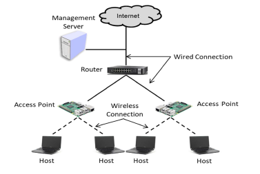 Figure 1: Elastic WLAN system topology.
The server has the administrative access to all the network devices including the APs, so that it can control them by executing the active AP configuration algorithm by the following procedure:
- The server examines the network devices and collects the necessary information for the active AP configuration algorithm.
- Then, it executes the active AP configuration algorithm and the output of the algorithm contains the minimum number of APs, the AP-host associations, and the allocated channels.
- Finally, it implements the output of the previous step by deactivating or activating the selected APs, changing the requisite host associations, and allocating the channels.
2.2 Software AP Configuration
In this paper, we adopt Raspberry Pi 3, that uses Raspbian OS, Broadcom BCM2837 SOC, LPDDR2-900MHz 1GB SDRAM, 10/100Mbps Ethernet, IEEE 802.11b/g/n wireless NIC, Bluetooth 4.1 classics/low energy, and 400MHz video core IV GPU [9]. The procedure to configure the Raspberry Pi 3 device to function as a Wi-Fi AP is as follows:
- First, hostapd is installed by the command as follows:
- Then, the /etc/hostapd/conf configuration file is modified with the SSID and PASSWORD. An example of the configuration file is provided as follows:
- Next, the absolute path is set to run hostapd while booting the system using the following command:
- The static IP address in the em wlan0 interface is assigned by modifying file /etc/network/interfaces as follows:
- Finally, install the DHCP server for assigning the dynamic IP addresses to the hosts.
2.3 Jain’s Fairness Index
There are various definitions have been proposed for the fairness index. Among them, Jain’s fairness index [16] is the representative one for the TCP fairness:
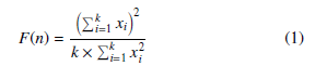 Here k represents the total number of connections and xi does the throughput for the i-th connection. When all the connections receive the same throughput, this fairness index becomes 1, which means that all the connections are 100% fair. As the disparity increases, the fairness will decrease.
2.4 Unfairness Problem in Concurrent Communication
We initially measured the TCP fairness among concurrently communicating multiple links with a single AP using the elastic WLAN system test-bed with the various distances between host. We conducted the experiments in Asahi Riverbed as an outdoor environment. By using Homedale [17], it is confirmed that all interfering signals have been removed from this environment.
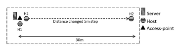 Figure 2: Outdoor measurement field.
Figure 2 indicates the locations of the AP and two hosts in the measurements. The position of the host H2 is changed from 0m to 30m with the 5m step while the position of H1 is fixed at the 0m distance from the AP. Then, the throughput and RSS are measured at both H1 and H2. For each measurement, iperf software [18] is used to generate the traffic from both hosts at the same time to the AP.
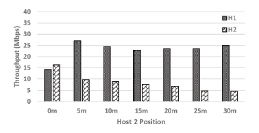 Figure 3: Throughput at different locations for H2.
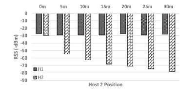 Figure 4: RSS at different locations for H2.
Figure 3 indicates throughput measurement results, which are similar at both hosts when the H2 distance from the AP is 0m. However, as the H2 distance increases, the throughput difference will increase accordingly. The throughput of H2 decrease due to the smaller RSS (receiving signal strength). Nevertheless, the throughput of H1 will increase, although RSS at H1 is constant as shown in Figure 4. This is considered as an inspiring result, that is to say, it seems that the nearer host to the AP will take higher transmission opportunities than the further host, which leads to the unfairness of the TCP throughput performance among them.
3. Proposal of TCP Fairness Control Method
In the section, we describe the proposal of the TCP fairness control method in the concurrent TCP communications of two hosts with a single AP.
3.1 Overview
Our test-bed experiments results unfold that the two-host concurrently communicating with a single AP causes the unfairness in the throughput performance, due to the different packet transmission intervals among them. Figure 5a demonstrates the packet transmission intervals between the near and far hosts. The throughput unfairness happens by the differences in the MCS and TCP window size. For the near host, the TCP windows size will be larger because of faster MCS compare to the far host. Then, it will occupy the far larger bandwidth during the communications compare to the other host, thus the packet transmission interval between them increases.
To overcome the issue, the transmission delay is intentionally introduced in the packet transmission of the AP to the near host. By minimizing the transmission bandwidth of the link with the near host, it will give more transmission bandwidth to the link to the far host. To achieve the throughput fairness, this delay should be controlled such that the intervals of packet transmission become equal, as shown in Figure 5b.
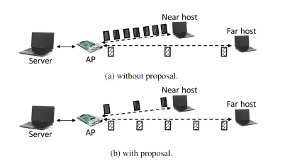 Figure 5: Background of TCP fairness control method.
The transmission delay is initially calculated by collecting the RSS at the AP from the near host and from the far host, because the measured RSS influences the MCS. After that, the transmission delay is controlled dynamically by the PI control during communications to attain the fairness accurately in the network.
3.2 Initial Delay Calculation
The initial transmission delay D(0) is computed from the difference of the measured RSS between the two hosts:
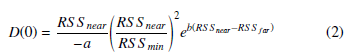 The parameter values are obtained from our experimental results in [19]. Where, RSS min = −88dBm from [20] is considered as the minimum RSS that a host can receive packets successfully from a Raspberry Pi AP, RSS near does the measured RSS at the AP from the near host, RSS far does the measured RSS from the far host, and the constant parameter a and b are needed to be set depending on the environment. Here, a = 8, b = 0.15 for the outdoor field, and a = 9, b = 0.17 for the indoor field are used, respectively. If the RSS is smaller than RSS min, the host cannot receive any packet successfully.
3.3 Dynamic Delay Optimization by PI Controller
In this stage, to achieve the target fairness index, the delay is dynamically controlled by the PI controller [15]. The delay is optimized dynamically as follows:
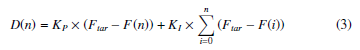 Here, D(n) represents the delay, F(n) does the measured fairness index at the n-th time-step, and KP and KI does the gain for the P control and for the I control, respectively. Where, Ftar = 0.97, KP = 3, and KI = 0.8 are used. It is noted that the PI controller periodically changes the delay with the 20sec time-step. In the system implementation, the equation in (3) is modified as follows:
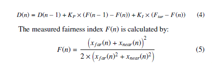 where xfar(n) and xnear(n) represent the measured throughput of the far host and that of the near host at the n-th time-step, respectively.
3.4 Test-bed Implementation
Here, we show the implementation of our proposal in the elastic WLAN system test-bed.
3.4.1 RSS Measurement
We collect the measured RSS of every host by using the command as follows at the AP:
where the AP does not require to access to the host. Since the RSS continually fluctuates, RSS is measured for 30 seconds, and their average is used in Eq. (2).
3.4.2 Transmission Delay Application
Next, the transmission delay is applied to the packet transmission from the AP to the nearest host by the following procedure:
- Remove any delay previously assigned at the interface wlan0:
- Assign each delay at the packet transmission from the AP to every host, namely d1 and d2:
- Enforce every delay to the packet transmission to the nearest host and the far host that is specified by the IP address:
Here, the IP address of each host is automatically set by the following program:
Linux commands for near host detection
#/bin/bash
# for check total connected hosts 01: sudo hostapd_cli all_sta | grep “dot11RSNAStatsSTAAddress=” while [ “$i” -le “$totalConnectedHost” ] do
# for collecting the IP address
02: arp -a | grep $mac
# merge MACAddress, IP Address and RSS 03: echo $mac” ” $ip” ” $rss >> data.tmp done
# sort descending data.tmp by rss value
04: sudo sort -nrk 3 data.tmp> sort.tmp
# 1st line in sort.tmp is the nearest host
3.4.3 Dynamic Delay Optimization
Firstly, the initial delay is obtained to the nearest host from the server by the following step:
- Explore the IP and MAC addresses of the connected hosts.
- Request the AP to measure the RSS of the hosts for 30sec and send back to the server.
- Find the average of the measured RSS.
- Compute D(0) by Eq. (2).
- Assign D(0) as the transmission delay to the nearest host.
Then, the delay is optimized dynamically by the following steps at every 20sec:
- Measure the throughput of the hosts for 20sec using iperf.
- Compute F(n) by Eq. (5).
- Update D(n) by Eq. (4).
- Set D(n) as the transmission delay to the faster host at the AP.
4. Evaluations with Static Hosts
In this section, we evaluate the proposal through experiments when all the hosts are stationary.
4.1 Experiment Setup
In our experiments, we generate TCP traffic from two concurrently communicating hosts to the server to measure the throughput. Figure 6 illustrates the network setup of the server, the AP, and the hosts.
The server is connected with a 100Mbps wired connection to the
AP, and the host is connected to the AP through the IEEE802.11n 2.4Ghz wireless link. The traffic is generated from the host to the server using iperf. The buffer size and the TCP window size are set to 8KB and 477KB, respectively.
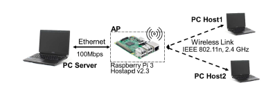 Figure 6: TCP link configuration.
Table 1 reveals software and hardware specifications for our experiments. Three laptop PCs are used for the two client hosts and the one server, and one Raspberry Pi is configured for the AP operating on channel 13.
Table 1: Hardware and software specifications.
| server and hosts | |
| type | R731/B, Toshiba Dynabook |
| operating system | Linux (Ubuntu 14) |
| RAM | 4GB DDR3-1333MHz |
| processor | Intel Core i5-2520M, 2.5Ghz |
| software | Iperf 2.0.5 |
| access point | |
| type | Raspberry Pi 3 |
| operating system | Linux (Raspbian) |
| RAM | LPDDR2 900MHz 1GB |
| processor | BCM2837 1.2Ghz, Broadcom , |
| NIC | BCM43438, Broadcom |
| software | hostapd |
4.2 Experiments in Outdoor Field
First, the experimental results are provided in the outdoor field.
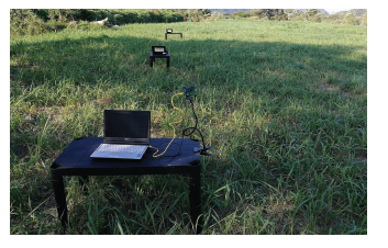 Figure 7: Outdoor field.
4.2.1 Experiment Field
As the outdoor field, experiments are conducted in Asahi Riverbed shown in Figure 7. There is no interfering signal, which is confirmed by using Homedale. The height of the AP and the hosts are
135cm and 70cm, respectively. During experiments, the distance of H1 from the AP is set 0m, 5m, 10m, and 15m. Then, for each H1 distance, H2 is located at 0m, 5m, 10m, 15m, 20m, 25m, and 30m from the AP. Finally, the throughput experiments are carried out in three methods: 1) without proposal, 2) initial delay only, and 3) proposal.
4.2.2 Throughput Results
Figure 8 illustrates the throughput results of the two hosts for 1) without proposal, where the unfairness appears between H1 and H2. Figure 9 shows the results for 2) initial delay only, where the fairness of each host is improved. Figure 10 shows the results for 3) proposal, where the fairness is achieved at any position by implementing our proposal. Figure 11 shows the overall throughput comparison at each H1 location. Nevertheless, with the proposal, the overall throughput has been reduced by 2.78% on average.
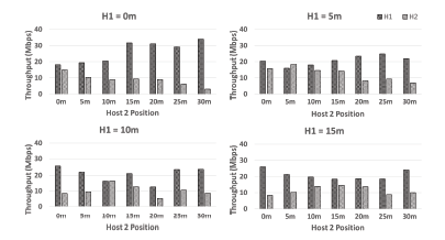 Figure 8: Results of throughput in outdoor field for 1) without proposal.
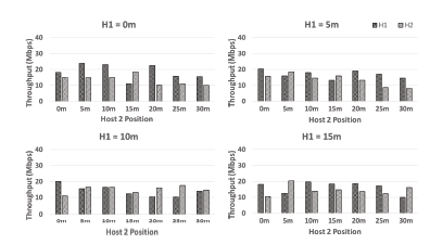 Figure 9: Results of throughput in outdoor field for 2) initial delay only.
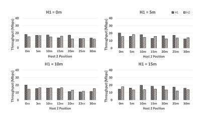 Figure 10: Results of throughput in outdoor field for 3) proposal.
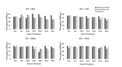 Figure 11: Results of overall throughput in outdoor field.
4.2.3 Fairness Index Results
Figure 12 demonstrates the Jain’s fairness index result. From the Eq. (1) known 1 is the finest fairness index. For 1) without proposal, any result appears to be lower than 1. Nevertheless, for 3) proposal, the fairness index will generally become close to 1. It is found that the proposal presents better achievement in the fairness index than the comparisons.
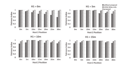 Figure 12: Observed TCP fairness index in outdoor field.
4.3 Experiments in Indoor Field
Second, experimental results in the indoor field are provided.
4.3.1 Experiments in Two-room Case
The two rooms in the 3rd floor of Engineering Building #2 at Okayama University are used in the experiment. Figure 13 illustrates the layout of this field.
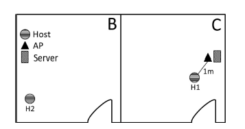 Figure 13: Experimet field for two-room case.
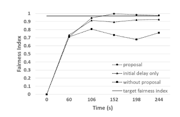 Figure 14: TCP fairness index results in indoor field for two-room case.
Figure 14 shows the fairness index results. The system collected the RSS and other necessary data during the first 60sec to measure the throughput. Next, it was observed that the fairness index for each method is about 0.7. Then after 130sec, fairness is achieved for 3) proposal. Conversely, 1) without proposal and 2) initial delay only could not achieve it.
4.3.2 Experiments in Four-room Case
Then, the four rooms on the same floor are used in the experiment. Figure 15 illustrates the layout of this building that has a complex structure of multiple rooms and walls. This figure shows the position of the AP (triangle), the server (square), and the possible position of the hosts (circle). Here, the AP and the host are configured similarly to the outdoor field. H1 is located at A1 and B2 in the indoor field. Then, for each H1 position, H2 is moved from A1 to D4, respectively.
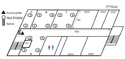 Figure 15: Indoor field.
Figure 16 illustrates the throughput results of the two hosts for 1) without proposal. The unfairness appears between H1 and H2. Figure 17 shows the results for 2) initial delay only, where the fairness is slightly improved. Figure 18 shows the results for 3) proposal, where the fairness is achieved by the proposal. Figure 19 shows the overall throughput comparison at each H1 location. However, by applying the proposal, the overall throughput has diminished by 14.83% on average.
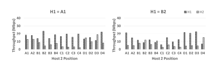 Figure 16: Results of throughput in indoor field for 1) without proposal.
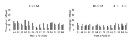 Figure 17: Results of throughput in indoor field for 2) initial delay only.
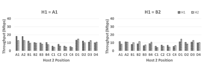 Figure 18: Results of throughput in indoor field for 3) proposal.
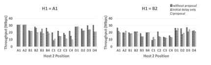 Figure 19: Results of overall throughput in indoor field.
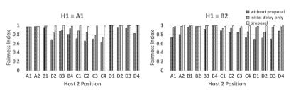 Figure 20: TCP fairness index results in indoor field for four-room case.
5. Evaluations with Dynamic Hosts
Next, we evaluate the TCP fairness control method through experiments when one host is dynamically connected and disconnected to the AP.
5.1 Experiment Setup
The topology in Figure 13 and the devices/software in Table 1 are used in this experiment. Figure 21 indicates the 20min scenario of dynamically connecting and disconnecting one host. Initially, H1 is connected to the AP. At 0min, iperf TCP traffics are generated for 5min. At 5min, H2 is connected to the AP, and the proposed method is started to run manually. Then, the server will collect the RSS and measure the throughput at H1 and H2. Afterward, at 10min, H2 is disconnected from the AP, and the server measures the throughput of H1. Lastly, at 15min, both H1 and H2 are connected.
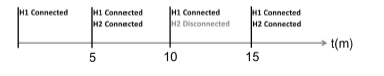 Figure 21: Time scenario for dynamically connecting/disconnecting host.
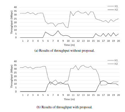 Figure 22: Individual throughput of H1 and H2 with dynamic hosts.
5.2 Results
Figure 22 shows the individual throughput for H1 and H2. At 0min, where only H1 is connected to the AP, the individual throughput is about 33Mbps. Next, at 5min, where both hosts are connected, the individual throughput of H1 decreases due to the concurrent communication. Here, with proposal can achieve the throughput fairness between two hosts, where it is around 12Mbps for each host. On the other hand, without proposal cannot achieve it. Thus, our proposal has proved to reach the throughput fairness between two concurrently communicating hosts with a single AP, even if a host is continually connected and disconnected to the AP.
6. Discussions
In this section, we discuss the summaries of experiment results in the previous sections and future works.
The TCP fairness control method is proposed in this paper so that any host communicating with the same AP can enjoy the similar throughput regardless of the relative position from the AP. This service fairness is important in designing and managing a local-area network, including the wired and wireless LANs. To verify the effectiveness of the proposal, evaluations with static and dynamic hosts are conducted using real devices.
First, the experiment results with static hosts in Section 4 show the improvement of the fairness index from 0.85 to 0.98 on average by the proposal, whereas the average overall throughput is dropped by 2.78% in outdoor fields and by 14.83% in indoor fields on average. Since the possible throughput of WLAN is increasing rapidly due to the advancements of wireless communication technologies, these drops of the overall throughput are acceptable.
Second, the experiment results with dynamic hosts in Section 5 show that the fairness index is improved from 0.69 to 0.97 on average by the proposal, whereas the average overall throughput is dropped by 3.21% on average. This small drop of the overall throughput is acceptable.
From these results, it is confirmed that the TCP fairness control method is practical and useful in achieving the throughput fairness among the two concurrently communicating hosts with the AP.
The weakness of the proposal is the use of the throughput measurement software (iperf in this paper). Every host in WLAN must install the client software, which can be an obstacle for practical use. In future works, we will investigate a method of estimating the throughput without installing this software at a host.
Besides, the proposed method is based on empirical works with a lot of experiments using real devices. The theoretical analysis of two-host concurrent communications and the model formulation for simulations will be also in future works. This model should accurately estimate the throughput for a given transmission delay at the packet transmission from the AP to a host when two hosts are concurrently communicating with the single AP.
7. Conclusion
This paper proposed the TCP fairness control method for two concurrently communicating hosts in the elastic WLAN system where the delay is implemented in the packet transmission of the faster host. Initially, the delay is estimated by collecting the RSS of the hosts at the AP. Then, it is dynamically controlled using the PI controller to achieve throughput fairness between the hosts. Extensive experiments with static and dynamic hosts confirmed the effectiveness of the proposal. In future works, the proposal will be extended to three or more concurrently communicating hosts and carry out experiments in different topologies and network fields.
Acknowledgments
This work is partially supported by JSPS KAKENHI (16K00127).
- R. W. Sudibyo, N. Funabiki, M. Kuribayashi, K. I. Munene, M. M. Islam, and W.-C. Kao, “A TCP fairness control method for two-host concurrent commu- nications in elastic WLAN system using Raspberry Pi access-point,” in Proc. 2nd Int. Conf. Commun. Eng. Tech. (ICCET 2019), pp. 76-80, 2019.
- B. P. Crow, I. Widjaja, J. G. Kim, and P. T. Sakai, “IEEE 802.11 wireless local area networks,” IEEE Commun. Mag., vol. 35, no. 9, pp. 116-126, Sept. 1997.
- K. Mittal, E. M. Belding, and S. Suri, “A game-theoretic analysis of wireless access point selection by mobile users,” Comput. Commun., vol. 31, no. 10, pp. 2049-2062, Jan. 2008.
- M. Balazinska and P. Castro, “Characterizing mobility and network usage in a corporate wireless local-area network,” in Proc. Int. Conf. Mob. Syst. Appl. Ser., pp. 303-316, 2003.
- D. Kotz and K. Essien, “Analysis of a campus-wide wireless network,” Wirel. Netw., vol. 11, no. 1-2, pp. 115-133, Jan. 2005.
- F. Nadeem, E. Leitgeb, M. S. Awan, and S. Chessa, “Comparing the life time of terrestrial wireless sensor networks by employing hybrid FSO/RF and only RF access networks,” in Proc. Int. Conf. Wirel. Mob. Commun., pp. 134-139, 2009.
- M. S. A. Mamun, M. E. Islam, N. Funabiki, M. Kuribayashi, and I-W. Lai, “An active access-point configuration algorithm for elastic wireless local-area network system using heterogeneous devices,” Int. J. Network. Comput., vol. 6, no. 2, pp. 395-419, July 2016.
- M. S. A. Mamun, N. Funabiki, M. E. Islam, and W.-C. Kao, “A channel as- signment extension of active access-point configuration algorithm for elastic WLAN system and its implementation using Raspberry Pi,” Int. J. Network. Comput., vol. 7, no. 2, pp. 248-270, July 2017.
- Raspberry Pi, “The official website of the Raspberry Pi project,” http://raspberry.org. Accessed 19 Feb., 2019.
- S. Pilosof, R. Ramjee, D. Raz, Y. Shavitt, and P. Sinha, “Understanding TCP fairness over wireless LAN,” in Proc. IEEE INFOCOM, April 2003.
- T. Nandagopal, T. Kim, X. Gao, and V. Bharghavan, “Achieving MAC layer fairness in wireless packet networks,” in Proc. ACM Mobicom, Aug. 2000.
- N. Blefari-melazzi, A. Detti, A. Ordine, and S. Salsano, “A mechanism to enforce TCP fairness in 802.11 wireless LANs and its performance evaluation in a real test-bed,” in Proc. World. Wirel. Mob. Multi. Net., pp. 1-7, 2007.
- B. A. H. S. Abeysekera, T. Matsuda, and T. Takine, “Dynamic contention window control mechanism to achieve fairness between uplink and downlink flows in IEEE 802.11 wireless LANs,” IEEE Trans. Wirel. Commun., vol. 7, no. 9, pp. 3517-3525, 2008.
- E. Park, D. Kim, H. Kim, and C. Choi, “A cross-layer approach for per-station fairness in TCP over WLANs,” IEEE Trans. Mob. Comput. vol. 7, no. 7, pp. 898-911, 2008.
- K. Astrom and T. Hagglund, “PID controller: theory, design, and tuning, 2nd Ed.”, Inst. Socie. America, 1995.
- R. Jain, D. Chiu, and W. Hawe, “A quantitative measure of fairness and dis- crimination for resource allocation in shared computer system,” East. Res. Lab. (DEC), vol. 38, 1984.
- Software Verzeichnis development, Homedale WLAN Monitor, http://www. the-sz.com/products/homedale. Accessed 19 Feb., 2019.
- Iperf, The ultimate speed test tool for TCP, UDP and SCTP, https://iperf. fr/. Accessed 27 Feb., 2019.
- R. W. Sudibyo, N. Funabiki, M. Kuribayashi, K. I. Munene, M. M. Islam, and W.-C. Kao, “A TCP fairness control method for concurrent communications in elastic WLAN system using Raspberry Pi access-point,” IEICE Tech. Rep., NS2018-175, pp. 96-100, Dec. 2018.
- Cypress, “CYW43438, Single-Chip IEEE 802.11 b/g/n MAC/Baseband/Radio with Integrated Bluetooth 4.2,” 2016.