
Transmission Line Restoration Using ERS Structure
Volume 4, Issue 5, Page No 394-400, 2019
Author’s Name: Sushri Mukherjee1,a), Sumana Chattaraj1, Md. Irfan Khan1, Dharmbir Prasad2, Pradip Barua1, Harish Agarwal1
View Affiliations
1Supreme & Co. Pvt. Ltd., 700020, West Bengal, India
2Asansol Engineering College, 713305, West Bengal, India
a)Author to whom correspondence should be addressed. E-mail: manel.jomaa@enit.utm.tn
Adv. Sci. Technol. Eng. Syst. J. 4(5), 384-393 (2019); ![]() DOI: 10.25046/aj040551
DOI: 10.25046/aj040551
Keywords: Greenhouse, Photovoltaic Generator, Permanent Magnet Synchronous Generator (PMSG), Direct Control Torque (DTC)

Export Citations
In the past decades, various ideas have proposed for reconductoring of overhead lines to enhance power transmission capacity considering growing energy demand. Conventional method of reconductoring is use to take couple of weeks but availability of shutdown for a prolong period is a major constraint in line uprating. Emergency restoration structure (ERS) is effective to deliver such challenging task within hardly 4-5 hours line shutdown only. This quick restoration and easiness is mobility features are making ERS versatile for restoration even after any natural disasters. In this article, a case study of 132 kV restorations is described as a conceptual proof of concepts. Successful execution of this project resolved a 400 kV transmission line hindrance between Atur and Indira Puram since March 2017 and was likely to remain idle due to a 132 kV single circuit transmission line crossing its route.
Received: 14 April 2019, Accepted: 25 September 2019, Published Online: 28 October 2019
Nomenclature
| effective surface area of structure | ||
| base width of ERS | ||
| arm length of ERS | ||
| amplification factor | ||
| overall force co-efficient | ||
| shape co-efficient | ||
| gust response factor | ||
| expenditures | ||
| wind force | ||
| structure height | ||
| wind gradient | ||
| years count | ||
| factor of conversion | ||
| probability factor of risk | ||
| factor of terrain roughness | ||
| factor of site topography | ||
| overturning moment | ||
| surface contact pressure | ||
| ultimate pull out force | ||
| anchor surrounding force | ||
| shearing stress | ||
| discounting rate | ||
| factor of probabilistic cost | ||
| conductor stringing load | ||
| total structural area | ||
| wind speed | ||
| wind speed at certain height | ||
| wind speed above ground level | ||
| regional basic wind speed | ||
| design wind speed | ||
| reference wind speed | ||
| failure zone effective soil weight | ||
| wind speed inequality co-efficient | ||
| structural solidity ratio | ||
| air density | ||
| increase in velocity exponent with height | ||
| ERS | emergency restoration structure |
| FoS | factor of safety |
| MDD | maximum dry density |
| MSPT | maximum bearing test of soil |
| NPV | yearly expenditures net present value |
| OMC | optimum moisture content of soil |
| RoW | right of way |
| R&D | research and development |
| SPT | standard penetration test |
| T&D | transmission and distribution |
| UTS | ultimate tensile strength |
1. Introduction
1.1. General
In the era where power became basic necessity, it becomes essential for utilities to strengthen their infrastructure for accommodating the changes posed by deregulation and transfer reliable power to the consumers [1]. Pressure on the existing network to transfer more power has led to transmission line congestion. These issues could be addressed by uprating as it allows considerable increase in power transfer capability within the existing infrastructure. It’s troublesome as shut down is required for reconductoring as these lines are invariably over loaded. The primary concern in emergency restoration is to revive the transmission network and get the line charged and back into operation within the stipulated time frame. These are the key objectives that compelled the development of an Emergency Restoration Structure (ERS).
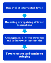 Figure 1: Flowchart of power restoration by conventional method
The Indian Power Grid has developed more complex after the resolution of “One Nation One Grid” by the Central Government. The T&D industries are enduring with R&D challenges like – reliability maintenance, useful life expansion, enhancement of transmission capacity by upgrading/uprating and public & employee safety [2-4]. The overhead transmission lines are covering miles of distance thus; it is exposed to several weather related calamities (e.g., speedy wind, heavy rain, cyclone etc) throughout the wide area [5-7]. Unavailability of electricity due to any of these reasons or may be due to regular maintenance purpose may cause inconvenience to the consumers’ along with financial loss to the service provider [8-16]. These issues could be resolved by improving grid resiliency using ERS bypass arrangement. The proposed ERS usage less time and RoW in compare conventional method of restoration considering following steps (as presented in Figure 1).
Now-a-days, most of the transmission lines are functioning inefficiently due to decay in the transmitting property. Rejuvenation of aging transmission infrastructure is required to boost its efficiency. The key challenges faced by any power transmission system are as below:
· Transmission line congestion
· Fewer private players
· Lack in investments
· Strategic planning unavailability
Transmission line utilities are always trying to reduce customer minutes lost and to avoid any concurrent financial losses [17]. They are always investing in quick restoration technology; even they are getting their manpower trained to counter devastation on emergency basis caused by natural disasters. Previously, such investment was required on a case specific critical components inventory. This led to a major chunk of financial reserves availability to handle such situations [18, 19]. The interchangeable modular ERS structure could be easily transported to even difficult locations and can be reused in future exigencies. The ERS could reduce the inventory of spare towers substantially by using it as temporary service. The installation of ERS was being optimized to overcome site challenges and reduce labour effort with rigorous installation and minutely observing the safety parameter as well enhancing the speed of the process. In this paper, a case study of 400 kV transmission line between Atur and Indira Puram, abandoned since March 2017 and was likely to remain idle due to a 132 kV Single Circuit Transmission line crossing its route.
1.2. Motivation behind the Present Study
Pressure on the existing network to transfer more power has led to transmission line congestion. These issues could be addressed by uprating as it allows considerable increase in power transfer capability within the existing infrastructure. It’s troublesome as shut down is required for reconductoring as these lines are invariably over loaded. The primary concern in emergency restoration is to revive the transmission network and get the line charged and back into operation within the stipulated time frame. These are the key objectives that compelled the development of an ERS tower [20-22].
1.3. Paper Layout
In continuation of aforementioned discussions, remaining study has been presented in succeeding sections. Section 2 presents development of modular ERS structure; while Section 3 deals with reconductoring using ERS, Section 4 focused on overhead transmission line restoration; Section 5 presents observation of the Case Study and finally, the paper has been concluded in Section 6.
2. Development of ERS Module
A quick restoration of power using ERS tower could be made based on certain aspects [23-24], which are as under:
2.1. ERS Design Considerations
A case study has been done on an executed project for UPPTCL. In this paper, the guyed ERS towers were deployed for reconductoring purpose under influence of varying wind speed in between the wind zone 30-55 m/s up to30 m height of tower as per IS:875-1987(Part III).The proposed structure sustained a major bending moment of lateral forces under influence of both tensile and compressive forces. There is optimal allocation of guy wires are required to gain stable workability of the structure. The project was successfully delivered on 5th June, 2017. The whole study could be co-related with following formulations:
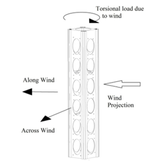 Figure 2: ERS structures’ isometric view
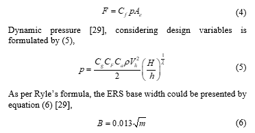
According to metrological requirements of the site, the referred wind speed [25-28] could be given by (1),
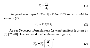 The sectional view shows the side view of the single plane which has oval hollow section to optimize the weight and reduce effective wind pressure on the section. In order to prevent deformation of the structure several construction optimization was done. Significant features of ERS have been briefed as below:
- Erection is very quick due to modular and interchangeable section.
- Minimum numbers of component and identical fittings to reduce identification and segregation process.
- Quick installation with minimum power interruption and cost effective.
- No need of special foundation or tools.
- Erection is possible in any kind of soil and terrain.
- Compatible with 66 kV-765 kV stringing.
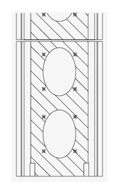 Figure 3: Sectional front view of the ERS module
Wind force [29] imposing on ERS module is given by (4),
 2.2. ERS towers’ Hardware Integration
The ERS tower comprises of multiple components, each of these (as portrayed in Figure 4) are equally important and designed for meeting emergency requirements of the overhead line. Each modular columns (height: 3 m) are identical and fabricated of high strength steel, so they can be easily mounted without following any particular sequence of the complete tower. Foundation plates are designed such it can allow distribution of weight to the ground with minimum load bearing capacity. There was one articulated gimbals joint, which allow linking between foundation plate and sections. The composite insulators were used to reduce RoW issues although at higher voltage levels.
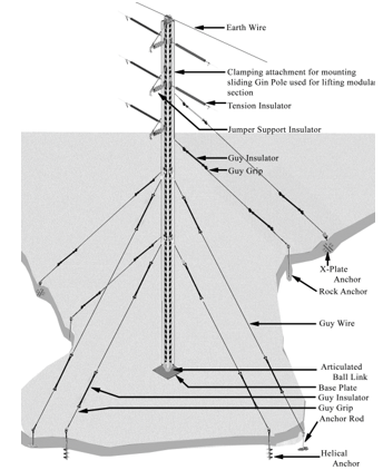 Figure 4: Generalized ERS Set Up.
3. Overhead Transmission Line Restoration
This paper briefly presents a case of electricity transmission from Loni to Mohan Nagar division (UP, India) under following subsections:
3.1. GIS Mapping of the Site
The ERS tower has been utilized at UPPTCL site to re-build 132 kV lines confronting flyover, water passage and street intersections, separately (depicted in Figure 5). However, 132 kV overhead lines was thwarting hanging of 400 kV transmission lines, as height of that line was 51 m from the top most earth wire.
Consequently, a restructuring was made to curtail height of 132 kV by de-amassing second tower (ref to Figure 5) such that, the 400 kV line can be set back on it. Total three ERS towers have been utilized to bypass. Usually, three weeks supply interruption could have been there with conventional method for restoration but application of ERS has delivered this project by 5 hours only. Before initiating execution work of this project, a extensive site survey and planning was done to accomplish this project.
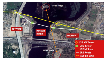 Figure 5: Ghaziabad site restoration layout
3.2. Deployment of Restoration Works
In the current work, three ERSs (height: 30m) were deployed based on the requirements of the specific site UP state, in order to meet resilience and sustainability of bypass arrangement [28]. The analysis of stringing arrangement was performed using PLS CADD software tools. The complete solutions for line restoration or construction of any kind of bypass line by using ERS tower on rental or end to end services basis is being provided, as we have a dedicated team of execute the work. It involves several steps for the enactment of the ERS installation:
Step-1: The initial step involves site survey of the installation site. There are various factors that are taken into account before the installation. A dedicated team is at the first analyses and collects information regarding site. It includes the information such as accessibility to the site, existing tower to ERS tower clearance, RoW clearance, layout of the site, span length etc. Site accessibility also helps to pre-determine the anchor to be used for the type of soil as well kind of tools. After the examination process and collection of all the details, the project engineers proceed towards the next step. The load assessment is done by the design team as per the side condition and feasibility.
Step-2: The second step involves material transportation such as the modular sections and all the equipment that are required for the proper guying and installation of the tower.
Step-3: The third step includes the installation part. Most importantly the major advantage of our ERS towers is that civil foundation is not required. The tower is entirely supported using guy wires. Hence, it is essential that all the guy wires are properly anchored to the soil. Our team took this as a challenge and developed different kind of anchors that would support the structure for different soil conditions.
Step-4: After the installation of ERS base the gimbals joint is then attached to it and with the help of it modular section is installed. Gin poles are used for lifting the next modular sections one by one.
Step-5: For stabilizing the tower guy arrangement has been used. After that all the hardware are installed and conductor stringing is done. Some extra wires are removed to ease the congestion along the axis of the conductor since the tensioned conductor support the tower followed by inspection and joint commissioning to charge the line.
The overhead transmission line has been circumventing from tower-1 to that of -2 by a new root as mapped in Figure 6(a) and erected line was shown in Figure 6(b).
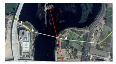 Figure 6(a): Bypass arrangement routing layout
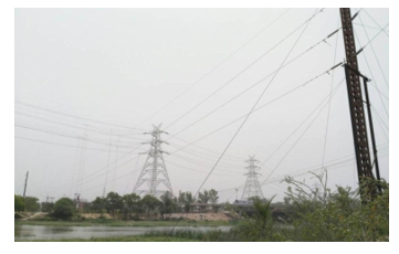 Figure 6(b): Flyover and river crossing
The range existences between re-steered lines are customary cross section tower-1 to ERS-1: 111 m, ERS-1 to -2: 93 m, ERS-2 to -3: 229 m lastly ERS-3 to regular lattice tower-3: 250 m. In continuation with site overview, skilled team with their tools deployed to pursue the project.
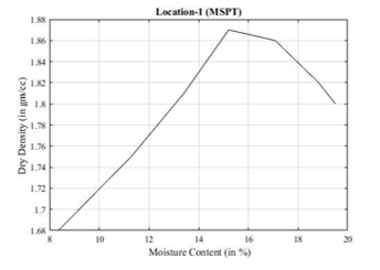 Figure 7: Characteristics of MSPT test for soil sample-1.
4. Observations from Case Study
The heavy compaction test has been tested for soil samples taken from location-1 and -2 while; light compaction test is found to be appropriate for location-3. These types of test were carried out to check MDD and OMC of soil as per IS: 2720 (Part VIII) 1983. The field dry density core cutter testing method complying IS:2720 (Part VII & XXIX) has been performed across the field at each location as shown in Table 1.
Table 1: Field test findings from core cutter method.
| Parameters | Sample- 1 | Sample- 2 | Sample-3 |
| Field BD (gm/cc) | 1.93 | 1.91 | 1.92 |
| Field MC (%) | 4.79 | 6.16 | 4.82 |
| Field DD (gm/cc) | 1.84 | 1.80 | 1.83 |
| DD ( % of MDD) | 98.39% | 96.25% | 97.86% |
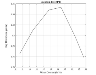 Figure 7: MSPT test characteristics of soil sample-2.
The recorded test findings of moisture content and dry density are provided in Table 2 and their graphs are plotted in Figure 7-9. The interesting outcomes (OMC & MDD) are highlighted by boldfaced in the subsequent column of Table 1. The compaction test observations exceeding 95% of the MDD; thus, the site was viable to erect the ERS tower.
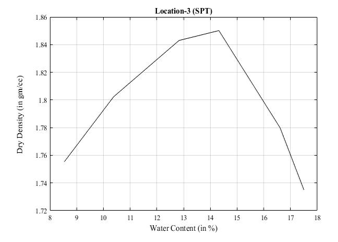 Figure 8: SPT test characteristics of soil sample-3
Table 2: Results obtained after compaction test
| Locations | Testing methods | Parameters | |
| Content of moisture (%) | Dry density (gm/cc) | ||
| 1 | MSPT | 8.360 | 1.68 |
| 11.29 | 1.75 | ||
| 13.41 | 1.81 | ||
| 15.21 | 1.87 | ||
| 17.08 | 1.86 | ||
| 18.83 | 1.82 | ||
| 19.50 | 1.80 | ||
| 2 | MSPT | 8.600 | 1.766 |
| 10.44 | 1.809 | ||
| 12.74 | 1.848 | ||
| 14.45 | 1.853 | ||
| 16.51 | 1.796 | ||
| 17.68 | 1.758 | ||
| 3 | SPT | 8.540 | 1.76 |
| 10.38 | 1.80 | ||
| 12.83 | 1.84 | ||
| 14.32 | 1.85 | ||
| 16.61 | 1.78 | ||
| 17.50 | 1.73 | ||
Table 3: Site specific benefit comparison
| S. No. | Particulars | Restoration using ERS | Conventional restoration |
| 1 | Structural footprint | <1 m2 | 36-64 m2 |
| 2 | Foundations of structure | Not required. | Depth: 2-4 m |
| 3 | Angle of protection | ||
| 4 | Down time of supply | 5 Hours | 20 Days |
| 5 | Average value of power flow | 5 MW | 5 MW |
| 6 | Generation loss/day | 120000 Units | 120000 Units |
| 7 | Unit price | INR 2.5 | INR 2.5 |
After execution of this project, a cost-benefit analysis was made (given in Table 3) to ascertain future scope of ERS in service customers.
5. Conclusion
Indeed, even in open vitality markets, electricity transmissions are normally considered as a usual monopoly and sometimes bring contests among investors. This starts leapfrogging of new ideas so as to get by in the aggressive power industry. Thusly, development of ERS gives an elective potential answer for detour the customary transmission tower for rebuilding just as line reconductoring. Line uprating proves to be a smart solution to cater the increased loads on existing transmission lines. However, this exercise is problematic as the shutdown required for reconductoring cannot be provided as those lines are already critical. This exercise helped in completing a project which would evacuate 580 MW lines where substantial investment was already made on 98% stretch of the line and associated substation would have remained idle for indefinite period. Project milestones and achievements are concluded as below:
- Line Crossing: Stringing was challenging as the line had a flyover, a river and a highway crossing
- Delay in Shutdown: Even after installing the ERS, re-tapping was frenetic due to shutdown required for 2 hours from UPPTCL was difficult.
- No Heavy Machinery: No heavy machinery or earth movers were introduced for execution of above, other than for transportation, which depicts the agility of the system.
- Challenging Feat: The bypass line across the highway was done without any disruption of highway traffic even for a minute.
- Rough Weather: There was stormy wind after erection but no damage was made to the ERS.
Conflict of Interest
Authors are declaring that there is no conflict of interest with any other individual or organization.
Acknowledgement
The project shown as a case study was done for UPPTCL, India. Authors are thankful to Mr. Arup Das (SCPL) and Mr. Prakash Reddy (SCPL) for their active co-operation.
- “World Energy Outlook Special Report : India Energy Outlook” International Energy Agency, 2015.
- O. H. Abdalla, T. M. Alkhusaibi, M.A. Thani, M. N. Alkhusaibi, “Restoration of a 132 kV Over Head Transmisssion Line affected by Tropical Cyclone Gonu in Oman” in IEEE Proc. Transm. Distrib. Conf. and Expo., 1-5, 2008. DOI: 10.1109/TDC.2008.4517063
- L. N. Agrawal, P. E. Erickson, “Planning and Training reduce Restoration time for damaged transmission lines in Inida” in Int. Proc. on Transm. and Distrib. Constr., Oper.and Live-Line Maint., 101-108, 2000. DOI: 10.1109/TDCLLM.2000.882807
- M.I. Khan, D. Prasad, K. Sarkar, S. Mukherjee, P. Barua, H. Agarwal, 2019, March. Finite Element Modeling of 400 kV ERS Bypass Transmission Line Quantifying Installation Difficulty. In 2019 IEEE PES GTD Grand International Conference and Exposition Asia (GTD Asia) (pp. 526-531). IEEE. 10.1109/GTDAsia.2019.8715871
- D. Prasad, R. Kumaran, G. Agarwal, P.K. Reddy, Md. I. Khan, 2016. Emerging Solutions for Line Compaction. CIGRE India Journal, 5(2), pp. 21-26.
- S. Mukherjee, D. Prasad, Md. I. Khan, P. Barua, H. Agarwal, 2019. Hexa Spacer Damper for Vibration Energy Decaying of 765 kV Transmission Line. 2nd International Conference on Innovations in Power and Advanced Computing Technologies, i-PACT-2019, on 22nd – 23rd March, 2019 at Vellore Institute of Technology, Vellore, India.
- D. Prasad, V. Mukherjee, 2016. A novel symbiotic organisms search algorithm for optimal power flow of power system with FACTS devices. Engineering Science and Technology, an International Journal, 19(1), pp.79-89. 10.1016/j.jestch.2015.06.005
- D. Prasad, A. Mukherjee, V. Mukherjee, 2017. Application of chaotic krill herd algorithm for optimal power flow with direct current link placement problem. Chaos, Solitons & Fractals, 103, pp. 90-100. 10.1016/j.chaos.2017.05.037
- D. Prasad, A. Mukherjee, G. Shankar, V. Mukherjee, 2017. Application of chaotic whale optimisation algorithm for transient stability constrained optimal power flow. IET Science, Measurement & Technology, 11(8), pp.1002-1013. 10.1049/iet-smt.2017.0015 10.1049/iet-smt.2017.0015
- D. Prasad, A. Mukherjee, V. Mukherjee, 2017. Transient stability constrained optimal power flow using chaotic whale optimization algorithm. In Handbook of neural computation (pp. 311-332). Academic Press. 10.1016/B978-0-12-811318-9.00017-X
- D. Prasad, V. Mukherjee, 2018. Solution of optimal reactive power dispatch by symbiotic organism search algorithm incorporating FACTS devices. IETE Journal of Research, 64(1), pp.149-160. 10.1080/03772063.2017.1334600
- V. Mukherjee, A. Mukherjee and D. Prasad, 2018. Whale Optimization Algorithm with Wavelet Mutation for the Solution of Optimal Power Flow Problem. In Handbook of Research on Predictive Modeling and Optimization Methods in Science and Engineering (pp. 500-553). IGI Global. 10.4018/978-1-5225-4766-2.ch023
- D. Prasad, A. Banerjee, R.P. Singh, 2019. Optimal Reactive Power Dispatch Using Modified Differential Evolution Algorithm. In Advances in Computer, Communication and Control (pp. 275-283). Springer, Singapore. 10.1007/978-981-13-3122-0_26
- A. Banerjee, D. Prasad, R.P. Singh, 2015. Smart reactive power control of hybrid power system model by Seeker Optimized Algorithm. In ETES-2015 conference organized by IET on 16-17th July, 2015 at Asansol, West Bengal, India.
- R.P. Singh, A. Banerjee, D. Prasad, 2014. Solution of optimal power flow problem using modified differential evolution algorithm. In ETES-2014 conference organized by IET at Asansol, West Bengal, India.
- R.P. Singh, D. Prasad, P. Kumar, and M.I. Khan, 2017, August. Modified differential evolution algorithm for optimal power flow with FACTS devices. In 2017 International Conference on Smart grids, Power and Advanced Control Engineering (ICSPACE) (pp. 48-52). IEEE. 10.1109/ICSPACE.2017.8343404
- N. Ozog, E. Desjardins, J. Jatskevich, “Bulk power system restoration interdependency risk modelling” in IEEE Proc. Elect. Power Energy Conf., 1-7, 2008. DOI: 10.1109/EPC.2008.4763347
- R. J. Schweiner, K. E. Twomey, K. E. Lindsey, “Transmission Line Emergency Restoration Philosophy at Los Angeles Department of Water and Power,” in IEEE Proc. Transm. and Distrib. Constr., Oper. Live-Line Maint., 11-17, 2003. DOI: 10.1109/TDCLLM.2003.1196462
- J. C. Pohlman, “The case for Universal Standards to cover the structural components and practices used in Emergency Restoration Systems” in Int. Proc. on Transm. and Distrib. Constr., Oper.and Live-Line Maint., 109-115, 2000. DOI: 10.1109/TDCLLM.2000.882808
- J. F. Nolasco, P. Nefzger, U. Kaintzyk, Overhead power lines: Planning, Design, Construction, Springer, 2003.
- T. S. Kishore, S. K. Singal, “Optimal economic planning of power transmission lines: A review” Ren. and Sust. Energy Rev., 39(5), 949-974, 2014.https://doi.org/10.1016/j.rser.2014.07.125
- L. Bauer, P. Ulardic, J. Muller, “Reinforcement Strategies for Extending the Service Life of 110 kV Overhead Transmission Lines” in Int. Conf.and Exhibition on Electr. Distr., 1997. DOI: 10.1049/cp:19970547
- S. G. Krishnasamy, G. L. Ford, C. I. Orde, “Predicting the structural performance of transmission lines uprated by reconductoring” IEEE Trans. Power Appar. Syst., 100(5), 2271-2277, 1981. DOI: 10.1109/TPAS.1981.316740
- “Conductors for the Uprating of Existing Overhead Lines,”CIGRÉ WG B2.55 Brochure (Ref. No. TB 244), 2003.
- A. Marin, J. Salmeron, “Electric capacity expansion under uncertain demand:decomposition approaches” IEEE Trans. Power Syst., 13(2), 333-339, 1998. DOI: 10.1109/59.667347
- I. Albizu, A. J. Mazón, I. Zamora, “Methods for Increasing the Rating of Overhead Lines” in Power Tech IEEE Proc., Russia, 1-6, 2005. DOI: 10.1109/PTC.2005.4524481
- M. T. Chay, F. Albermani and H. Hawes, “Wind loads on transmission line structures in simulated downbursts,” in First World Congress on Asset Management, Gold Coast, Australia, 2006.
- S. S. Murthy, A. R. Santhakumar “Transmission line structures,” McGRAW-HILL Book Co., 1990.
- P. J. Ryle, “Steel tower economics” J. Inst. Electr. Eng. – Part II: Power Eng., 93(33), 263-274, 1946. DOI: 10.1049/ji-2.1946.0063
- H. Niroumand, Soil reinforecement for anchor plates and uplift response, Butterworth-Heinemann, 2017.
- J. C. Kaltenbach, J. Peschon, E. H. Gehrig “A mathematical optimization technique for the expansion of electric power transmission systems” IEEE Trans. Power Appar. Syst., 89(1), 113-119, 1970. DOI: 10.1109/TPAS.1970.292677