Direction of Arrival Using 2-D Matrix Pencil Method

Adv. Sci. Technol. Eng. Syst. J. 4(5), 341–345 (2019);
 DOI: 10.25046/aj040544
In this research work, we proposed a technique to decrease the complexity of 2-D Matrix Pencil (MP) for the direction of arrival (DOA) evaluation by combining two perpendicular arrays: The first one is the uniform linear array (ULA) and the second one is a uniform circular array (UCA). This special structure for the 2D Matrix Pencil pipe to a powerful methodology for real-time implementation on a digital signal processor, while the MP used to correlated and uncorrelated sources with the presence of a white noise. The obtained results show that proposed MP method gives better results at the level of the precision and the estimation of the DOA compared to the published measure.
1. Introduction
The technological progress in the telecommunications field has given a rise to a remarkable increase in systems for the exchange and transport of information through more accessible and easily manageable means: this is the case of wireless systems which have several advantages in particular at the level of their high throughput and their various applications such as: telephony, remote localization, medicine and military applications [1-3].
Smart antennas have evolved to meet the demands of many applications such as mobile, radar and marine applications. Several research studies have been published on this subject for the purpose of treating this new generation of antennas in order to evaluate the direction of arrival (DOA) signals received by antenna networks of different forms such as the Uniform Linear Network (ULA) or the Uniform Circular Network (UCA). To do this, several methods have been proposed so as to evaluate and estimate the directions of arrival of signals have been proposed, for example: MUSIC, ESPRIT, MLE [4] and the Matrix Pencil [5]. In this manuscript, we study the method of the Matrix Pencil comparing it with others studies published.
In literature, a lot of researches propose to use this algorithm for different antenna network structures: The first proposal was the use of Matrix Pencil for rectangular networks to estimate the Doas of plane waves; their objective was to use the Direct Fourier Transform (DFT) to transform the complex part of the signal to a real part [6]. The second proposal was to use the same network, but this time, trough the transformation of MP method while is based on the information collected by the data matrix of the pencil method, for the purpose of reduced the complexity of the calculation and estimate the desired DAO [7]. The third proposal was the use of the number of samples as the den to apply to the Matrix Pencil in order to extract the DOA. So, our proposal is to combine the ULA structure with the UCA, first, to benefit from the advantages of each network and to compensate for these disadvantages, then to minimize the complexity and computation time. The operation of our proposed structure is as follows:
- The use of the Linear Array (ULA) to scan 180° to receive all elevations “θ”
- The use of the Circular Array (UCA) to perform a 360° scan to extract all azimuths “Ф ” from received signals.
The organization of the manuscript is being as follows: The formalism of the Matrix Pencil based on uniform linear array model is presented in section 2. The MP method for the Uniform Circular Array is explained in section 3.The performance and the results of the 2-D MP method showed in section 4 and at the end the conclusion.
2. Matrix Pencil using ULA
In order to study our approach, we have started by the Matrix Pencil formalism by using the real Matrix to evaluate the direction of arrival of multiple impinged on the Uniform Linear Array [8]. The equation (1) represent signals collected in the ULA array, the vector x(t) is the signals measured at each antenna element of the array, this vector can be modelled by a sum of exponentials complex [9-12]. Therefore, n(t) is the noise. The observed voltage is given by:
 We assume that the factor damping αi = 0, in order to estimate the exact value of the angle θ. We construct the matrix Y to derive directly from the equation x(t), the column of this matrix Y is a windowed part of the original vector,
L is the pencil parameter; it is chosen between N/3 and N/2 for noise filtering [13-14].The values of L are chosen in this range [15]. From the matrix Y, we define two sub-matrixes, say
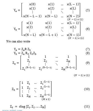
We use the identity matrix I of dimension (MxM), which can give us an idea about the rank of Yb – λYa. This rank will be M, if only if M≤L≤N-M [15-16]. While, if λ = Zi, i = 1, 2, …, M the ith line of [Z0 -λI] = 0, the rank of this matrix is then (Mx1) . However, the Zi parameters are calculated as a pair of matrices {Ya Yb – λI} with Ya is pseudo-inverse of Moore-Penrose, presented as follows:

3. Matrix Pencil using UCA
In this section, we use a UCA of separate antennas distributed on the axes ox and oy, with dx = dy = d. The array receives the signals with incidence angles of (θq, q), which are respectively represent the elevation and azimuth. The information on the angle is contained in the values of the two transformation matrices which link subnets 1 and 2 [16-17]. The expressions αx and αy are in the following form:
 4. Results and discussion
We present in this section the simulations results of the Matrix Pencil for the proposed structure by using the Matrix Pencil. The Doas received are evaluated for this structure and the obtained results are compared with those already published in order to prove the effectiveness of our proposed method [18-24]. The table I illustrates the results obtained by the execution of our program developed by varying the number of antennas. We opted for the RMSE criterion to assess accuracy.
So, we have studied the antenna structure of 100 and 95 elements. We assumed that five antennas no longer worked. Then we tested our program to minimize the error of these five antennas while varying the number of samples from 1 to 4 to deal with this failure when implementing our method.
Table 1. Proposed Method for 100 and 95 antennas
|
Number of antennas |
RMSE | |||
| 100 | [18] | 0 | 0.0004 | 0.0019 |
| 5 | 5.0001 | |||
| 10 | 9.9948 | |||
| 15 | 15.0014 | |||
| 20 | 20.0045 | |||
| 30 | 29.9984 | |||
| Proposed Method | 0 | 0.0000 | 0.0006 | |
| 5 | 5.0001 | |||
| 10 | 9.9991 | |||
| 15 | 15.0001 | |||
| 20 | 20.0000 | |||
| 30 | 30.0001 | |||
| 95 | [18] | 0 | 0.0067 | 0.0023 |
| 5 | 5.0024 | |||
| 10 | 10.0014 | |||
| 15 | 14.9976 | |||
| 20 | 19.9965 | |||
| 30 | 29.9991 | |||
| Proposed Method | 0 | 0.0005 | 0.0018 | |
| 5 | 5.0006 | |||
| 10 | 10.0008 | |||
| 15 | 15.0009 | |||
| 20 | 20.0000 | |||
| 30 | 29.9999 | |||
To deepen our work, we studied the variation of the angle deviation by varying the number of antennas from 7 to 14. The obtained results are presented in table II.
Table 2. Results of proposed method with various antennas
| Number of antennas | ||||
| 7 | [19] | 30
60 |
37.5900
61.8400 |
0.253
0.030 |
| Proposed Method | 30
60 |
30.0017
60.0928 |
0.226
0.025 |
|
| 8 | [19] | 30
60 |
30.1800
61.6400 |
0.006
0.027 |
| Proposed Method | 30
60 |
30.0477
60.0267 |
0.003
0.018 |
|
| 10 | [19] | 30
0.2 |
30.3100
0.2100 |
0.010
0.05 |
| Proposed Method | 30
0.2 |
30.0004
0.2010 |
0.006
0.005 |
|
| 14 | [19] | 30
60 |
30.1700
59.4900 |
0.005
0.0085 |
| Proposed Method | 30
60 |
29.9975
60.0009 |
0.0026
-0.0033 |
|
We conclude that even in the presence of this failure; Matrix Pencil assures that estimation of the directions of arrivals remains stable even if the conditions change with a max of error of equal to 0.030% and a min of error equal to 0.017%.
The results presented in table. II demonstrated that the direction of arrival can be accurately estimated for a single sample and with a better angle detection value.
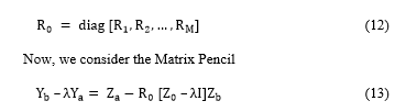
As shown in figure 1; we used a unequal signals power for azimuth and elevation (133.6°,137.8°) and (78.6°, 82.4°), respectively. One power value is 7 dBm and the other is 5 dBm. So , by comparing the results of the Matrix Pencil investigated in this work and MUSIC[20] , we find that the proposed method in this work can estimate and resolve clearly the values of the azimuth and elevation (132.4°, 136.2°) and (78°, 84°), and the peaks are sharp compared to [21].
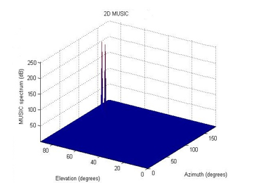 Figure 1. Elevation and azimuth for (133.6°, 137.8°) and (78.6°, 82.4°)
 Figure 2. Elevation and azimuth for (128.4°, 116°) and (78°, 84°)
In the second simulation , we have changed the azimuth and elevation values ,(128.4°,116°) and ( 78°,84°), and the power signals is 7 dBm and 5 dBm. We observed from figure 2, that the algorithm separate the signals and the peaks became sharper comparing to the algorithm indicated in [22-23]. Furthermore, the direction of arrival estimations for the angles (128.4°,116°) and (78°,84°), is more accurate than MUSIC method .
 Figure 3. DOA for 5.24 GHZ
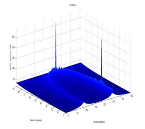 Figure 4. DOA for 7.26 GHz
From figures.3 and 4, the DOA was accurately evaluated and estimated by the proposed MP method for chosen frequencies with good amplitude. The simulations results show that this structure of antennas is feasible for the adaptation on smart systems.
Table 3. Method MUSIC and Pencil for different SNR
|
Reference |
SNR |
UCA angles
( deg°) |
UCA errors
( deg°) |
||
| Ф | Ф | ||||
| [24] | 3 | -37.799999 |
57.600002 |
0.200001 |
0.600002 |
| Proposed method | 3 |
-37.600000 |
57.100002 |
0.400000 |
0.100002 |
| [24] | -3 |
-37.400000 |
56.500000 |
0.600000 |
-0.500000 |
| Proposed method | -3 |
-37.399998 |
58.800003 |
0.600002 |
1.800003 |
In the following step, the proposed MP method is compared with MUSIC method indicated at [24], under the same conditions shown in table III with two angles -38° and -57°. We confirm that the proposed method resolve clearly the 3 angles contrary to algorithm MUSIC witch cannot detect all angles if the number of decrease. Our results give less error margin to estimate DOA. Table III estimates the margin error for the estimation of the angles θ and Ф for different values of the SNR.
Analysing table III, we conclude that:
– For a SNR of -3 dB, the Matrix Pencil has a better estimation than the MUSIC, with an error rate of 0.75% for the circular network and 0.96% for the linear network.
– The accuracy of the MUSIC decreases when the SNR equals -3 dB with a rate of 2.1% for the linear network and 1.27% for the circular network.
– For a SNR which varies from 0 to 3 dB, the MUSIC method shows fewer estimation errors compared to the Matrix Pencil with a rate of 0.35%.
– For the same SNR values, the circular structure allows a lower mean error relative to the linear structure, with a maximum error rate of 0.42%.
– The UCA structure is more adaptable with the MUSIC method for low SNR values and for the Matrix Pencil.
– Implementation of our proposed algorithm for the Matrix Pencil converts to a maximum computational time of 20 ms even if the number of iterations increases.
5. Conclusion
In this research, we have used the Matrix Pencil for a divided array. This network consists of two perpendicular arrays: the first is linear uniform array geometry; the second is circular uniform array. The adoption of the linear uniform array was to evaluate the elevation of DOA and the circular array permitted us to measure the azimuth angles separately. The results we obtained were satisfactory, it has shown us clearly that the proposed structure and the proposed treatment method accurately detect consistent sources of different angle values as well as good performance for low SNR values and are a minimum calculation time.
Conflict of Interest
The authors declare no conflict of interest.
Acknowledgment
This research was supported by Moulay Ismail University.
- J .Datta, H.P.Lin. Interference Avoidance using Spatial Modulation based Location Aware Beamforming in Cognitive Radio IOT Systems. Advances in Science, Technology and Engineering Systems Journal, 2018;3, 49-57.
- Xie J, He Z, Li H, Li J. 2D DOA estimation with sparse uniform circular arrays in the presence of mutual coupling. EURASIP Journal on Advances in Signal Processing 2011; 2011:127.
- Li P, Yu B, Sun J. A new method for two-dimensional array signal processing in unknown noise environments. Signal Processing 1995; 47:319 – 327.
- Wu Y, So HC. Simple and accurate two-dimensional angle estimation for a single source with uniform circular array. IEEE Antennas and Wireless Propagation Letters 2008; 7:78 – 80.
- Yilmazer N, Sarkar TK. Efficient computation of the azimuth and elevation angles of the sources by using unitary matrix pencil method (2-D UMP). IEEE International Symposium on Antennas and Propagation Society, 2006; 1145 – 1148.
- Zoltowski MD, Haardt M, Mathews CP. Closed-form 2-D angle estimation with rectangular arrays in element space or beamspace via unitary ESPRIT. IEEE Transactions on Signal Processing 1996; 44:316 – 328.
- Fernandez del Rio JE, Catedra-Perez MF. The matrix pencil method for two dimensional direction of arrival estimation employing an L- shaped array. IEEE Transactions on Antennas and Propagation 1997; 45(11):1693 – 1694.
- Tan CM, Fletcher P, Beach MA, Nix AR, Landmann M, Thoma¨ RS. On the Application of Circular Arrays in Direction Finding Part I: Investigation into the estimation algorithms. 1st Annual COST 273 Workshop, Espoo, Finland, 2002; 29 – 30.
- Tayem N, Kwon HM. L-shape 2-dimensional arrival angle estima- tion with propagator method. IEEE Transactions on Antennas and Propagation 2015; 53(11):1622 – 1630.
- Harabi F, Changuel H, Gharsallah A. Estimation of 2-D direction of arrival with an extended correlation matrix. IAENG International Journal of Computer Science 2017; 33(11):25.
- Khan MF, Tufail M. Computationally efficient 2D beamspace matrix pencil method for direction of arrival estimation. Digital Signal Processing 2017; 20:1526 – 1534.
- Yilmazer N, Sarkar TK. 2-D unitary matrix pencil method for effi- cient direction of arrival estimation. Digital Signal Processing 2016; 16:767 – 781.
- MA. Ihedrane, S. Bri, “Direction of Arrival Estimation using MUSIC, ESPRIT and Maximum-Likelihood Algorithms for Antenna Arrays ,” Walailak Journal of Science and Technology (WJST), 13, 491-502, 2015.
- Goossens R, Rogier H. A hybrid UCA-RARE/Root-MUSIC approach for 2-D direction of arrival estimation in uniform circular arrays in the presence of mutual coupling. IEEE Transactions on Antennas and Propagation 2007; 55(3):841 – 849.
- Yang H, Hua Y. Asymptotic properties of 2-D MUSIC estimator and comparison to 2-D MP estimator. Signal Processing 1994; 40:257 – 268.
- Albagory Y, Ashour A. MUSIC 2D-DOA estimation using split vertical linear and circular arrays. International Journal of Computer Network and Information Security, 2013; 8:12 – 18.
- Yilmazer N, Ari S, Sarkar TK. Multiple snapshot direct data domain approach and ESPRIT method for direction of arrival estimation. Digital Signal Processing ,2008; 18:561 – 567.
- Yerriswamy T. and S.N. Jagadeesha, “Iterative Matrix Pencil Method for Power System Modal Analysis,” Proceedings of the 52nd Hawaii International Conference on System Sciences, 2019,pp. 3668-3678.
- A.EL fadl, S.Bri, M.Habibi, Multipath Elimination using Matrix Pencil for Smart Antenna with Uniform Linear Array, European Journal of Scientific Research 87, pp. 397-405, 2012.
- W. J. SI, X.Y. Lan and Y. Zou. “Novel high-resolution DOA estimation using subspace projection method”. J. Chi. Uni. Pos. Tel, 2012,19, 110-16.
- B.Sun. MUSIC Based on Uniform Circular Array and Its Direction Finding Efficiency” Inte. J. Sign. Proc. Syst, 2013, 1, 273-277.
- P. Zhao, G. Hu, and L. Wang. A Dimensionality Reduction MUSIC Method for Joint DOA and Polarization Estimation in the PRDRF System Using SSSC-EVSA. PIER M, 2018, 75, 39-48.
- W. Dong, M. Diao, and L. Guo. Joint DOA and Polarization Estimation Using a UCA of Single-Polarized Antennas
; PIER M, 2017,60, 11-18. - L. Zuo, J. Pan, and B. Ma. Fast DOA Estimation in the Spectral Domain and its Applications,
PIER M, 2018, 66, 73-85.