
Resonator Influence Simulation of Designed Close-Open Standing Wave Thermoacoustic Engine
Volume 4, Issue 5, Page No 300-305, 2019
Author’s Name: Sugiyanto1,2,a), Samsul Kamal1, Joko Waluyo1, Adhika Widyaparaga1
View Affiliations
1Department of Mechanical and Industrial Engineering, Faculty of Engineering, Gadjah Mada University, 55281, Indonesia
2Department of Mechanical Engineering, Vocational School, Gadjah Mada University, 55281, Indonesia
a)Author to whom correspondence should be addressed. E-mail: sugiyanto_t@ugm.ac.id
Adv. Sci. Technol. Eng. Syst. J. 4(5), 300-305 (2019); ![]() DOI: 10.25046/aj040538
DOI: 10.25046/aj040538
Keywords: SWTE, Length of Resonator Tube, Acoustic Power

Export Citations
Thermo-acoustic technology is very potential to be applied to convert heat into another energy source. The complete thermoacoustic engine construction requires a resonator connected to a core where there is a heat exchanger. The thermoacoustic core has a function as an acoustic power generator while the resonator functions as a storage of acoustic power which will shift the amplitude or phase of oscillating pressure or volume flow rate. Experimental testing was carried out to obtain the performance of a quarter wave length of standing wave thermoacoustic engine (SWTE). The resonator is made of a 2 inch Sch 40 stainless steel pipe with a length of 390 mm. The results of this experiment showed that the measured pressure amplitude was 4800 kPa with a working frequency of 138 HZ and produced an acoustic power of 22.85 watts. The parameters of this experimental test are used for the simulation program. The acoustic power generated from the simulation is 20.13 watts, 18.67 watts and 17.82 watts respectively for the length of the resonator 390 mm, 780 mm and 1170 mm.
Received: 28 May 2019, Accepted: 15 September 2019, Published Online: 15 October 2019
1. Introduction
Thermoacoustic is a technology related to heat transfer to pressure oscillation, so the use of the term “Thermo” comes from the heat transfer process while “acoustic” comes from pressure oscillating in the working fluid. This term was first introduced by [1] who was credited with laying a theoretical foundation for the field of thermoacoustic research. Thermoacoustic technology is more interesting to develop because of its superiority compared to traditional energy conversion system technologies [2]. The advantage lies in thermoacoustic devices that have immovable components and simple construction (basically pipelines), making such systems very reliable and requires low construction and maintenance costs.
Thermoacoustic devices classified into thermoacoustic engine (TAE) and thermoacoustic refrigerators (TAR) depending on the practical application of the thermoacoustic effects. TAE turns thermal energy into acoustic energy. The thermal energy comes from a significant temperature difference derived from a heat exchanger that applied to two ends of porous material. TAR converts acoustic energy into temperature differences utilizing acoustic waves imposed along with porous material. This process causes temperature differences that occur in the two heat exchangers [3].
The main components of a TAE or TAR are a resonator tube, a porous material (stack) and two heat exchangers. A standing wave type produces a half wavelength or a quarter wavelength which generate in the resonator. The thermoacoustic phenomenon takes place in porous material when the temperature gradient that is worn along the porous material interacts with the oscillation of sound waves. The heat exchanger is responsible for transferring heat in and out of the thermoacoustic device at the desired temperature, thereby maintaining the temperature gradient applied to the porous material [4].
Swift [5] built and tested this SWTE using a 5-inch diameter stainless steel pipe with electric heating. The working fluid used is Helium at an average pressure of 13.8 bar. The result is an acoustic power that can be generated at 630 W with an efficiency of heat conversion to acoustic power of 9% and a Carnot efficiency of 13%. Thermoacoustic prime mover (TAPM) which has a resonator length of 128 cm, uses a stack of stainless-steel mesh numbered 14, two heat exchangers and water at atmospheric pressure as gas acting inside the resonator. Successfully designed, built, and evaluated by [6].
There are two types of acoustic waves generated by the thermoacoustic engine, standing waves, and traveling waves. Both of these wave types depend on the type of resonator used. Thermoacoustic engines require high-temperature gradients to produce sound. The temperature gradient itself occurs in part often called the stack (for a traveling wave thermoacoustic engine called a regenerator), placed between the hot and cold sides of the thermoacoustic engine. Thermoacoustic engine research mostly is done on the standing wave type due to its ease of configuration, which only consists of a resonator pipe and the thermoacoustic core which is directly connected to the resonator and placed near the other end. This thermoacoustic core is a heat exchanger (HHX), stack, and cold heat exchanger (CHX).
The influence of the length of the resonator pipe on frequency is carried out by [7] who investigate the performance of prime mover thermoacoustic traveling waves at a small onset temperature difference, which is obtained by mounting the stack in the right position on the horizontal resonator pipe.
The resonator tube is one of the critical components of a thermoacoustic engine. Many studies have been conducted on the effect of resonance tube on thermoacoustic performance, most of them focused their research on resonance tube length which is considered the dominant factor that determines the frequency of the system
The effect of the resonance tube on a standing wave thermoacoustic engine is researched by simulating a linear thermoacoustic. In this simulation, the SWTE is connected to a pulse tube refrigeration to obtain the temperature gradient on the core side. The results of this simulation calculation show that the prolongation of the resonance tube can cause a decrease in the working frequency [8].
Hariharan et al. [9] conducted a study with variations in stack geometry and resonator length to determine the SWTE performance. In this study, variations in the length of the resonator carried out with lengths of 200, 300, 400, and 500 mm. Variation of the length of the resonator influences the pressure amplitude, wave frequency, and acoustic power so that it will also affect its efficiency.
The TAE model whose resonator length can be regulated was examined by [10] which consisted of 103 mm ceramic honeycomb stack, volume buffers, and shell-tube type heat exchangers. The TAE performance was evaluated using six different types of stack. The length of the resonators used were 50 mm, 100 mm, and 150 mm placed in three different places. The length of the resonator that can be set in this study aims to choose the best working frequency so that the TAE can work optimally and produce the highest acoustic power.
The influences of the tube diameter of traveling wave thermoacoustic are not sensitive; hence, the resonance frequency of the radial dimension is always ignored. Therefore, the way to adjust the working frequency is to vary the length of the resonator tube. However, for a small thermoacoustic system, the influence of the radial dimension cannot be neglected [11].
The resonator is one of the key components of a thermoacoustic engine because it’s save acoustic power. Resonator supply the instances and compliances that the working frequency is related to it. The unwanted eddying or non-linear pressure variations should be avoided by using a straight tubular resonator pipe without step, misalignment, and sudden transition. However, A straight, uniform-diameter resonator is seldom the best design [12].
This paper is an extension of work originally presented in the 2018 4th International Conference on Science and Technology (ICST), by changing some variations but still focusing on simulations as a way to analyze the performance of this SWTE. The author has conducted research on the effects of resonator diameter on SWTE performance by simulations using DeltaEC. The results show that the simulations with resonator diameter variations from the close-open SWTE have no significant effect [13].
Experiment testing was conducted beforehand to get the results of the parameters used. The results of this experiment will be used to validate the results of the simulation. The parameters of the simulation results that have been confirmed with settings in the SWTE experiment are then used as SWTE simulation parameters in variation length of the resonator. Simulation of an SWTE is easy to do using DeltaEC . This program was made by Dr. Bill Ward and Dr. Gregori Swift from Los Alamos National Laboratories (LANL) [14].
2. Theoretical basis
The quarter wave length resonator is a tube closed at one end and open at the other. This resonator can be explained in a lumped element model consisting of compliance in series with inertance [15].The working frequency is related to the inertance (L) and compliance C) of the component in the thermoacoustic engine, and they can be described by the equation [12]:
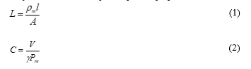 Where A and l are the sectional area and length of the resonator tube, respectively. ?m is average density and Pm is the pressure of the gas. V and γ are the volume compliance and the specific heat, respectively.
The acoustic intensity I for the measured sound wave was calculated using the modified two sensor method [16]:
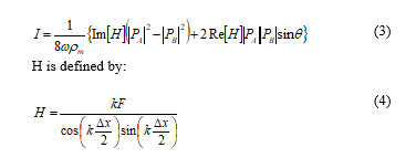 Where Re [ ] is the real component and Im [ ] is the imaginary components. PA and PB are acoustic pressure waves measured by pressure sensors mounted close together along the resonator, and θ = arg [PA/PB] represents phase lead of pressure wave PA relative to PB, k is complex wave number and Δx is the difference in distance between the two pressure sensors.
F is a complex factor calculated by:
![]()
 Where γ and σ is notation of the specific heat ratio and Prandtl number, respectively. Jn represent the nth order complex of Bessel function, k0 is the wave number, and r0 is the radius of duct.
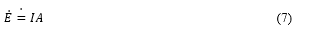
The results of the acoustic intensity calculation (I) are then used to calculate the acoustic power in the following equation:
 3. Methodology
This research uses an SWTE that is open at the end of the resonator but closed at the end adjacent to the thermoacoustic core as seen in Figure 1. Resonators are made of 2-inch Sch. 40 stainless steel pipes with a length of 390 mm. Two heat exchanger devices used are made of copper both for hot heat exchangers (HHX) and cold heat exchangers (CHX). Both of these heat exchangers flank the stack made of stainless-steel wire mesh, with a porosity of 88.26%. The heat source for heating the HHX comes from 6 pcs glow plug from an 11 VDC diesel engine, and CHX is cooled using water.
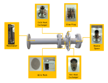 Figure 1: The main components of a close-open thermoacoustic engine
The first step is experimental testing to find out the acoustic intensity of SWTE with a resonator length of 390 mm. In this experimental test, temperatures were measured using two type-K thermocouples placed in HHX (hot side) and CHX (cold side) connect to National Instrument 9234 module. Two M102A05 PCB pressure sensors are mounted on the resonator with a distance between them of 50 mm, used to measure acoustic pressure with readings using the National Instrument module 9234 as well. As a heat source, 6 glow plugs from diesel engines are used which are connected to the transformer battery charger. The set-up of this experimental test is shown in Figure 2.
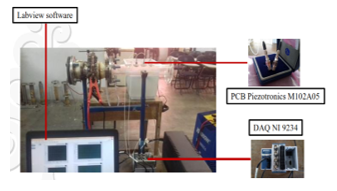 Figure 2: SWTE experiment set-up
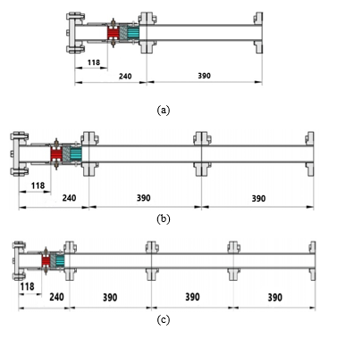 Figure 3: SWTE simulation set-up with a variation of resonator length; a. 390 mm , b. 780 mm , c. 1170 mm length of resonator tube.
The second step is simulation with DeltaEC software to find out the performance of SWTE. The first simulation uses experimental test parameters at a 390 mm resonator length. The experimental data in the first step of the study were used to validate the simulation results in the second step. After the two results between the experiment and the simulation are validated, a simulation program is further developed to predict the performance of the SWTE at variations in the length of 780 mm and 1170 mm as seen in Figure 3.
The display of measurement results using NI 9234 data logger as a simulation parameter that was read by Labview is shown in Figure 4. at point 1 and around 3600 Pa, 138 Hz at point 2. The measurement data from these two pressure sensors are then processed to get the acoustic intensity and acoustic power using equations 3 and 7. The final result for this experiment is the acoustic power of 22,853 watts.
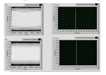 Figure 4: Pressure Amplitude and frequency of SWTE ekperiment result.
4. Result and Analysis
The result of program execution is a schematic SWTE construction diagram with segments of the components used, as presented in Figure 5. It is in a closed on one side state expressed by the SURFACE segment. The other components are Excess pipe, which is stated by DUCT segment, HHX and CHX components are expressed by HX segment, STKSCREEN segments express wire mesh stack, and resonator tube is expressed in DUCT segment.
The DeltaEC program shown in Figure 6 begins by entering the initial parameters as used in the experiment testing, followed by settings for each segment used. In Segment 6 which is the Duct segment for the resonator, a variation of the resonator length of 390 mm is included so that the total power and the acoustic power generated by the SWTE system. The simulation program that has been successfully executed to obtain the performance of SWTE is then used to simulate the performance of SWTE at the length of other resonators. This simulation is done by changing the program simulation parameter at segment DUCT.
The acoustic power that was successfully generated from the simulation for a 390 mm resonator length was 20,13 watts.
The difference in acoustic power between experimental results and simulation results is 3%, so this difference is still acceptable because the value of the deviation is even smaller than 10% [12].
The distribution of acoustic power from the system can be seen from the graph in Figure 7 as a result of program execution. The red line shows the total energy on the device while the blue line is the acoustic power. In the segments 1 and 2, which are bounce space areas, there is no power generation. Acoustic power starts to be generated in the core area of SWTE, and the highest is in the field of stack wire mesh which is almost 30 watts. Momentary out of CHX this power goes down and will tend to be constant along the resonator tube which is around 20 watts. The total power of this system is 680 watts, so the efficiency of SWTE with a resonator length of 390 m is 2.94%.
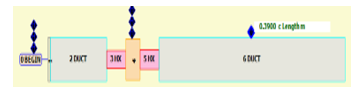 Figure 5: Schematic diagram result of simulation for 390 mm resonator length.
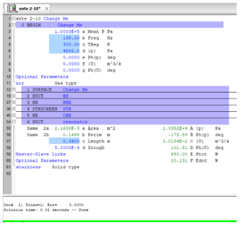 Figure 6: Result simulation of power at 390 mm of resonator length
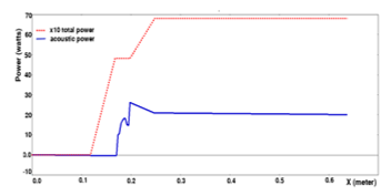 Figure 7: Power distribution of SWTE use 390 mm of resonator length.
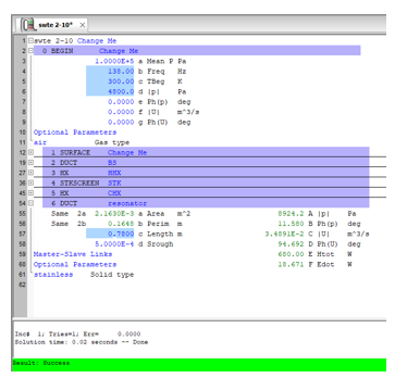 Figure 8: Result simulation of power output at 780 mm of resonator length
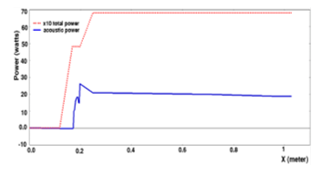 Figure 9: Power distribution of SWTE use 780 mm of resonator length.
Figure 8 to 11 presents acoustic power generated for a resonator length of 780 mm and 1170 mm, respectively. The simulation with a 780 mm resonator length is done by changing the segment 6 in the program by liquefying the other parameters in a fixed condition, as shown in Figure 8. The output power for this condition is 18.67 watts for acoustic power and 680 watts for total power. There was no change in total power due to variations in this second simulation; no other parameters were changed. The efficiency gained from this conditioning system is 2.7%.
As shown in Figure 9, for the length of resonator tube 780 mm at a position of 0 to 0.18 m there is no power generation because a bounce space occupies this position as an air reservoir. At intervals of 0.18 ≤ x ≤ 0.2 m, which is the position of the HHX and stack, the acoustic power starts to rise and reaches the highest value shortly after leaving the stack, which is 26.12 watts. CHX occupies the area at 0.2 ≤ x ≤ 0.4 m intervals, resulting in acoustic power of 20.96 watts. This value is lower than when the stack exits due to water cooling on the CHX side. This value will tend to be constant when passing through the resonator at a distance of 0.4 ≤ x ≤ 1.2 m, which is equal to 18.67 watts.
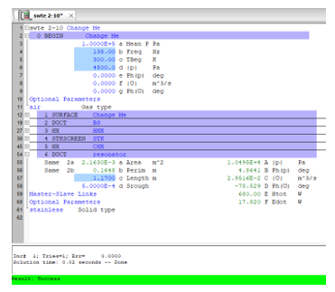 Figure 10: Result simulation of power output at 1170 mm of resonator length
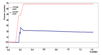 Figure 11: Power distribution of SWTE use 1170 mm of resonator length
The simulation results for the variation of the resonator length of 1170 mm are presented in Figure 10. Like the two previous simulations, segment 6 of the resonator length is changed to obtain information on the amount of output power generated by this system. The results can be seen that the total power produced is still constant at 680 watts because there is no change in the thermoacoustic core parameters. The acoustic power generated is smaller by 17.82 watts so that the efficiency of the system as a result of this third simulation is 2.62%.
The acoustic power distribution as presented in Figure 11 has the same trend with the simulation results for the variation of the resonator lengths of 390 mm and 780 m, where on the bounce space side the end is closed, there is no power generated, the core has the highest value and the resonator will tend to go down until the side open end on this system.
Based on the simulation results for SWTE with variations in the length of the resonator, the results show that the longer the resonator tube, the output power of the system will decrease. The prediction from this simulation is following the research conducted by [9] and [10], namely that the length of the resonator will affect the acoustic power so that it will also affect its efficiency.
The way to increase the standing type of performance can be done by changing to the co-axial type without changing the length of the resonator. Takeyama [17] has tested it by inserting an inner tube into the resonator to the bounce space area. The inner tube used is smaller than the diameter of the resonator tube, as seen in Figure 12. Estimation of co-axial performance can be done by simulations using DeltaEC, such as research by [18] which conducted this simulation to optimize co-axial traveling-wave thermoacoustic cooler powered by the standing-wave thermoacoustic engine.
The simulation results of the co-axial type of thermoacoustic engine which the inner tube diameter of 25 mm and 580 mm length presented in Figure 13. The acoustic power is 30 watts. There was an increase of about 10 watts compared to the SWTE type result in both simulation and experimental. The total energy that can be achieved by co-axial is about 100 watts, so the efficiency of this system is around 3%, slightly higher than the SWTE.
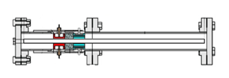 Figure 12: Co-axial thermoacoustic engine contruction.
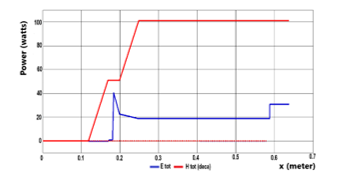 Figure 13: Power distribution of co-axial use 25 mm inner tube diameter
A summary of the comparison of research results in this paper is presented in Table 1
Table 1: Comparison of test results with variations in resonator length
| Methods | Length of Resonator (mm) | Acoustic Power (watts) |
| Experiment | 390 | 22.85 |
| Simulation | 390 | 20.13 |
| Simulation | 780 | 18.67 |
| Simulation | 1170 | 17.82 |
|
Simulation (co-axial) |
390 | 30.00 |
5. Conclusion
Simulations to predict the performance of SWTE open-close have been carried out. Its application for a 390 mm resonator length successfully made, and the results match the experimental data. Execution of other resonator lengths, namely 780 mm and 1170 mm, states that a prolonged resonator reduces the acoustic power produced by this device. Another method for increasing engine performance without changing the length of the resonator is by making the device co-axial type.
Conflict of Interest
The authors declare no conflict of interest.
Acknowledgment
The author would like to thank the Gadjah Mada University Higher Education Research Scheme, which has supported part of this research.
- N. Rott, “Thermoacoustics,” Adv. Appl. Mech., vol. 20, pp. 135–175, 1980. https://doi.org/10.1016/S0065-2156(08)70233-3
- S. L. Garrett, “Thermoacoustic Refrigeration,” Naval Postgraduate School, Breckenridge Hilton, Breckenride CO, 1993.
- G. . Swift, “Thermoacoustic engines,” J. Acoust. Soc. Am., vol. 84, no. 4, pp. 1145–1180, 1988. https://doi.org/10.1121/1.396617
- H. Babaei and K. Siddiqui, “Design and optimization of thermoacoustic devices,” Energy Convers. Manag., vol. 49, no. 12, pp. 3585–3598, 2008. https://doi.org/10.1016/j.enconman.2008.07.002
- G. W. Swift, “Analysis and performance of a large thermoacoustic engine,” J. Acoust. Soc. Am., vol. 92, no. 3, pp. 1551–1563, 1992. https://doi.org/10.1121/1.403896
- I. Setiawan, P. Murti, W. N. Achmadin, A. B. S. Utomo, and M. Nohtomi, “Design, construction and evaluation of a standing wave thermoacoustic prime mover,” in AIP Conference Proceedings, 2016, vol. 1717. https://doi.org/10.1063/1.4943482
- T. Jin, B. Zhang, K. Tang, R. Bao, and G. Chen, “Experimental observation on a small-scale thermoacoustic prime mover,” J. Zhejiang Univ. A, vol. 8, no. 2, pp. 205–209, 2007. https://doi.org/10.1631/jzus.2007.a0205
- K. Tang, G. B. Chen, T. Jin, R. Bao, B. Kong, and L. M. Qiu, “Influence of resonance tube length on performance of thermoacoustically driven pulse tube refrigerator,” Cryogenics (Guildf)., vol. 45, no. 3, pp. 185–191, 2005. https://doi.org/10.1016/j.cryogenics.2004.10.002
- N. M. Hariharan, P. Sivashanmugam, and S. Kasthurirengan, “Influence of stack geometry and resonator length on the performance of thermoacoustic engine,” Appl. Acoust., vol. 73, no. 10, pp. 1052–1058, 2012. https://doi.org/10.1016/j.apacoust.2012.05.003
- A. C. Alcock, L. K. Tartibu, and T. C. Jen, “Experimental investigation of an adjustable standing wave thermoacoustic engine,” Heat Mass Transf. und Stoffuebertragung, vol. 55, no. 3, pp. 877–890, 2018. https://doi.org/10.1007/s00231-018-2469-1
- G. Zhou, Q. Li, Z. Li, and Q. Li, “Influence of resonator diameter on a miniature thermoacoustic Stirling heat engine,” Chinese Sci. Bull., vol. 53, no. 1, pp. 145–154, 2008. https://doi.org/10.1007/s11434-008-0019-9
- G. . Swift, “Thermoacoustics: A Unifying Perspective for Some Engines and Refrigerators,” Leb. und-Technologie, vol. 35, no. 7, p. 636, 2002. https://doi.org/10.1016/s0023-6438(02)90911-4
- Sugiyanto, S. Kamal, J. Waluyo, and A. Widyaparaga, “Simulation of Close-Open Standing Wave Thermoacoustic Engine Toward Variation of Resonator Diameter,” in 4th International Conference on Science and Technology, ICST 2018, 2018, vol. 1, pp. 1–5. https://doi.org/10.1109/ICSTC.2018.8528657
- B. Ward, J. Clark, and G. Swift, Design environment for low-amplitude thermoacoustic energy conversion (DeltaEC), vol. 122, no. 5. 2007. https://doi.org/10.1121/1.2942768
- T. D. Rossing, Springer Handbook of Acoustic. LLC New York: Springer Science+Business Media, 2007.
- T. Biwa, Y. Tashiro, H. Nomura, Y. Ueda, and T. Yazaki, “Experimental verification of a two-sensor acoustic intensity measurement in lossy ducts,” J. Acoust. Soc. Am., vol. 124, no. 3, pp. 1584–1590, 2008. https://doi.org/10.1121/1.2953311
- Y. Takeyama, S. ichi Sakamoto, and Y. Watanabe, “Study on the setting position of a prime mover in the coaxial-type thermoacoustic cooling system: Comparison with the straight-tube-type thermoacoustic system,” Jpn. J. Appl. Phys., vol. 57, no. 7, 2018. https://doi.org/10.7567/JJAP.57.07LE14