
Performances of Thermoelectric Cooling System for Cooling Flowing Water in a Water Block
Volume 4, Issue 5, Page No 268-272, 2019
Author’s Name: Mirmanto Mirmantoa), Yesung Allo Padang, Zefri Ardian
View Affiliations
Jurusan Teknik Mesin, Universitas Mataram, 83125, Indonesia
a)Author to whom correspondence should be addressed. E-mail: m.mirmanto@unram.ac.id
Adv. Sci. Technol. Eng. Syst. J. 4(5), 268-272 (2019); ![]() DOI: 10.25046/aj040533
DOI: 10.25046/aj040533
Keywords: Thermoelectric, Mass flow rate, Water block, COP

Export Citations
This study investigated thermoelectric cooling system performances to cool the water flowing inside a water block. The experiments employed two identical thermoelectrics model TEC2-25408 with an overall dimension of 40 mm x 40 mm x 6.4 mm. The cold side of the thermoelectric was affixed to the top surface of the water block, while the hot side of the thermoelectric was attached to the heat pipe. The mass flow rates of the water were varied, i.e. 1 g/s, 1.5 g/s, and 2 g/s. Calibrated K-type thermocouples with an uncertainty of ± 0.5°C were used for measuring the temperatures. The experiment was observed for about 5 hours. All data were recorded using the data logger DAQ MX 9714 NI that was connected to the PC with the LabView program. The results show that raising the mass stream rate increases the cooling capacity and the COP. However, the effect of the mass stream rate on the water temperature at the outlet is unclear. In general, the thermoelectric has less advantage for cooling flowing water.
Received: 02 August 2019, Accepted: 14 September 2019, Published Online: 08 October 2019
1. Introduction
The cooling system for electronics develops continually in accordance with heat pipe technologies for removing heat rates from CPU. With its compact shape, high heat dissipation, and easy maintenance, the combination of heatsink-heat pipes becomes the right solution to cool the hot side of the thermoelectric module (TEM). The advantages of thermoelectric cooling system (TCS) are: (i) no heavy components, (ii) not noisy, (iii) small and compact, (iv) easy to maintain. However, the system also has disadvantages; e.g. small capacity, low COP (even less than 1) as reported in Ananta et al. [1], Mirmanto et al. [2, 3]. Ananta et al. [1] studied a thermoelectric cooler box for cooling drinking water. The aim of their study was to know the effect of thermoelectric electrical arrangements on the cooler box COP. The TEMs were arranged in parallel and series electrical connections. Meanwhile, Mirmanto et al. [2] investigated the effect of heat dissipation units on the cooler box performances. Nevertheless, they all used the TEMs to cool the water in plastic bottles placed inside the cooler box. The water did not flow at all. Cooling static water (not flowing water) seems to be easy because the water temperature decreases with time.
Different from cooling static water, cooling flowing water is more complex because the inlet water temperature is constant; it does not decrease with time. Therefore, this may need a lot of energy. When the thermoelectric used is just one or two, the water may not get low temperatures at the outlet. The temperature difference between the inlet and outlet is very small. This means that cooling purposes cannot be achieved. Azimi et al. [4] reported that the decreased temperature of flowing water that was cooled using thermoelectric was around 1.2°C. Ahamat et al. [5] cooled the flowing water using TEM with the hot side of the TEM cooled using water. They found their COP was greater than 1, i.e. 4.5. However, the water temperature at the outlet was not revealed. Recently, Ardian [6] conducted an investigation using TEM to cool flowing water inside a water block. He found a similar phenomenon. He obtained the difference in temperature between the inlet and outlet was just only 4°C. Further, studies on the use of TEMs, unfortunately, are still limited. Therefore, not much information can be reviewed.
In general, researches on TEMs that have been done are to cool stationary water; e.g drinking water, water in bottles, water in a tank, stationary air or solid materials. The flowing water or air is usually used to cool the hot side of the TEM; e.g. Jugsujinda et al. [7], Enescu and Spertino [8], Kin et al. [9]. For the above background, this study tries to explore the possibility of TEMs to cool flowing water. The aim of this study is to investigate wheater the TEM is proven able to reduce the temperature of streaming water significantly.
2. Research Method
2.1. Experimental Set-up
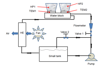 Figure 1: Schematic diagram of the research for cooling flowing water using TEMs, HP is heat pipe, HE is heat exchanger.
To know the ability of the TEM for cooling flowing water, experiments are set as follows. This study uses an experimental method, i.e. testing the research apparatus to obtain data that are required to answer or solve the problem statement. The schematic diagram of the research apparatus is shown in Figure 1. The apparatus consisted of a water block, two TEMs, two heat pipe units, a water pump, a small radiator, a flowmeter, and a small water tank. The material investigated was water flowing in a water block as indicated by Figure 2. The water block dimension was 200 mm x 40 mm x 10 mm, and it was made of aluminum. The water block comprised of 15 fins inside with a thickness of 1 mm. The mass flow rate of the water was varied; e.g. 1 g/s, 1.5 g/s and 2 g/s, and measured using a flowmeter model FL1000 with an accuracy of ± 0.1 g/s. Type K thermocouples, which were calibrated, were used to measure all temperatures and the total numbers of thermocouples employed were 18. The uncertainty of the temperature was ± 0.5°C obtained from calibration. The temperatures were recorded directly using a data logger NI-cDAQ9174 so that all temperatures were recorded simultaneously. Meanwhile, the power supplied to the TEMs was of approximately 82.2 W.
Two TEMs model TEC2-25408 were utilized in this study. They were installed on the water block. The cold side was faced to the water block, while the hot side was stuck on the heat pipe. Further, the water block was also insulated using an aluminum foil sponge. The heat rate from the water block was absorbed by the cold side of the TEMs, and then it was thrown away to the heat pipe on the hot side of the TEMs. The heat pipes employed were double fan heat pipe because each heat pipe had two fans. The photograph of the heat pipes installed and the dimension of the water block is shown in Figure 2.
Water was circulated throughout the test rig using a small pump. From the tank, water flowed to the flowmeter. Before passing through the flowmeter, the mass flow rate of water was adjusted using valves 1 and 2. Using this adjustment, the water mass flow rate could be controlled and suited. From the flowmeter, water then flowed to the water block, where two thermoelectrics were installed. The temperature of water decreased after passing the water block, and then water streamed to the heat exchanger. In the heat exchanger, the water gained heat again and the water temperature increased. From the heat exchanger, the water returned to the tank, and circulated again and so on.
2.2. Data Analysis
Analyzing experimental data can only be performed after some experiments are conducted. Data that are analyzed are temperatures, mass flow rates and power given to the TEMs. The data are analyzed using some equations that have been available in the published papers or books. From the analysis, some dependent variables are obtained and known; e.g. Qc, Qh, P, and COP. Then from these variables, a conclusion can be made. The conclusion will give us information about whether the TEM is potentially used to cool the flowing liquid or not.
In the use of Peltier principles, one side of the TEM becomes hot and the other becomes cool. The hot side temperature of the TEM can be estimated using equation (1) that can be found in Mirmanto et al. [3], Jugsujinda et al. [7], Abdul-Wahab et al. [10], Wahyu [11].
![]() Th is the hot side temperature of the TEM (°C), T∞ represents the ambient temperature (°C), ϴ is the thermal resistance of the TEM (°C/W) and Qh is the heat rate (w) that is released by the hot side of the TEM.
Th is the hot side temperature of the TEM (°C), T∞ represents the ambient temperature (°C), ϴ is the thermal resistance of the TEM (°C/W) and Qh is the heat rate (w) that is released by the hot side of the TEM.
The temperature difference between the cold side and the hot side of the TEM, ∆T, can be obtained using equation (2). This equation is adopted from [2, 3, 7, 10] and Mani [12].
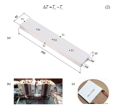 Figure 2: Water block and heat pipe; (a) positions of the thermocouples on the water block (unit in mm and without scaling), (b) double fan heat pipe installed on the water block, (c) TEM type TEC2-25408, Ardian [6].
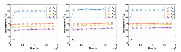 Figure 3: Relationship between temperatures and time; (a) 1 g/s, (b) 1,5 g/s, (c) 2 g/s. Tc: is cold side temperature of TEM, Th: hot-side temperature of the TEM dan Twb: average water block temperature.
![]() ṁ is the water mass flow rate (kg/s), cp is the specific heat (J/kg°C ), and ΔTf is the difference in temperature of the water, which is equal to the inlet temperature minus the outlet temperature at the water block (°C). cp is determined using bulk temperature. The bulk temperature is equal to (Ti + To)/2 as suggested by Incropera et al. [16].
ṁ is the water mass flow rate (kg/s), cp is the specific heat (J/kg°C ), and ΔTf is the difference in temperature of the water, which is equal to the inlet temperature minus the outlet temperature at the water block (°C). cp is determined using bulk temperature. The bulk temperature is equal to (Ti + To)/2 as suggested by Incropera et al. [16].
The electrical power supplied to the TEM can be estimated using equation (5), and it can be obtained in Incropera et al. [16], Cengel and Boles [17].
![]() Th is the hot side temperature (°C) and Tc is the cold side temperature (°C). The relationship between heat rate of hot and cold sides of the TEM can be expressed by equation (3). This equation was taken from [1-3, 12].
Th is the hot side temperature (°C) and Tc is the cold side temperature (°C). The relationship between heat rate of hot and cold sides of the TEM can be expressed by equation (3). This equation was taken from [1-3, 12].
![]() Qc is the heat rate of the cold side of the TEM (W), and P is the DC electrical power given to the TEM (W). Equation (3) was also used by Nugroho [13], and Ramdhan [14]. Qc is also called a cooling load/ capacity that can be predicted using equation (4). This equation can be found in Holman [15], and Ardian [6].
Qc is the heat rate of the cold side of the TEM (W), and P is the DC electrical power given to the TEM (W). Equation (3) was also used by Nugroho [13], and Ramdhan [14]. Qc is also called a cooling load/ capacity that can be predicted using equation (4). This equation can be found in Holman [15], and Ardian [6].
P is the electrical power (W), V is the voltage (V), and I is the current (A). The voltage and current can be measured directly using a multitester. Meanwhile, the performance, which is noted by COP, can be predicted by equation (6), which was taken from Jugsujinda et al. [7]. The COP of the TEM usage is smaller than the COP of the compression refrigeration system as revealed in Wang et al. [18].
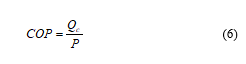 COP is the Coefficient of performance.
3. Results and Discussion
This study aims to cool water using a TEM with a heat pipe as the heat dissipation unit. The heat pipe is chosen because of the previous research has shown that the heat pipe can remove much heat rate compared to a heat sink with a fan as reported in Anggani [19]. The results of recording temperatures are shown in Figure 3.
Figure 3 indicates temperatures Tc and Twb. Tc and Twb increased drastically at just after a second. After a few seconds, they become flat or even sometimes they increased. They increased because the room used for conducting experiments was not conditioned. When the ambient temperature increased, the temperatures of water and water block increased too. This actually indicated that the TEM could not absorb much heat from the water block containing flowing water. The TEM seemed not able to resist the small change in the ambient temperature. Meanwhile, the temperature of the hot side of the TEM increased drastically after a second and then it became constant. In Figure 3, the effect of mass flow rate on Tc is significant. The recorded Tc is presented in Table 1. Mass flow rate increases, Tc and Twb also increase. This indicates that at higher water mass flow rates, the TEM cannot decrease the outlet temperature at the water block exit. This phenomenon is really different from the thermoelectric cooling system performance for cooling stationary water. Cooling the stationary water could have lower temperatures, e.g. 13°C as reported in [2, 3], and Mirmanto et al. [20]. Furthermore, at around the initial time of running the machine, Tc and Twb decreased sharply while Th increased drastically. This was due to the character of the TEM. When the current flowed to the TEM, the cold and hot sides of the TEM suddenly changed. The cold side became cold abruptly, and the hot side became hot rapidly. However, after a moment, the heat transfer equilibrium took place, so that all temperature became constant or sometimes they raised due to the increase in ambient temperatures.
As shown in Table 1, Tc raised with an increase in mass flow rates. The temperature difference for each other was almost 1°C. This phenomenon was due to the constant power of the TEM. The power of the TEM affected greatly the capability of the TEM to absorb heat. Therefore, when the cooling load increased due to the rise in the mass flow rate, Tc elevated because the cold side of the TEM was no longer able to transfer heat. This was also found by Mirmanto et al. [20]. Nevertheless, Tc influenced the room and water temperatures inside the cooler box. When Tc increased, the room and water temperatures raised as reported in [20]. In this study, when Tc elevated, the average water block also increased as shown in Figure 3.
Table 1: Recorded Tc at several mass flow rates
| Time | Tc (°C) | ||
| (s) | at 1 g/s | at 1.5 g/s | at 2 g/s |
| 0 | 28.26 | 28.15 | 28.04 |
| 1800 | 19.43 | 20.57 | 22.85 |
| 3600 | 20.36 | 21.12 | 23.26 |
| 5400 | 20.82 | 21.56 | 23.31 |
| 7200 | 20.94 | 21.96 | 23.85 |
| 9000 | 21.23 | 22.44 | 23.78 |
| 10800 | 21.31 | 22.35 | 24.03 |
| 12600 | 21.41 | 22.34 | 23.91 |
| 14400 | 21.38 | 22.66 | 24.06 |
| 16200 | 21.39 | 22.95 | 24.20 |
| 18000 | 21.69 | 23.18 | 24.04 |
To analyze the ability of the TEM further, Figure 4 is presented. Figure 4 indicates the relationship between Qc and time at several water mass flow rates. Figure 4 demonstrates that Qc is constant with time. However, increasing the water mass flow rate elevates Qc. This is suitable for the theory of Holman [15] or agrees with equation (4). The outlet temperature, To, decreased drastically at a few seconds, but then it increased gradually. This was due to the effect of ambient temperature. The research was started in the morning at 08.00 am and finished in the afternoon at 01.00 pm. Therefore, the ambient temperature increased, and consequently, the outlet water temperature, To, increased. Figure 5 shows the outlet water temperature, To. The effect of water mass flow rates on the outlet water temperature is unclear. The lines of outlet temperatures are touching each other at the uncertainty of ± 0.5°C. This could be due to the fluctuation of To. To and other temperatures were affected by the ambient temperature, therefore, To fluctuated depending on the ambient temperature.
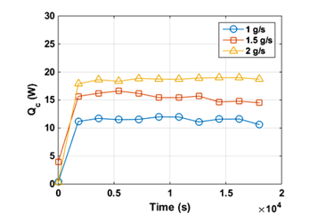 Figure 4: Relationship between Qc and time at several mass flow rates of water
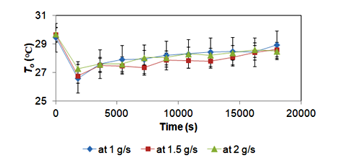 Figure 5: Relationship between To and time at several mass flow rates of water.
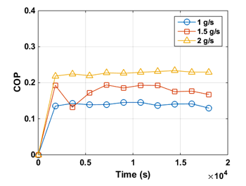 Figure 6. Relationship between COP and time at several mass flow rates of water
Another variable examined in this study is COP. The experimental COP is presented in Figure 6. COP indicates the performance of the cooler box, i.e. cooling capacity divided by power supplied to the TEM (or system) as expressed by equation (6). The power supplied to the TEM is calculated using equation (5). The calculated COP is given in Figure 6 at the three different mass flow rates. Similar to the cooling capacity’s trend, COP increases drastically and then it gets persistent. This phenomenon occurs for the three mass flow rates. In Figure 6, it is clear that COP is affected by the mass flow rate. As the mass flow rate raises, COP elevates. This can happen due to increased cooling capacity, while the power supplied to the TEM is constant. This phenomenon was also found by Ramdhan [14], Mirmanto et al. [20]. Nevertheless, they used the cooler box for cooling water in plastic bottles. Their COP increased with an increase in the water volume. Further, COP obtained in this study and by Ramdhan [14] and Mirmanto et al. [20] is still lower than 1.
4. Conclusion
Experiments have been done to investigate the ability of the TEM to cool the flowing water. The TEMs used were two pieces with the electrical power of 82.2 W and the mass flow rates of the water employed were 1 g/s, 1.5 g/s, and 2 g/s. Some findings are as follows:
- In general, the trend of the temperature in accordance with the results obtained by the previous researchers.
- The effect of the mass flow rate on the cooling capacity is clear. Increasing the mass flow rate elevates the cooling capacity.
- The effect of the mass flow rate on the outlet temperature is unclear.
- The temperature of the water block elevates as the mass flow rate increases. The minimum temperature of the cold side of the TEM at 1 g/s is 19.43°C, at 1.5 g/s is 20.57°C and at 2 g/s is 22.85°C.
- COP raises with the increase in mass flow rate.
- The water temperature is affected greatly by the ambient temperature.
- Cooling flowing water using TEC is not powerful. The TEM is better to be used for cooling the stationary liquid.
Conflict of Interest
The authors declare no conflict of interest.
Acknowledgment
On this occasion, the authors would like to acknowledge the DRPM of the Indonesian Ministry of Research and Technology and Higher Education for the funding through the research scheme PDUPT 2019, with the contract number: 1842/UN18.L1/PP/2019. Also, the authors thank the Department of Mechanical Engineering, Mataram University for the facility.
- H. Ananta, Mirmanto, Y.A. Padang, “Unjuk Kerja Kulkas Termoelektrik dengan Rangkaian Seri dan Parallel pada Beban Air 1500 ml” Dinamika Teknik Mesin, 7(2), 80-86, 2017.
https://doi.org/10.29303/dtm.v7i2.157 - Mirmanto, I.B. Alit, I.M.A. Sayoga, R. Sutanto, Nurchayati, A. Mulyanto, “Experimental cooler box performance using two different heat removal units: a heat sink fin-fan, and a double fan heat pipe” Frontier in Heat and Mass Transfer, 10(34), 1-7, 2018.
http://dx.doi.org/10.5098/hmt.10.34 - M. Mirmanto, S. Syahrul, Y. Wirdan, “Experimental performances of a thermoelectric cooler box with thermoelectric position variations” Engineering Science and Technology, an International Journal, 22, 177–184, 2019.
https://doi.org/10.1016/j.jestch.2018.09.006 - M. Azimi, S.S. Mirjavadi, M. Sedighi, “A novel cooling system design for water block in liquid cooling garment” Journal of Science and Engineering, 07 (01), 072-082, 2016.
- M.A. Ahamat, R. Abidin, S.M. Abdullah, “Performance of thermoelectric module as a water cooler and water heater” International Journal on advanced science engineering Information Technology, 6(4), 524-528, 2016.
- Z. Ardian, “Sistem Pendinginan Coolant Menggunakan Termoelektrik dengan Unit Pembuang Panas Heat Pipe,” Skripsi, Jurusan Teknik Mesin, Fakultas Teknik, Universitas Mataram, Mataram, NTB, 2018.
- S. Jugsujinda, A. Vora-ud, T. Seetawan, “Analysing of thermoelectric refrigerator performances” Procedia Engineering, 8, 154-159, 2011. https://doi.org/10.1016/j.proeng.2011.03.028
- D. Enescu, F. Spertino, “Applications of hybrid photovoltaic modules with thermoelectric cooling” Energy Procedia, 111, 904-913, 2017. https://doi.org/10.1016/j.egypro.2017.03.253
- L.K. Kin, A.T. Baheta, K. Habib, “Analytical investigation of thermoelectric performance for cooling application” Journal of Advanced Research in Fluid Mechanics and Thermal Sciences, 46(1), 32-40, 2018.
- S.A. Abdul-Wahab, A. Elkamel, A.M. Al-Damkhi, I.A. Al-Habsi, H.S. Al-Rubai’ey’, A.K. Al-Battashi, A.R. Al-Tamimi, K.H. Al-Mamari, M.U. Chutani, “Design and experimental investigation of portable solar thermoelectric refrigerator” Renewable Energy, 34, 30-34, 2009. https://doi.org/10.1016/j.renene.2008.04.026
- D. Wahyu, “Pendingin Minuman Bercatu Daya Termoelektrik,” Skripsi, Jurusan Teknik Mesin Politeknik Negeri Padang, Padang, 2016.
- P.I. Mani, “Design, Modeling and Simulation of a Thermoelectric Cooling System (TEC),” Mechanical and Aerospace Engineering Western Michigan University, USA, 2016.
- W. Nugroho, “Rancang Bangun Alat Pendingin Minuman Portable Menggunakan Peltier,” Skripsi, Jurusan Teknik Mesin Universitas Muhammadiyah Pontianak, Kota Pontianak, 2017.
- G. Ramdhan, “Sistem Pendinginan pada Kulkas Termoelektrik dengan Variasi Pembebanan,” Skripsi, Jurusan Teknik Mesin, Fakultas Teknik, Universitas Mataram, Mataram, NTB, Indonesia, 2016.
- J.P. Holman, Heat Transfer, 8th Edition, McGraw-Hill Companies, Inc., USA, 2002.
- F. Incropera, D.P. DeWitt, T.L. Bergman, A.S. Lavine, “Fundamentals of Heat and Mass Transfer, 6th Edition, John Wiley & Sons, Hoboken, 2006.
- Y.A. Cengel, M.A. Boles, “Thermodynamics an Engineering Approach”, 6th Ed., McGraw-Hill Higher Education, Boston, 2008.
- Z. Wang, J. Zhang, Y. Liu, “A Practical Method for Measuring Thermal Conductance and Cooling Power of Thermoelectric Modules,” Tinajing Institute Of Power Sources, China, 2001.
- Y. Anggani, “Peningkatan Peforma Kulkas Termoelektrik Dengan Menggunakan Heat Pipe Sebagai Unit Pembuang Panas,” Skripsi, Jurusan Teknik Mesin Fakultas Teknik Universitas Mataram, Mataram, Indonesia, 2018.
- M. Mirmanto, I.W. Joniarta, I.M.A. Sayoga, N. Nurpatria, Y.A. Padang, I.G.N.K. Yudhyadi, “Effect of Water Volume on a Thermoelectric Cooler Box Performance” Frontiers in Heat and Mass Transfer, 11(17), 1-9, 2018. http://dx.doi.org/10.5098/hmt.11.17