
The Impact of Using Upgraded Biogas on Generator Performance
Volume 4, Issue 5, Page No 186-192, 2019
Author’s Name: Wilson Babu Musinguzia), Ibrahim Luqman Mpungu
View Affiliations
Department of Mechanical and Manufacturing Engineering, Faculty of Engineering, Kyambogo University, P.O. Box 1 Kampala, Uganda
a)Author to whom correspondence should be addressed. E-mail: Wilson.Musinguzi@gmail.com
Adv. Sci. Technol. Eng. Syst. J. 4(5), 186-192 (2019); ![]() DOI: 10.25046/aj040524
DOI: 10.25046/aj040524
Keywords: Upgraded Biogas, Thermal Characterization, Efficiency

Export Citations
This research focussed on assessing the impact of using upgraded biogas from chicken waste on the performance of a gasoline generator. In the study, the characteristics of raw biogas were determined and a biogas upgrading device was developed before assessing the generator performance on upgraded biogas. A Geotech GA 2000 plus gas analyser was used for biogas characterization and a slightly modified Elemax SH 2900 gasoline generator (5 HP) was used. The findings revealed that biogas from chicken waste comprised of 57% CH4 and 41% CO2 with small amounts of H2S, O2 and NH4. During biogas upgrading, the highest solvent to biogas flow rate used was 0.80. NaOH excelled with 93.0% CO2 reduction followed by KOH at 82.5% and lastly water at 63.0%. Using upgraded biogas improved the generator’s brake thermal efficiency from 14.2% for raw biogas to 17.6% for upgraded biogas. A locally fabricated scrubbing device significantly upgraded the biogas quality.
Received: 27 April 2019, Accepted: 13 September 2019, Published Online: 08 October 2019
1. Introduction
Biogas is a renewable energy gaseous fuel produced from anaerobic digestion of biological wastes such as cattle dung, vegetable waste, sheep, poultry droppings, municipal solid waste, industrial waste water, land fill, etc. in the absence of oxygen and the presence of anaerobic microorganisms [1]. The process is achieved at elevated temperature range of 30 to 60oC. The produced biogas comprises of mainly methane (CH4) and carbon dioxide (CO2) with smaller amounts of hydrogen sulphide (H2S) and ammonia (NH4). Biogas is an excellent fuel for a large number of applications including production of heat and steam, electricity production, vehicle fuel and production of chemicals. In Uganda, the most common applications for biogas are cooking and lighting. Conventional gas burners and gas lamps can be modified to suit biogas by changing the air to gas ratio.
In this study, Okweru Poultry Farm was used as a case study. Apparently, biogas from chicken droppings was being used for lighting the chicken houses, heating the brooder and cooking by the farm workers. The researchers explored alternative uses for the biogas produced with focus on electricity generation using a gasoline generator.
Although biogas can be used as a fuel, it has an extremely low energy density on volume basis. This is because of the presence of CO2 at higher quantities that reduce its calorific value, flame velocity and flammability range compared with other fuels [2]. The high CO2 levels in biogas can be lowered through biogas upgrading. Global upgrading technologies include: absorption, membrane, absorption and cryogenic technology. Applying these techniques to small scale biogas plants presents complexity and high costs of investment. This leads to utilization of biogas without upgrading for basic applications in developing countries.
The utilization of biogas in stationary engines is a typical case where contaminants have to be removed for better performance. In dual fuel operation, increasing the ratio of biogas increases the brake specific fuel consumption while decreasing brake thermal efficiency and the brake engine power of a Compression Ignition (CI) engine [3]. It was reported in [4] that an improved thermal efficiency from 26.2% to 30.4%, when there is 21% reduction of CO2 in biogas used in a Spark Ignition (SI) operation while a 15% CO2 decrease in the biogas increased the thermal efficiency to 22% for dual fuel operations. However, there are other factors that influence the performance of a gas engine.
Various factors responsible for the low thermal efficiency of engines run on biogas were reported in [2]. These include; the long pilot ignition delay and high self-ignition temperature of biogas. These factors delay the fuel combustion process while the low burning velocity due to presence CO2 leads to incomplete combustion. This increases the brake specific energy consumption and exhaust gas temperature of dual fuel modes.
This research aimed at ascertaining the performance improvement of a generator when upgraded biogas was used. This was carried out by analysing the characteristics of raw biogas and later developed a biogas upgrading unit. The performance of a generator was done using Model Elemax SH 2900 gasoline generator. Biogas upgrading reduces the levels of CO2 which improves the burning velocity and calorific value of the gas among others. Through several experiments, the generator brake power output, brake specific fuel consumption and brake thermal efficiency were tested at different load profiles.
2. Materials and Methods
The experimental research included the determination of the biogas characteristics, biogas upgrading device design, fabrication and testing. Also experiments to assess generator performance were carried out for both raw and upgraded biogas. This yielded the primary data utilized in the analysis.
2.1. Characteristics of Raw Biogas
In line with biogas characterisation, a Geotech GA 2000 plus Gas Analyser was used to measure the percentage composition of the biogas constituents. The biogas pressure was measured in kPa using a pressure gauge while a thermocouple was employed for temperature measurement in degrees Celsius. The gas flow rate was measured in litres/minute using an Omega HHF11A Air flow meter.
2.2 Designing the Biogas Upgrading Device
The factors that influence the upgrading process include the dimension of the scrubbing tower, gas pressure, raw biogas composition, water flow rate and purity of the water in use. According to [5], it is possible to produce high quality CH4 enriched gas from biogas by chemical absorption, where a packed bed column and bubble column are used to provide liquid to gas contact.
Therefore, a low-cost upgrading system was designed to receive raw biogas from the bottom and force it through packed marbles to reduce its CO2 content. According to [6], for purification, the height to diameter ratio should be in the range 10:1 to 130:1. For experimental purposes, a device of height to diameter ratio of 10:1 was made and utilized in this study. Based on recommendations by [7], the column was divided into three parts. The top part is half the height of the bottom part while the middle part contains the packing. Marbles were used as packaging material and they occupied 70% of the column height. Based on the data above, the upgrading device was designed with dimensions as shown in Figure 1 while Figure 2 shows the assembly of the device.
2.3 Generator Performance
In internal combustion engines, the combustion of a fuel occurs with an oxidizer (usually air) in a combustion chamber that is an integral part of the working fluid flow circuit [2]. Petrol engines can run fully on biogas whereas diesel engines require combination of biogas and diesel. In the diesel engine, the primary gaseous fuel is inducted with air into the engine cylinder and a small amount of diesel, called pilot fuel is injected for promoting combustion [8].
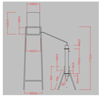 Figure 1: Design of the upgrading device (units in mm)
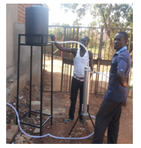 Figure 2: Assembly of the biogas purification device
To assess the generator performance, an Elemax SH 2900 gasoline generator was used. Elemax SH 2900 generator was used because it has a spark ignition engine which can easily ignite the biogas using the spark plug unlike compression ignition engines. Therefore, biogas could be used as a fuel without blending it as it is with compression ignition engines. Table 1 gives the generator specifications.
The gasoline generator was slightly modified to enable it run on biogas. This was done by inserting a wooden piece holding a 10mm metal duct in between the generator engine and carburettor. This duct was to direct biogas to the generator engine without necessarily changing its entire make-up. Therefore, as the generator run, the fuel could be swiftly changed from gasoline to biogas.
Table 1: Elemax SH 2900 Generator Specifications
| S/N | Parameter | Specification |
| 1 | Model | Honda GX160 SH 2900 Generator |
| 2 | Engine type | 4-stroke OHV |
| 3 | Rated power | 3.6 kW @ 3600rpm |
| 4 | Cooling system | Air cooled |
| 5 | Ignition system | Transistorized magnets |
| 6 | Generator AC output | 2400VA @ 220V, 50Hz |
During experiments, biogas was collected in a polythene bag of capacity 1m3. The generator was manually started on petrol and later biogas introduced. The supply of petrol was deliberately and steadily reduced as biogas was steadily introduced while regulating the air intake. Eventually, petrol was completely cut off and the generator ran on biogas. The experimental setup is shown in Figure 3.
The experiments were conducted under different loading conditions. Compact fluorescent lamps were used as the test loads. These test loads were grouped in percentage of the total load which was made of 16 lamps connected in series and parallel. Test load one comprised of 25% of the total load, load two was made of 50% while loads three and four were made of 75% and 100% of the total load respectively.
For each test load, various measurements were taken after stabilization. These include; current, voltage and fuel consumption. An ammeter connected in series was used for current measurement while a voltmeter connected in parallel with the test load was used for voltage measurement. Current was measured in amps while voltage was measured in volts. An air flow meter was used to measure the biogas flow for a given period of time. The results were used to determine the biogas fuel consumed by the generator for each test load given the period it was run. A ball valve connected to the pipe on the biogas bag was used to control the flow rate. The results obtained for each test load were used in calculation of Brake Power, Brake Specific Fuel Consumption (BSFC) and Brake Thermal Efficiency (BTE), using the formulae obtained from [2].
Engine brake power output (Pb):
 Where LHV: Lower Heating Value of the gas.
Table 2 below shows the thermal content of biogas that was considered when calculating the Brake Thermal Efficiency. Since CH4 is the only combustible gas in biogas, it was used when considering the lower heating value of the gas. From the biogas characterization done and the results obtained from the upgrading process, the heating values of biogas were obtained from Table 2 below based on their CH4 content.
Table 2: Methane Yield from Animal Waste [9]
|
Animal |
Typical experimental yield/kg manure |
CH4% |
CO2% |
Thermal content MJ/m3 |
| Cattle | 200 – 350 L | 57.5% | 46.5% | 23 |
| Poultry | 550 – 650 L | 70.0% | 30.0% | 28 |
| Pig | 400 – 500 L | 65.0% | 35.0% | 26 |
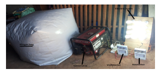 Figure 3: Experimental Setup for the Generator Running on Biogas
3. Results and Discussions
3.1 Characterization of Biogas from the Digester
Biogas from chicken droppings was got from a 30m3 Fixed Dome Digester. It comprised of 57.3% CH4, 41.6% CO2, 0.2% O2, 332 ppm of H2S and a balance of 0.4%. These were read at a digester temperature of 28.1oC, pressure of 16kPa and maximum flow rate of 15litres/minute. Biogas from poultry wastes can comprise 70% CH4 (Abdul Kareem, 2005). However, the variations exhibited can be attributed to numerous factors including the operating temperature of the digester, level of substrate mixing, the pH, carbon to nitrogen ratio (C:N) and toxins in the feedstock which may be as a result of the vaccines administered to the chicken. Biogas production can be increased by operating the digester at thermophilic temperature ranges. The said digester was run at mesophilic temperature ranges expected to be between 25-35oC. Factors such as, optimum substrate mixing, neutral pH and optimum C: N ratios can affect the biogas yield quantities and component distribution.
3.2 Experimental Results obtained from the designed Biogas Upgrading Device
To establish the performance of the fabricated apparatus, different experiments were carried out to determine the device efficiency. This was done using three solvents including; H2O, NaOH and KOH. At solvent to biogas flow rates of 0.20, 0.40, 0.60 and 0.80, the data captured was relating to biogas composition, CH4 enrichment and CO2 reduction. The comparative data obtained for analysis of the three solvents using average values is given in Table 3. The findings in table 3 indicate that at the same ratio of solvent to biogas flow rate, the CO2 reduction was lowest for water, followed by KOH and highest for NaOH. On the other hand, the same ratios of the flow rate for the solvent to biogas, highest CH4 enrichment was generated in NaOH, followed by KOH and lowest for H2O. This is because solutions of NaOH and KOH have enhanced scrubbing capabilities for CO2 removal. Figure 4 illustrates the percentage CH4 enrichment using the various solvents at varying flow rate ratios.
Graphically, for the three solvents, best performance was exhibited at a ratio of NaOH to biogas flow rate of 0.80 where CO2 reduction clocked 93% and the CH4 enrichment level was 60.6%. The device thus performed better at higher flow rate ratios of 0.80 than at low flow rate ratios of 0.20 for all solvents. This is because there is more CO2 absorption when the volume of solvent interacting with a given biogas volume is relatively high. Although better results are obtained at high flow rates, further increasing flow rate led to flooding of the device. Higher columns can properly cater for higher flow rates hence delaying flooding. The height of the column can be technically increased by packing. Packaging materials greatly increase the surface area of the column and hence interaction time of the gas and solvent thereby delaying flooding. Packaging further allows for efficient contact between the water (solvent) and gas phases in a counter current absorption process [7]. It is recommended that almost 70% of the column height should be filled with packaging material for good results [10]. However, the kind of packaging material defines the impact on the performance of the column. This is because packaging material affects the uniform distribution of the solvent and biogas as they flow across the column cross section.
3.3 Characteristic Generator Performance
Having developed and tested the performance of the biogas upgrading unit, control experiments were conducted to establish the performance of biogas in electricity generation. This was done by replacing the generator fuel from gasoline with biogas. Both raw and upgraded biogas was used and varying results were obtained.
3.3.1. Experimental Results of the Generator Performance on Raw Biogas
In this experiment, raw biogas was used in the generator. Ammeter, voltmeter and flow meter readings were recorded and used in Formulae 1 to 3, used to come up with data in Table 4. From the biogas characterization done, the CH4 content was recorded at 57.3%. Therefore, the heating value of the raw gas was assumed to be 23MJ/m3 or 20MJ/kg as earlier noted in Table 2.
3.3.2 Experimental Results of the Generator Performance on Upgraded Biogas
In this set of experiments, biogas was upgraded before it was used in the generator. After the biogas upgrading process, the CH4 content was enriched to 78% using plain water as the solvent at water to gas flow rate ratio of 0.80. Therefore, the heating value of the upgraded biogas was assumed to be 28MJ/m3 or 24.3MJ/kg since it had a higher CH4 content than that quoted for poultry wastes with 70% CH4 in Table 2. Ammeter, voltmeter and flow meter readings were recorded and used in Formulae1 to 3, and used to come up with data in Table 5. From Figure 5, the highest brake power is achieved at 100% loading of the generator with upgraded biogas recorded at 0.239 kW while the lowest brake power was attained at 25% electric load with raw biogas recoded at 0.060 kW. The current consumed increases with increase in the connected load. Therefore, the more loads connected, the higher the current consumed and hence an increase in brake power. This is in line with [2] where it is stated that increase in loading increases the combustion quality of the fuel and hence the power output of the generator. This is because the generator output depends on its fuel burning efficiency. From Figure 6, Brake Specific Fuel Consumption (BSFC) decreased with percentage electric load. This was because BSFC decreases with increase in electric load as it depends on fuel consumption directly and brake power inversely which increases with increase in brake load [2]. BSFC is higher for raw biogas at 2.07 kg/kWh as compared to that of upgraded biogas at 1.45 kg/kWh. This is because a larger volume of biogas was required for the same load for raw biogas than for upgraded biogas.
Upgraded biogas had a higher calorific value of 24.3 MJ/kg due to the high CH4 content of 78% and hence the less volume of biogas required for the same load. It is well known that the calorific value of the fuel has an impact on the amount of fuel required for running the engine. On the other hand, Brake Thermal Efficiency (BTE) of upgraded biogas is higher than that from raw biogas. This is because a drop of CO2 in biogas for dual fuelling increases the thermal efficiency. The highest value of upgraded biogas BTE was 17.6% compared to 14.2% of raw biogas and the lowest value for upgraded biogas was 10.2% as compared to 8.7% of raw biogas. BTE increases with increase in brake power. It can be noticed from Figure 6 that BTE increased with increased load. This is the same pattern demonstrated by brake power in Figure 5 since it’s directly proportional with the percentage load. BTE further depends on brake power, fuel consumption rate and calorific value of biogas. Since upgraded biogas had a higher calorific value of 24.3MJ/kg compared to raw biogas’ 20 MJ/kg and lower fuel consumption, it greatly contributed to the higher efficiency of upgraded biogas.
Table 3: Comparison of the Three Solvents on CH4 Enrichment and CO2 Reduction
| Flow Rate Ratio | H2O | KOH | NaOH | |||
| CH4 enrichment | CO2 reduction | CH4 enrichment | CO2 reduction | CH4 enrichment | CO2 reduction | |
| 0.2 | 18.3 | 42.8 | 26.4 | 54.8 | 43.5 | 76.4 |
| 0.4 | 23.2 | 48.6 | 34.0 | 65.4 | 51.1 | 84.9 |
| 0.6 | 30.7 | 58.7 | 40.1 | 72.8 | 57.6 | 91.8 |
| 0.8 | 36.8 | 63.0 | 48.9 | 82.5 | 60.6 | 93.0 |
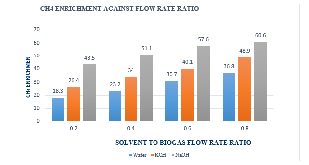 Figure 4: Comparison of the Three Solvents on CH4 Enrichment
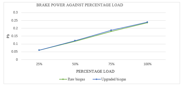 Figure 5: Variation of Brake Power against Percentage Load for both Raw and Upgraded Biogas
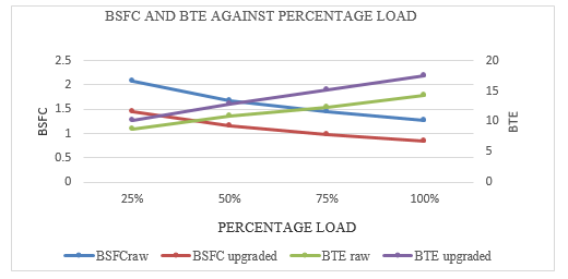 Figure 6: Variation of Brake Specific Fuel Consumption and Thermal Efficiency with Percentage Load
Table 4: Generator Performance on Raw Biogas
| S/N | ELECTRIC LOAD | 25% | 50% | 75% | 100% |
| 1. | Voltage (V) | 222.2 | 227 | 226.3 | 223.8 |
| 2. | Current (A) | 0.27 | 0.52 | 0.80 | 1.05 |
| 3. | Pb (kW) | 0.060 | 0.118 | 0.181 | 0.235 |
| 4. | Fuel consumption (kg/h) | 124.1 | 197.3 | 264.9 | 297.9 |
| 5. | BSFC (kg/kWh) | 2.07 | 1.67 | 1.46 | 1.27 |
| 6. | BTE (%) | 8.7 | 10.8 | 12.3 | 14.2 |
Table 5: Generator Performance on Upgraded Biogas
| S/N | ELECTRIC LOAD | 25% | 50% | 75% | 100% |
| 1. | Voltage (V) | 225.9 | 232.7 | 235 | 227.6 |
| 2. | Current (A) | 0.27 | 0.52 | 0.80 | 1.05 |
| 3. | Pb (kW) | 0.061 | 0.121 | 0.188 | 0.239 |
| 4. | Fuel consumption (kg/h) | 88.6 | 140.0 | 183.2 | 201.2 |
| 5. | BSFC (kg/kWh) | 1.45 | 1.16 | 0.97 | 0.84 |
| 6. | BTE (%) | 10.2 | 12.8 | 15.2 | 17.6 |
During the start of experiments, the generator was run on petrol to heat up and later biogas introduced. This was because it was hard burning biogas at the generator start due to the high heating temperatures required. However, this wasn’t the case when the generator had been running because the generator would have heated up already. This further highlighted the impact of biogas’ low heating value. BTE increases with increased load due to increase in combustion zone temperature. Increase in load increases the combustion zone pressure and heat release rate. This improves the fuel combustion quality hence increasing the power output of the generator. Therefore, the higher the generator power output, the better the BTE.
4. Conclusion
The performance of the biogas upgrading device not only depends on the biogas flow rate but also depends on the dimensions of the scrubbing tower, biogas pressure, packaging material and purity of the water (solvent) used in the process. Upgraded biogas had a higher calorific value of 24.3 MJ/kg due to the high CH4 content of 78% and hence the less volume of biogas required for the same load. Increase in load increases the combustion zone pressure and heat release rate. This improves the fuel combustion quality hence increasing the power output of the generator. Therefore, the higher the generator power output, the better the BTE. Using upgraded biogas improved the generator’s brake thermal efficiency from 14.2% for raw biogas to 17.6% for upgraded biogas.
Conflict of Interest
The authors declare that although they may have conferred with others in carrying out the research and preparation of this paper, and drawn upon the range of sources cited in this work, this paper is their original piece of work and has not been published in any other journal.
Acknowledgment
The authors gratefully acknowledge the funding and support received from RELOAD, a Germany organization dedicated to finding solutions to post-harvest losses, and Dr. Peter Okweru of Okweru Poultry Farmers for availing his farm to act as the study area where all experiments were carried out.
- S.S. Kapdi, V.K. Vijay, S.K. Rajesh, R. Prasad, “Biogas scrubbing, compression and storage: perspective and prospectus in Indian Context” Ren. Energ., 30(8), 1195–1202, 2005.
http://dx.doi.org/10.1016/j.renene.2004.09.012 - A.V. Reddy, T. Sharath-Kumar, D,K, Tharun-Kumar, B. Dinesh, Y.V.S. Sai-Santosh, “Energy and exergy analysis of I.C. engines” Eng. and Sci., 3(5), 7– 26, 2014. ISSN (e): 2319 – 1813 ISSN (p): 2319 – 1805
- N.H.S. Ray, P.R. Swain, M.K. Mohanty, “An investigation on performance characteristics of C.I. engine using biogas and diesel in dual fuel mode” Sci., Eng. and Technol. Research, 3(6), 1716 – 1723, 2014. ISSN: 2278 – 7798
- D. Barik, S. Sah, S. Murugan, “Biogas production and storage for fueling internal combustion engines” Emerging Technol. and Advanced Eng., 3(3), 193–202, 2013. ISSN 2250 – 2459
- L.B. Allegue, J. Hinge, “Biogas and bio-syngas Upgrading,” Report, Danish Technological Institute, Kongsvang Allé 29 Dk–8000 Aarhus C., 2012.
- A.K. Dubey, “Wet scrubbing of carbon dioxide,” Annual Report of Ciae, Bhopal, India, 2000.
- R. Chandra, V.K. Vijay, P.M.V. Subbarao, “Vehicular quality bio-methane production from biogas by using an automated water scrubbing system,” ISRN Ren. Energ., 1-6, 2012.
- N.H.S. Ray, M.K. Mohanty, R.C. Mohanty, “A study on application of biogas as fuel in compression ignition engines,” Innovations in Eng. And Technol., 3(1), 239 – 245, 2013. ISSN: 2319 – 1058
- A.S. Abdul-Kareem, “Refining biogas produced from biomass: an alternative to cooking gas,” Leonardo Sci., 7, 1–8, 2005. ISSN 1583-0233
- R. Chandra, V.K. Vijay, P.M.V. Subbarao, “Vehicular quality bio-methane production from biogas by using an automated water scrubbing system,” ISRN Ren. Energ., 1-6, 2012.
- N. Tippayawong, P. Thanompongchart, “Biogas quality upgrade by simultaneous removal of CO2 and H2S in a packed column reactor,” Energ., 35(12), 4531–4535, 2010. DOI: 10.1016/j.energy.2010.04.014.