DFIG Defects Diagnosis Method for Wind Energy Conversion Chain

Adv. Sci. Technol. Eng. Syst. J. 4(5), 174–185 (2019);
 DOI: 10.25046/aj040523
This paper is an extension of research work originally presented in 2018 IEEE fifth International Congress on Information Science and Technology (CiSt). The research consists on developing method to diagnose electrical defects affecting wind turbine doubly-fed induction generator DFIG which constitutes a crucial part of wind energy conversion chain. First off all, we create a model of a non-defected wind conversion system based on mathematical equations introduced in Matlab Simulink. Then, we apply an indirect vector control stator field orientation in order to increase wind energy performance. With the aim of diagnosing the defects attacking wind turbine generator, we propose a method based on grouping of fast Fourier transform spectral analysis and Lissajous curves performed to generator stator and rotor currents. This diagnosis technique is applied to wind turbine in normal operation (non-defected generator) in order to have a reliable reference data for asynchronous generator behaviour. However, connected to the grid, wind turbine generator is affected by various faults occurring in electrical power networks. Therefore, the diagnosis method is applied also to a defected generator. Considering diversity of grid defects, we deal in the current paper with open stator supplying phases and open rotor feeding phases due to rotor side converter legs opening. Indeed, this diagnosis method allows diagnosing generator defects type and severity by comparing the resulting frequency spectrum analysis and Lissajous curves under abnormal condition operating to reference data obtained in case of non-defected generator. So, our proposed method contributes to DFIG defects identification and anticipation. The simulations had been accomplished using Matlab Simulink. These results proved the efficiency and effectiveness of the proposed DFIG diagnosis method for wind energy conversion chain.
1. Introduction
To satisfy the world increasing energy demand we need to add new capacity to the grid while reducing global CO2 emissions and conserving our environment. Without doubt renewable energy in general and wind power in particular can form pillar supporting economic development and growing energy needs.
Indeed, the 51.3 Gigawatts of new installations bring total cumulative installations up to 591 Gigawatts by the end of 2018 [1]. This worldwide capacity showed that wind sector continues to progress, draining investments in wind energy.
Morocco take advantage of the latest technology in wind field and increase installed wind power to 2 Gigawatts by 2020 [2]. Actually, the overwhelming majority of Moroccan wind farms house horizontal axis wind turbines. For these wind turbines variable speed industry, the doubly fed induction generator DFIG is the most used [3]. Thanks to its excellent operational and control features [4], the DFIG makes wind energy integration with electrical networks easy and effective. In fact, much research focused on how to improve the integration of wind energy in the grid. This problematic have double face.
On one hand, wind power is intermittent energy source. So, integration of the wind energy can unfortunately affect the power system negatively. Furthermore, the electrical grids have been conventionally conceived for unidirectional energy flows from power stations going to cities. The use of dispersed wind energy generators is more likely to result in bi-directional flow and may exacerbate problems with voltage and fault management [5]. Hence, in order to inject wind power to the grid, wind turbines generators must have the ability to contribute to both the voltage and frequency control in stabilising the power system following disturbance [6].
On the other hand, wind turbines generators must be connected to reliable distribution networks. So, grid operators need to ensure that electric networks operate continuously in a safe way [7]. But, faults in electrical power networks are inevitable and unpredictable events. As, wind turbines are connected to grid, they are consequently exposed to various grid faults. Unfortunately, faults in electrical grids can immediately paralyze electricity production in wind farms and sometimes lead to a loss of total structure. Actually, when grid fault occurs wind turbine is disconnected in order protect the structure and reconnected when normal operation has been resumed. However, for large wind energy capacity disconnection from the grid could generate problems in the control of frequency and voltage in the system [8]. Thus, wind turbines generators must be able to avoid excess fault levels while still contributing to fault identification and stop their propagation to save money and time. For this reason, it is necessary to know behaviours of DFIG wind turbine when grid faults are detected.
Consequently, the effectiveness DFIG defects diagnosis remains a necessity.
In the current paper a diagnosis method is developed for wind turbine doubly-fed induction generator. This method is based on analysis of frequency spectrums and Lissajous curves of DFIG stator and rotor currents.
Firstly, we present the wind energy chain modeling based on mathematical equations created in Matlab Simulink.
Then, in order to increase performance of wind system, we chose to control stator flux by the application of an indirect field oriented control (IFOC) to DFIG. Afterwards, we use stator and rotor currents to establish frequency spectrums analysis and to draw Lissajous curves. This diagnosis method was applied in the first phase to a non-defected generator in order to have a reliable reference data in healthy case of DFIG. The second phase consists on using the method while generator is under most known abnormal condition operating due essentially to grid faults.
In the last part, the resulting Lissajous curves and frequency spectrums in case of defected generator are compared to Lissajous curves and frequency spectrums obtained when generator is under normal operating conditions (reference data: presented in previous article).
This method allows diagnosing wind turbine generator defects type and severity; thereafter, anticipating serious damage affecting wind energy conversion chain.
2. Wind Energy Chain Conversion Modeling
2.1. Wind Turbine Modeling
The essential components of wind turbine installed in Moroccan parks are presented in the figure bellow. The modeling is about horizontal-axis wind turbines HAWT using DFIG. In fact, the wind turbine generator is asynchronous machine doubly-fed: the stator and rotor are both connected to power supply. The DFIG stator is connected to national grid through protection contactor. The rotor is connected to the grid using the transformer and converters “back-to-back” composed of rotor side converter (RSC) and grid side converter (GSC). A capacitor is placed between two converters to reduce the voltage ripples. Indeed, regardless of the rotor power magnitude and direction, the GSC has to keep the dc-link capacitor voltage at a set value and to guarantee a converter operation with unity power factor (zero reactive power) [9].
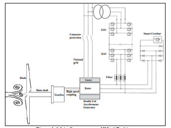 Figure 1: Main Components of Wind Turbine.
We introduced sum of different sinusoidal signals: varied amplitudes and frequencies in order to create wind speed model in Matlab Simulink as showed in the figure 2, which reflects approximately a recorded wind speed in Moroccan wind farms [10].
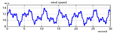 Figure 2: Wind Speed Model (m/s).
We assume that frictions are neglected and with the use of equations presented in previous paper [11], the wind turbine Matlab Simulink model is created.
Also, the DFIG modeling is based on equations of the stator and the rotor voltages (Us, Ur) in Park reference (d, q) as presented below:
 In park reference, the flux equations can be expressed as follows:

Where p represents pole pairs number of the DFIG.
We chose to control DFIG by stator flux. We seek to cancel the indirect stator flux in order to keep that direct stator flux. In this mode of DFIG operating conditions, control of the torque and flux is decoupled. This method is applied to improve the DFIG active and reactive power control performance, which allows controlling flux and torque dynamically and separately.
Based on equations (3) and (4) we have:
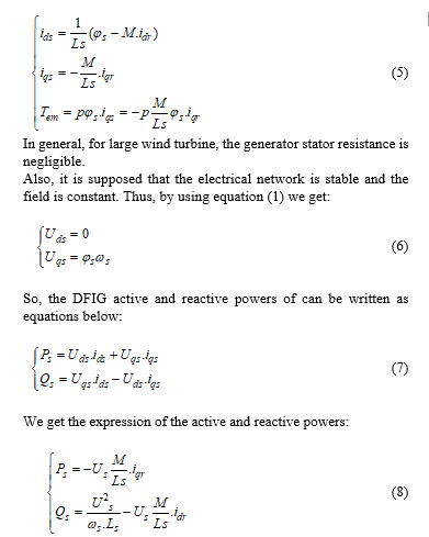
So, the equation (8) shows that the control of the active power is independent of the reactive power. Indeed, the active power is controlled by iqr the quadrature rotor current whereas the reactive power can be controlled by idr the direct rotor current.
 Also, to perform the machine control power there are two approaches for the field oriented control direct and indirect:
- Direct field oriented control is simple to implement : it consist on ignoring the terms of coupling in equation (9) and to establish an independent regulator in each axis to control the active and reactive power independently. But the direct field oriented control is not the most efficient [12];
- Indirect field oriented control: in this control we consider the coupling terms in equation (9) and we look for compensating them to control the powers and rotor currents. The indirect field oriented control is being more frequently used as it guaranties the easy operation over all the speeds range [13].
Table 1: Symbols and Abbreviations for generator Modeling
| Symbol | Quantity |
| (d, q)
(d, q) |
Stator flux components in Park reference
Rotor flux components in Park reference |
| Rs
Rr |
Stator resistance
Rotor resistance |
| Ls
Lr |
Stator cyclic inductances
Rotor cyclic inductances |
| ls | Stator leakage inductances |
| lr
Ms, Mr |
Rotor Leakage inductances
Mutual inductances between stator and rotor phases respectively |
| M
(d,q) (d,q) Tem (d,q) (d,q) |
Maximum mutual inductance between stator and rotor stage (the axes of the two phases coincide)
DFIG stator current components in Park reference DFIG rotor current components in Park reference
Electromagnetic torque
Stator voltage components in Park reference
Rotor voltage components in Park reference
DFIG active power
DFIG reactive power |
For DFIG modeling, we chose in this study to orient the stator flux of generator according to the direct axe. Moreover, we use the indirect vector field oriented control (IFOC) to increase the system performance. The wind energy conversion chain model created in Matlab Simulink is illustrated in figure 3 below.
The figure 3 presents the model of wind turbine created in Matlab Simulink which is composed of:
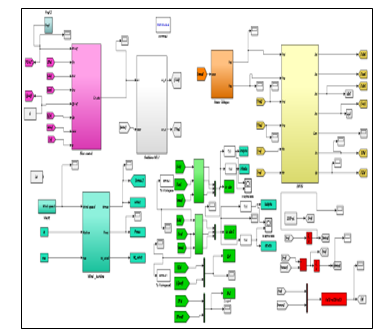 Figure 3: Wind Turbine Model in Matlab Simulink.
- The blue bloc at the bottom in the left contains modeling equations of wind turbine. In order to have maximum Cp we take = 0. Also, the wind speed model introduced as illustrated in figure 2;
- The yellow bloc at the top on the left includes the DFIG stator and rotor flux and currents equations. This bloc is linked to the power supply (orange bloc);
- The chosen control of generator is implemented in the pink bloc at the top on the right. Actually, the DFIG indirect field oriented control allows us to control dynamically and separately flux and torque. The bloc is connected to the grey bloc of Pulse Width Modulation PWM;
- We use the Concordia transformation in order to obtain DFIG currents Lissajous curves as figured in green blocs;
- We use mathematic equations in red blocs in order to get the DFIG slip g.
2.2. Simulations and Results
The graphs below represent the simulation at the first thirty seconds of the wind turbine model created in Matlab Simulink. We suppose that frictions are neglected.
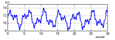 Figure 4: Wind Speed (m/s).
 Figure 5: Power Captured by Blade (w).
 Figure 6: Specific Speed λ.
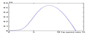 Figure 7: Cp Coefficient of Performance at =0.
In fact, figure 4 represents the variable wind speed which we apply to wind system conversion. The figures 5 and 6 show the system performance. Actually, the power captured by blade follows the same pace of wind speed.
The figure 7 shows coefficient of performance as a function of specific speed λ and the angle of orientation of the blade β. The coefficient reaches its maximum value which is 0.56 when β is zero and λ is optimal. Using the indirect vector field-oriented control (IFOC), we got the following figures representing asynchronous generator performance.
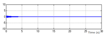 Figure 8: DFIG Indirect Stator Field φqs (wb).
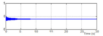 Figure 9: DFIG Direct Stator Field φds wb.
 Figure 10: Comparison between Ps and Psref.
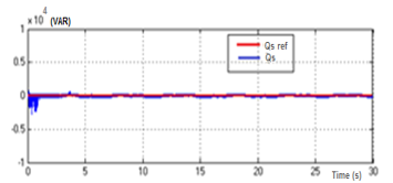 Figure 11: Comparison between Qs and Qsref.
In figures 8 and 9 the indirect field values of stator machine reached to zero and the direct stator field is constant since the stator flux of DFIG is chosen to be oriented following the direct axe. Furthermore, we choose Psref a reference for active power as a three steps form applied in different time. As illustrated in figure 10, the real active power pursues Psref. In addition, as showed in figure 11, the system reactive power follows Qsref which around zero value.
A zoom is presented in figure 12 of doubly-fed asynchronous generator three-phase stator currents.
 Figure 12: DFIG Three Phase Stator Currents.
It is shown that DFIG three-phase stator currents isabc have exactly sinusoidal shapes.
3. DFIG Diagnosis Defects Method
Nowadays, the electricity generated from wind turbines keeps increasing. However, faults in electrical power networks are inevitable events. According to data collected from yearly defects study of wind turbines Moroccan park [14], wind turbine connected to grid is exposed to various grid faults: 22% of defects are due to grid faults as presented in figure 13 (a). Also, grid defects can cause significant losses to wind system even if grid defects frequency remains less than other defects frequencies figure 13 (b) .
 Figure 13: Wind Turbines Defects: (a) type and (b) frequency.
The figure 13 shows defects type and frequency according to yearly Moroccan park data defects inspection.
Indeed, as indicated in sector graph figure 13.a wind turbines suffer from various internal electrical faults (48%), we mentioned for example over-current in DFIG stator phases, overvoltage in crowbar, overcurrent phase in GSC, thermal tripping in yaw drive motor because of cable isolation failure, etc . Also, linked to the electrical network, wind turbines are exposed to several grid faults (22%) such as lack of grid voltage, variation in the voltage magnitude and time duration and overheated generator due to the short circuit in the power supply, etc. The third defects type which represents 17% of total defects types is mechanical defects that occurs mainly in gearbox, electrical generator bearings, yaw motor, and also blades bearings. The rest defects types are essentially due to strong wind and other types.
The histogram above in figure 13.b shows different defects frequencies. It proves that the electrical defects are the most recurrent: they occur more than 194 times during a year in this park. In the second place come the mechanical defects with 152 times, followed by strong wind (89 times), grid faults (83 times) and others less than 20 times.
Usually, when fault occurs in the grid wind turbine is disconnected to avoid loss structure; however, for large wind energy capacity disconnection from the grid could generate problems. For this reason, multitudes of techniques are used to monitor the wind energy conversion chain health continually [15, 16].
In this current paper we propose diagnosis method for wind turbine DFIG electrical defects. The method is based on association of Fast Fourier Transform introduced and Lissajous curves analysis.
Indeed, Fast Fourier Transform (FFT) allows a conversion of a signal from its original domain to a representation in the frequency domain. The FFT analysis is applied in this paper to generator stator currents in order to determine the harmonic components amplitude and to get the maximum amplitude spectrum of the wavelet coefficients. The resulting spectrum offers a source of defects information [17].
To FFT analysis we associate Lissajous curves analysis. Currently, in the field of Lissajous curves, recent developments are realized in different domains such as the rotating machinery field [18], and defects diagnosis [19]. The method to get Lissajous curves of stator and rotor currents was explained in detail in previous paper [20]. Thanks to the curves obtained we will have an idea about defects kind impacting generator in wind conversion energy chain. In fact, when the defects appear, the Lissajous curves will be deformed depending on defects kind.
In the next part diagnosis method will be applied firstly to a non-defected generator.
4. Diagnosis Method Applied in Case of DFIG Normal Condition Operating
In order to have a reliable reference data for behaviour of DFIG in healthy case, the diagnosis method is developed for generator during defects-free operation.
As showed in figure 14, the FFT diagram of the stator three-phase current is implemented in Matlab Simulink.
 Figure 14: Fast Fourier Transform Spectrum of Stator Currents.
The signal fundamental frequency is at 50 Hz and the Total Harmonic Distortion (THD) which measures harmonics content is equal to 0.58%. In addition, harmonics are detected at frequency equals to 150 Hz and at 250 Hz. These harmonics are due to the use of PWM Pulse Width Modulation in the system, they represent the third and fifth harmonics. Also, magnitude percentages are respectively 0.1% and 0.05%.
Also, Lissajous curves of DFIG stator and rotor three-phase currents are simulated in Matlab Simulink.
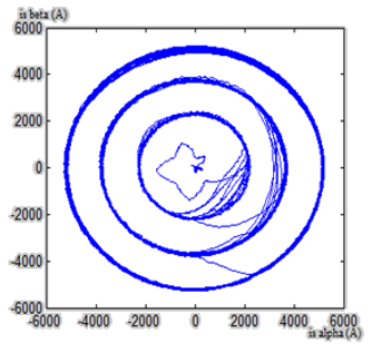 Figure 15: DFIG Stator Currents Lissajous Curves.
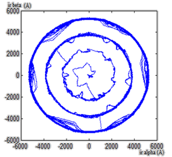 Figure 16: DFIG Rotor Currents Lissajous Curves.
The figures 15 and 16 illustrate DFIG stator and rotor currents Lissajous curves when generator is under normal operating condition. In this case, Lissajous curves have the form of three circles. These circles are the result of reference active power Psref which had been chosen as a signal of three steps presented in figure 10. Also, the rotor currents Lissajous curves have six petals flower shape (figure 16). This shape is explained by the fact that the rotor generator power supply is realized through the inverter with 6 switches.
In the next part we apply diagnosis method to defected DFIG.
5. Diagnosis Method Applied in Case of Open Stator Feeding Phases
As mentioned previously, larger wind turbines were developed and installed in windy world parts. Currently, the wind power generated is comparable to conventional fossil-fuel energy.
So, the impact of grid faults on wind power plants is considerable and could lead to blackouts if we allowed disconnection of wind turbines from grid. To keep wind turbines connected to the grid despite the presence of faults, we need to monitor and diagnose continuously the structure. Indeed, wind turbine generator is subjects to grid faults [21, 22]. We mentioned lack or variation of the voltage grid magnitude and frequency, and short circuit. Some recurrent grid faults are diagnosed by using the proposed diagnosis method [23].
Considering diversity of grid defects, we deal in this part with the problem of open stator feeding phases. This defect occurs rarely. However, when it occurs, it mainly affects generator and can cause significant losses.
In fact, when the stator is fed from two phases, the generator will continue to operate but the phase imbalance will cause its heating which can lead to eventual damage to DFIG, thereafter the loss of the whole structure.
5.1. Open stator supplying phase ‘a’
The figure 17 represents FFT of stator currents in case of generator fed from two phase power supply (phases ‘b’ and ‘c’).
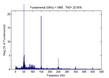 Figure 17: Stator Currents FFT Spectrum in Case of Open Stator Supplying Phase ‘a’.
In addition to harmonics at frequency equals to 150 Hz and at 250 Hz (case of defects-free generator), peaks appear in new frequency (at 25 Hz and 75 Hz). Also, Total Harmonic Distortion THD passed from 0.58% to 22.65% in case of defected generator. Indeed, higher THD means increase of generator heating and peak currents. As showed in figure 9 fundamental magnitude was 0.32%. But, when one feeding stator phase ‘a’ was opened, this fundamental magnitude value increases and passed to 24%.
The following figures show Lissajous curves respectively generator stator and rotor currents in case of open stator supplying phase ‘a’.
Comparing stator and rotor Lissajous curves obtained in cases of defects- free and defected generator, we see clearly in figures 19 and 20 that stator and rotor curves are deformed and the currents values increase.
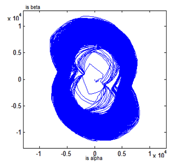 Figure 18: DFIG Stator Currents Lissajous Curves in Case of Open Stator Supplying Phase ‘a’.
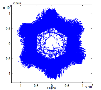 Figure 19: DFIG Rotor Currents Lissajous Curves in Case of Open Stator Supplying Phase ‘a’.
In fact, the opening of one stator feeding phase (phase ‘a’) generates an increase of the currents in the other phases. Also, the stator currents beta reach higher values than alpha currents. The curves have now elliptical shapes according to the vertical axis (stator currents beta). Also, curves circumference and thickness increased, which makes difficult observation of three separate curves.
The same for rotor currents Lissajous curves showed in figure 19 they are superimposed on each other because of increasing curves thickness. Which makes impossible detection of the three separate curves as Lissajous curves obtained in case of normal condition operating. Also, curves have six petals flower shape but they are deformed comparing to the reference curves.
 Figure 20: Stator Currents FFT Spectrum in Case of Open Stator Supplying Phase ‘b’.
5.2. Open stator supplying phase ‘b’
As illustrated in figure 20, the Fast Fourier Transform spectrum of DFIG stator currents when supplying phase ‘b’ is opened has approximately the same magnitude of fundamental in case of opened phase ‘a’. Also, harmonics at frequency 150 Hz, 250 Hz and 350 Hz appear in the FFT spectrum.
In term of Total Harmonic Distortion THD in this case, the value is 18.22%, a little less comparing to open supplying phase ‘a’.
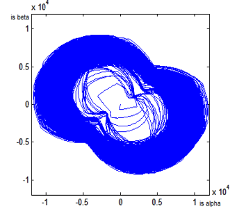 Figure 21: DFIG Stator Currents Lissajous Curves in Case of Open Stator Supplying Phase ‘b’.
In case of open stator feeding phase ‘b’, stator and rotor Lissajous curves obtained respectively in figures 21 and 22, are deformed comparing to the case of opening phase ‘a’.
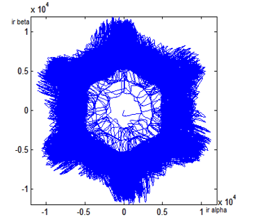 Figure 22: DFIG Rotor Currents Lissajous Curves in Case of Open Stator Supplying Phase ‘b’.
Indeed, the stator currents curves have elliptical shapes. But, for open phase ‘b’ stator currents alpha reach higher values than stator currents beta. Also, we note an inclination angle of 2π/3 of Lissajous curves compared to open phase ‘a’.
For rotor currents Lissajous curves showed in figure 22, we note that the curves have the same shape as figure 19 case of open phase ‘a’ with a slight increase in rotor currents.
 Figure 23: FFT Spectrum of Stator Currents Case of Open Stator Supplying Phase ‘c’.
5.3. Open stator supplying phase ‘c’
As showed in figure 23, the FFT spectrum of stator currents in the case of open supplying phase ‘c’ has approximately the same magnitude of fundamental in case of open phase ‘a’ or phase ‘b’. In addition, the THD in the case of open supplying phase ‘c’ is 17.89 %, it has approximately the same value comparing to open supplying phase ‘b’.
 Figure 24: DFIG Stator Currents Lissajous Curves in Case of Open Stator Supplying Phase c.
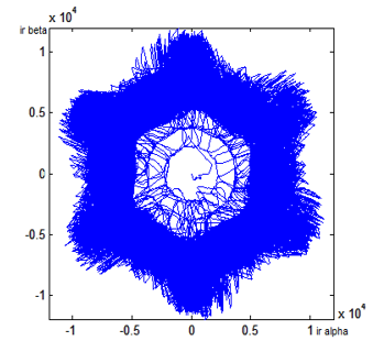 Figure 25: DFIG Rotor Currents Lissajous Curves in Case of Open Stator Supplying Phase ‘c’.
The figures 24 and 25 represent in that order stator and rotor Lissajous curves. Curves are deformed comparing to reference Lissajous curves the case of defects-free operation. Also, the stator beta currents reach higher values than alpha currents as curves when phase ‘a’ is opened, but in this case the stator beta currents have higher values.
As showed in figure 25, rotor currents Lissajous curves have kept the same shape as case of open phase ‘a’ and phase ‘b’.
We summarize that, the opening of one feeding DFIG stator phase generates an increase of the currents in the other phases and overheating of generator. Indeed, the resulting FFT spectrums analysing of stator currents help determine the amplitude of the harmonic components. These peaks amplitude, give us an idea about the defects severity affecting the wind energy chain.
Furthermore, the stator and rotor Lissajous curves are deformed according to defected generator supplying phase. So, we can detect DFIG defect types and know exactly which feeding phase is faulty.
6. Diagnosis Method Applied in Case of Defected Rotor Side Converter
Situated between the wind turbine generator and distribution networks, the back-to-back power converter has to satisfy both the generator side and grid side requirements [24]. As mentioned in paragraph 2.1, the control performed is indirect stator field oriented control. This way, DFIG is controlled by the rotor side converter. Owing to high voltage and a large transient current in the rotor windings, the power converter switching devices may be damaged due to their low power ratings of the switching devices [25]. So, connected to rotor circuit, a defected converter can cause generator damages. Hence, to diagnose DFIG rotor defects we apply a DFIG diagnosis method in case of open rotor side converter legs.
The figure below presents rotor side converter RSC components.
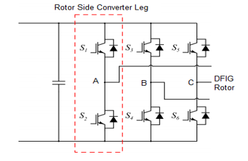 Figure 26: Rotor Side Converter with 3 Legs.
In the following part, we applied diagnosis method to DFIG in case of one rotor side converter leg opening.
The figures hereafter present the simulations results obtained in Matlab Simulink when RSC legs respectively (S1, S2), (S3, S4) and (S5, S6) are opened.
6.1. Open rotor feeding phase ‘a’
The figure above exposes the FFT spectrum of stator currents in the case of opened RSC leg (S1, S2). The fundamental magnitude value reaches 4782, and THD is 89.45%. Comparing these values to reference frequency spectrum in the case of DFIG defects free operation, we note that the fundamental magnitude exceeded the reference fundamental magnitude. Also, we observe an absence of harmonics at 150 Hz and 250 Hz due to defected RSC.
In term of total harmonic distortion, his value passed from 0.58% to 89.45% in case of one open feeding rotor phase. This high THD level of harmonics in stator currents waveforms cause increasing of DFIG temperature which reduce generator life and subsequently lead to the loss of generator.
The following figures show Lissajous curves respectively generator stator and rotor currents in case of open rotor feeding phase ‘a’.
 Figure 27: Stator Currents FFT Spectrum in Case of Open RSC Leg (S1, S2).
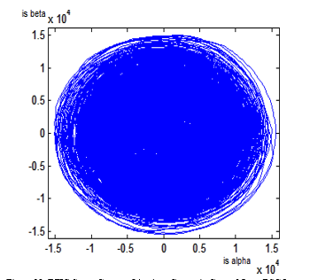 Figure 28: DFIG Stator Currents Lissajous Curves in Case of Open RSC Leg
Comparing stator Lissajous curves obtained in cases of defects- free and defected generator, we see clearly in figure 28 that stator Lissajous currents curves have kept the circular shape whereas circumference and thickness increased because of stator currents increasing which makes harder the differentiation of three separate curves.
Lissajous rotor curves, as presented in figure 28, are totally deformed and the rotor currents increase. In fact, the opening of one rotor feeding phase (phase ‘a’) generated by opening of one rotor side converter (S1, S2) increase the currents in the other phases and cause the curves superimposition on each other. Which make impossible detection of the three separate curves as Lissajous curves obtained in case of generator under normal condition operating.
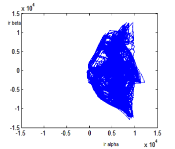 Figure 29: DFIG Rotor Currents Lissajous Curves in Case of Open RSC Leg
Also, the curves have now two deformed petals flower shape instead of six petals obtained in reference data. The rotor currents ir alpha in this case are located on the positive part of Lissajous curves.
In the next part, we apply diagnosis method to DFIG in case of open RSC leg (S3, S4).
 Figure 30: Stator Currents FFT Spectrum in Case of Open RSC Leg (S3, S4).
6.2. Open rotor feeding phase ‘b’
The figure 30 presents the FFT spectrum of stator currents in the case of open rotor feeding phase ‘b’. The fundamental magnitude reaches 4896 which is more than case of opened leg (S1, S2). The THD remains high with 87%. As the first case in paragraph 6.1 the harmonics at 150 Hz and 250 Hz did not appear in this frequency spectrum.
 Figure 31: DFIG Stator Currents Lissajous Curves in Case of Open RSC Leg
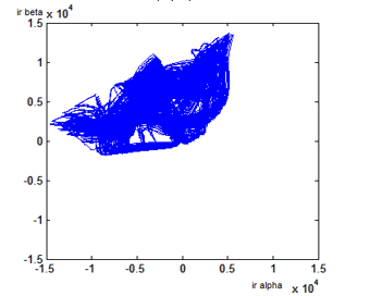 Figure 32: DFIG Rotor Currents Lissajous Curves in Case of Open RSC Leg
 Figure 33: Stator Currents FFT Spectrum in Case of Open RSC Leg (S5, S6).
When rotor feeding phase ‘b’ is opened the stator Lissajous curves obtained in figure 31 have kept the circular shape. They are similar to the first defected rotor case.
For rotor currents, the opening RSC leg (S3, S4) as presented in figure 32, generates Lissajous curves with shape of two petals flower. But these two petals are inclined by 2π/3 compared to the case of opening rotor phase ‘a’. For the last part of this paper, our proposed DFIG diagnosis method is applied in case of open RSC leg (S5, S6).
6.3. Open rotor feeding phase ‘c’
In the case of open rotor feeding phase ‘c’, we obtain the FFT spectrum of stator currents showed in figure 33. The fundamental magnitude reaches 4332 which is less than case of opened legs (S1, S2) and (S3, S4).
The THD reaches a maximum percentage with approximately 98% comparing to the previous opened phases.
According to the FFT spectrum graph and as foregoing cases, we note that the harmonics at 150 Hz and 250 Hz did not figure out.
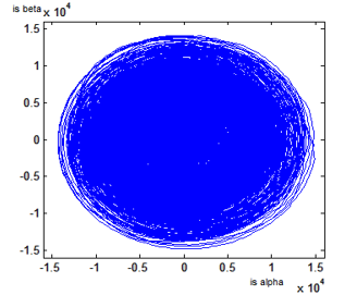 Figure 34: DFIG Stator Currents Lissajous Curves in Case of Open RSC Leg
 Figure 35: DFIG Rotor Currents Lissajous Curves in Case of Open IGBT Leg (S5, S6).
As opened feeding rotor phases ‘a’ and ‘b’, the stator Lissajous curves showed in figure 34 have similar shape. The generating Lissajous curves in figure 35 form two petals flower which are inclined by 4π/3 compared to the antecedent cases.
We deduct that, when one feeding DFIG rotor phase is opened the generator currents in the other phases increased. These high currents cause overheating of generator and can lead to the loss of generator. Through the frequency spectrums analysis of stator currents we determine the peaks amplitude, which show us the severity of the DFIG defects. And thanks to the stator and rotor Lissajous curves we detect exactly which feeding phase is faulty by means of deformation curves.
7. Conclusion
In this research paper, the method to diagnose wind turbine DFIG defects is developed through studying and analysing frequency spectrum and Lissajous curves of generator stator and rotor currents.
We start with creating wind energy conversion chain model in Matlab Simulink. Then, we apply indirect field oriented control to have separate and dynamical control on system flux and torque. Besides, the IFOC granted to have optimal, easy and efficient generator system operation over all the speed levels. Afterwards, based on studying generator currents frequency spectrum analysis and Lissajous curves, the method was developed with the aim of diagnosing and anticipating the potential DFIG wind turbine defects.
In the first step, this method was applied to generator under normal operating condition to get reliable reference data of generator behaviour.
In the second step, the technique was performed in case of open stator and rotor feeding phases. The results were compared with reference data obtained in case of defect-free operation.
Actually, according to defects types and by using Fast Fourier transform analysis, peaks appear or disappear at defined frequencies. Also, the maximum amplitude spectrum of the wavelet coefficients increasing, gives us an idea about the defects severity. Moreover, stator and rotor currents Lissajous curves are deformed considering shapes: thickness, circumference and direction of Lissajous curves in case of normal condition operating generator. We deduct that Lissajous curves are deformed according to the kind of defects attacking generator in wind turbine. Hence, the proposed DFIG diagnosis method allows recognition and prevention of potential defects attacking wind turbine.
Using Matlab Simulink, all the simulations had been realized. These results confirmed the efficiency and effectiveness of the proposed DFIG diagnosis defects method in the wind energy field.
- Global Wind Energy Council GWEC, “Global Wind Energy Report” April 2019.
- Moroccan Investment Development Agency, Kingdom of Morocco.
- R. M. R. Muthu, “Doubly Fed Induction Generator for Wind Energy Conversion System – a Survey”, International Conference on Energy Efficient Technologies for Sustainability, pp. 617-628, 2013.
- M. A. El-Sharkawi, “Wind Energy an Introduction”, University of Washington, Seattle, USA: 219, 2016.
- Outhred, Hugh & R. Bull, Stanley, “Meeting the Challenges of Integrating Renewable Energy into Competitive Electricity Industries”, 2007.
- T.R. Ayodele, A.A. Jimoh, J.L Munda and J.T Agee, “Challenges of Grid Integration of Wind Power on Power System Grid Integrity: A Review”, International Journal of Renewable Energy Research”, Vol.2, No.4, 2012.
- K. Loudiyi, et al., “Grid Code Status for Wind Farms Interconnection in Northern Africa and Spain: Descriptions and Recommendations for Northern Africa”, Renewable and Sustainable Energy Reviews, Elsevier, vol. 81, part 2, pp. 2584-2598, 2018.
- Hansen, et al., “Grid Fault and Design-Basis for Wind Turbines – Final Report”, Roskilde, Risø National laboratoriet for Bæredygtig Energi, Denmark, Forsknings center Risoe. Risoe-R, no. 1714, 2010.
- M. Abomahdi and M.Srivastava, “Control of Grid Voltage and Power of Doubly Fed Induction Generator wind turbines during grid faults”, IOSR Journal of Electrical and Electronics Engineering (IOSR-JEEE), vol. 9, iss. 4, pp 12-21, 2014.
- F. El Hammouchi, L. El Menzhi and A. Saad, “Wind Turbine Doubly-Fed Asynchronous Machine Diagnosis Defects-State of the Art”, DEStech Transactions on Environment Energy and Earth Sciences, pp. 300-306, October 2017.
- F. El Hammouchi, L. El Menzhi, A. Saad, Y. Ihedrane and B. Bossoufi, “Wind Turbine Doubly-Fed Asynchronous Machine Diagnosis Defects -Part two”, 2018 IEEE 5th International Congress on Information Science and Technology (CiSt), Marrakech, pp. 449-454, 2018. DOI: 10.1109/CIST.2018.8596498
- M. Allam, B. Dehiba, M. Abid , Y. Djeriri and R. Adjoudj, “Etude Comparative entre la Commande Vectorielle Directe et Indirecte de la Machine Asynchrone à Double Alimentation (MADA) Dédiée à une Application Eolienne”, Journal of Advanced Research in Science and Technology (JARST),vol. 1, no. 2, pp. 88-100, 2014.
- Y. Ihedrane, C. El Bekkali, and B. Bossoufi, “Power Control of DFIG-Generators for Wind Turbines Variable-Speed”, International Journal of Power Electronics and Drive System, vol. 8, no. 1, pp. 444-453, 2017.
- F. El Hammouchi, L. El Menzhi and A. Saad, “Wind Turbine Double-Fed Asynchronous Machine Diagnosis Defects-Part One”, International Congress of Industrial Engineering and Systems Management CIGIMS, Meknes, Morocco, pp. 380-383, Mai 2017.
- A. Joshuva and V. Sugumaran, “Fault Diagnostic Methods For Wind Turbine: A Review”, ARPN Journal of Engineering and Applied Sciences, vol. 11, no. 7, pp. 4654-4668, 2016.
- L. M. Popa, B. B. Jensen, E. Ritchie and I. Boldea, “Condition monitoring of wind generators”, 38th IAS Annual Meeting on Conference Record of the Industry Applications Conference, 2003., Salt Lake City, UT, USA, vol. 3, pp. 1839-1846, 2003. Doi: 10.1109/IAS.2003.1257819
- E. ElBouchikhia, V. Choqueuse and M. Benbouzid,“Induction Machine Faults Detection Using Stator Current Parametric Spectral Estimation”, Mechanical Systems and Signal Processing, vol. 52–53, pp. 447-464 , 2015.
- H. A. H. Al-Khazali and M. R. Askari, “Geometrical and Graphical Representations Analysis of Lissajous Figures in Rotor Dynamic System”, Journal of Engineering (IOSR), vol. 2, issue. 5, pp. 971-978, 2012.
- L. El Menzhi, and A. Saad, “Lissajous Curve of an Auxiliary Winding Voltage Park Components for Doubly-Fed Induction Machine Electrical Faults Diagnosis”, The Journal of Advanced Materials Research, vol. 860-863, pp. 2223-2231, 2014.
- F. El Hammouchi, L. El Menzhi, A. Saad, Y. Ihedrane, and B. Bossoufi, “Wind Turbine Doubly-Fed Asynchronous Machine Diagnosis Defects Using Stator and Rotor Currents Lissajous Curves”, IJPEDS International Journal of Power Electronics and Drive System, Vol. 10, No. 2, pp. 961-970, 2019.
- A. Gupta , Dr. A. Shandilya, “Challenges of Integration of Wind Power on Power System Grid : a Review”, International Journal of Emerging Technology and Advanced Engineering ,vol. 4, iss. 4, April 2014.
- A. Mouahid, A. Khamlich, A. Saad, “Study Of The Behaviour Of Wind Turbines Using Doubly Feed Asynchronous Generator During Voltage Dip”, Mediterranean Telecommunication Journal, vol. 5, no. 2, pp. 126-132, june 2015.
- F. El Hammouchi, L. El Menzhi and A. Saad, “Diagnosis Method for Wind Turbine Doubly Fed Induction Generator under Grid Defects”, International Journal of Information Science & Technology – IJIST, vol. 3, no. 3, pp. 46-55, 2019.
- F. Blaabjerg, M. Liserre, and K. Ma, “ Power Electronics Converters for Wind Turbine Systems”, IEEE Transactions on Industry Applications, vol. 48, no. 2, pp. 708-719, 2012
- J. J. Justo and F. A. Mwasilu, “Low Voltage Ride through Enhancement for Wind Turbines Equipped with DFIG under Symmetrical Grid Faults”, Tanzania Journal of Engineering and Technology, vol. 37, no. 2, pp. 125-136, December 2018.