Mechanical Testing Methods for Body-Powered Upper-Limb Prostheses: A Case Study

Adv. Sci. Technol. Eng. Syst. J. 4(5), 61–68 (2019);
 DOI: 10.25046/aj040508
3D-printing technologies have greatly influenced the field of fabrication of medical devices. In particular, Fused Deposition Modeling 3D printing has emerged as one the most popular and most promising technologies for fabricating upper-limb prostheses. Over the last years, a variety of types and designs of 3D-printed hand prostheses have been created and are commercially available. However, there are no standards or established procedures for testing these devices. Available information regarding their long-term performance and functionality is very limited. This paper presents a case study of mechanical testing methods applied to a specific design of an upper-limb prosthesis. The device and its subassemblies were subjected to flexion test in hyperextension and abduction conditions, fatigue/wear test, and tensile test. The experimental results are presented and examined. Testing procedures, adaptations and recommendations are described and discussed to demonstrate ways of generating reliable data that serve for comparison among different hand prostheses designs.
1. Introduction
The fabrication of medical devices is one of the most influenced fields by 3D printing technologies advances. Particularly, in the last years, 3D printed hand prostheses have emerged as a promising low-cost alternative, compared to conventional hand prostheses, to fulfill the need for these devices in developing countries [1]. Currently, Fused Deposition Modeling (FDM) is one of the most common and inexpensive technologies for fabricating functional end-use parts by 3D printing, including hand prostheses. However, FDM has a disadvantage related to the anisotropy generated by the process and its corresponding effect on mechanical properties. A material fabricated by 3D printing shows a ductile behavior in the orientation of the bead deposition, but a brittle one in the perpendicular orientation. Therefore, FDM printed components are susceptible to fracture in the building orientation; a failure mechanism called delamination. While the effect on mechanical properties of many fabrication parameters such as layer height, infill pattern, density, nozzle diameter, build plate temperature, printing orientation and velocity [2, 3, 4, 5, 6, 7] has been evaluated using 3D-printed test specimens, little advances have been made in testing and characterizing entire components fabricated using FDM 3D-printing.
Although the popularity and the use of 3D printed hands keep increasing, there is a lack of standards for fabrication and testing of these devices and very limited information available in terms of their long-term performance and functionality. Existing hand prostheses standards and testing procedures are not directly applicable, even for currently commercial multi-fingered and dexterous hand prostheses, because they were conceived mainly for conventional hook prostheses. Moreover, hand prostheses manufacturers use their design-specific tests to provide full specifications of their commercial products.
In this context, different researchers have explored the possibility of adapting existing methods and implementing variations, according to their investigation’s objectives and available resources, to evaluate the performance of open-source and specific models of 3D printed upper-limb prostheses. Tests have been conducted to evaluate mechanical properties such as tensile strength, impact resistance, flexural strength, and fatigue resistance, both in the whole prostheses and sub-assemblies, with
parameters (test velocity, applied load, number of cycles, etc.) that resemble conditions of activities of daily life (ADL). A review of these tests has been presented by the authors in the conference BIBE 2018 [8] and is summarized as follows.
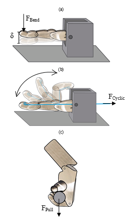 Figure 1. Schematic drawings of the different mechanical tests found in the literature. (a) Finger flexion test, (b) endurance/fatigue test and (c) hand tensile test. Adapted from [8].
Tenim [9] and Koprnicky [10] analyzed the mechanical behavior of phalanges of prosthetic hands employing hyperextension (see Figure 1a) and lateral bending test and cyclic flexion-extension test (see Figure 1b). The bending tests were intended to evaluate the maximum load that a phalange can withstand and extrapolate the results to compute the maximum load that can be carried by all of the fingers of a prosthetic hand. These bending tests have been also applied to individual fingers from robotic grippers [11]. Furthermore, the purpose of the cyclic flexion-extension test was to measure the endurance of a finger under the application of several fatigue cycles and to determine the mode of failure under this condition (e.g. damage of one of the finger components or wear of the flexion cables channels). In addition, Crisco and Wolfe [12] analyzed the finger biomechanics and proposed testing procedures to mimic the conditions to which a prosthesis is subjected to when conducting activities of daily living. While the ASTM F1781 standard [13] provides some guidance for finger fatigue test, Joyce and Unsworth [14] have proposed a set of parameters to be applied, such as the flexion-extension load magnitude: 10-15 N, pinch load: 100 N, the angular amplitude of the motion: 0-90 degrees, and the frequency: 1.5 Hz.
Among the tests to which prosthetic hand subassemblies could be subjected to, the ISO 22523 standard [15], annex A, proposes the distal tensile test (see Figure 1c). In this test, a hand subassembly is induced to perform a power grip on a 19 mm diameter cylindrical object. As schematically observed in Figure 1c, the object is pulled away, forcing the fingers to extend or to break. In this way, it is possible to establish the maximum load that the prosthesis can withstand without failure. Additional tests involving grasping movements with a cylindrical object have been proposed in [16, 17, 18]. Cylindrical grip test is of key importance because it mimics the movement conditions of most of the body-powered hand prostheses, i.e. opening and closing of all of the fingers at the same time. Furthermore, the ISO 22523 standard describes the procedures to conduct hand or wrist flexion tests in the case of transradial prostheses.
This paper presents a case study of mechanical testing methods applied to an upper-limb prosthesis. The study is focused on the 3D-printed D1M Hand (acronym in English for Dando Una Mano, Giving a Hand) [19] (see Figure 2). The D1M hand was designed for transmetacarpal or partial hand amputations and was fabricated by the FDM 3D printing process. Due to its design and functionality the D1M hand was subjected to finger flexion test (in the hyperextension and abduction/adduction directions) to measure individual finger maximum load, finger cyclic flexion-extension to measure individual finger durability, and hand tensile test to measure the maximum possible load that the hand can withstand while performing a cylindrical grasp. Schematic drawings and a description (references, conditions, outcomes, and objectives) of these tests are shown in Figure 1 and Table 1 respectively.
This work complements the one presented by the authors in BIBE 2018 [8]. This manuscript includes a summary of the design and fabrication process of the D1M hand, the experimental details and testing procedures description; with particular emphasis placed on the machine adaptations for positioning and supporting the tested hand and finger samples, and the discussion of obtained results.
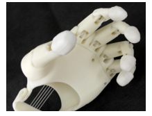 Figure 2: D1M hand prosthesis prototype. Image from [19].
2. Experimental Procedure
The mechanical tests were performed using universal testing machines. The D1M hand was fabricated using a commercially available desktop 3D printer. The use of commercially accessible equipment will allow the experimental procedures to be replicated and the results to be compared with those obtained by other researchers. The assemblies and accessories presented in this work can be modeled in CAD software and then minor modifications can be made to accommodate different designs. Validation of the printing parameters and methodology was performed with detailed testing applied to the D1M hand.
Table 1: Description of the mechanical resistance tests applied to the D1M Hand (adapted from [8]).
| Type of test | Test description | |||
| Based on (guide or standard) | Test conditions | Recorded outcomes | Objective | |
| Finger flexion | ISO 178, ASTM 790 and the works of Tenim [9] and Koprnicky et al. [10] | Velocity of the test: 1% the gage length per minute.
Finalize when: Maximum deflection is 5% or failure. Different tests: Hyper-extensive and lateral loading. |
Displacement and force against time. | Estimate the mechanical strength of the fingers to withstand forces that over-extend (hyper-extensive loading) or bend the fingers laterally (lateral loading). The target load value is 30 N according to [20] |
| Finger cyclic flexion-extension | ISO 14243-1 and the works of Tenim [9] and Joyce et al. [14]. | Cyclic loading frequency: 1.5-2 Hz.
Finalize when: achieve 1,200,000 cycles or failure of whichever component. Load at the MCP joint: 10 – 15 N. Pinch force: 100 N. Finger base joint range of motion: 0 – 90 degrees. |
Cycles can achieve the prosthesis until the failure. Wear of the components measured by weight difference before and after the test. | Calculate the number of cycles the prosthetic finger can withstand. The target value is 1,200,000 cycles (equivalent to 4 years of use) according to [21] |
| Hand tensile test | ISO 22523-2006, annex A.8.2 [15] | The prosthesis grasps a 100mm x diameter 19 mm cylinder.
An external force pulls the cylinder out of the hand. Preload: 10 N Load: increases at a rate of 1 – 10 N/s until failure. |
Displacement and force against time. | Estimate the maximum payload of the whole prosthesis when performing a cylindrical grasp. |
2.1. Fabrication of the D1M hand prosthesis
The D1M hand was fabricated by FDM 3D printing with an Ultimaker 3+ Extended machine; the material employed was acrylonitrile butadiene styrene (ABS). Table 2 shows the general 3D printing process fabrication parameters that were applied to all of the main components (fingers, palm and forearm).
The prosthesis was designed based on the anthropomorphically structure of the user and the functionality of the 4 linkages mechanism [19]. ABS is an optimal polymer for this use because of its strength and low density. As mentioned previously, the mechanical resistance of the 3D printed hand depends on the manufacturing orientation, caused by the intrinsic anisotropy of the manufacturing and its deposition of consecutive layers. For this reason, optimal printing orientation for each component was chosen based on factors such as maximizing the area of the critical cross-section under stress (to prevent delamination) and attaining the best surface quality with no support material for important geometrical features (like shaft supports). Table 3 and Figure 3 shows the orientation of each component of the hand and its printing parameters. In addition, it was observed that for the palm less infill density is placed than in the fingers, because in the continuous use of the prosthesis it was identified that the fingers were critical pieces, due to the small thickness in the lace. Many other existing hand prostheses designs also come with suggested infill percentages, which adds another variable influencing the resulting mechanical properties of the resulting device. With the purpose of finding the exact technical specifications of the prosthesis, mechanical tests were performed based on the experimental parameters found in the literature.
2.2. Experimental Procedure on D1M hand
Three different tests were conducted in the D1M hand: first the hand tensile test, chosen because the main actions performed by upper limb prostheses require a cylindrical grip; then, finger flexion tests were performed in order to know the maximum weight that an individual finger can resist; and finally, the finger fatigue / wear test to estimate the prosthesis’ durability and the wear due to its use. These tests required the design of custom fixation components to be placed between the hand components and the testing machine.
Table 2: 3D Printing parameters for the components of the D1M Hand.
| Parameter | Value |
| Nozzle Temperature | 230 °C |
| Build plate Temperature | 100 °C |
| Printing speed | 65 mm/s |
| Layer height (Z-axis resolution) | 0.2 mm |
| Wall thickness | 1.2 mm |
| Infill pattern | Linear |
Table 3: 3D Printing Parameters specific to each component.
| Piece | Layer thickness [mm] | Infill [%] | Angle orientation |
Figure |
| Finger | 0.1 | 50 | 17° and 25° | Figure 3a |
| Palm (front side) | 0.2 | 30 | 28° | Figure 3b |
| Palm (backside) | 0.2 | 30 | 15° | Figure 3c |
| Forearm | 0.2 | 50 | 32° | Figure 3d |
2.2.1. Hand tensile test
The tensile test was performed in the whole hand assembly to evaluate the maximum load that the prosthetic hand can withstand when it is performing a cylindrical grasp movement. The test was conducted using a Zwick Roell Z050 tensile test machine with the test parameters defined by ISO 22523:2006 [15]. Three whole hand assemblies were tested. As shown in Figure 4a, a flat area accessory to connect the machine jaws with the hand was fabricated, it also served to keep the assembly aligned with the axis on which the machine exerts force. This accessory was printed in ABS and 100% filling density was used. Additionally, a grasping device (see Figure 4b) was fabricated to allow the prosthesis to make a cylindrical grip. On the other hand, a support device was added to maintain the wrist flexion needed to close the fingers around the grasping device. To ensure that the test can reproduce a real-use condition, the prosthesis must be tested while activated with its fingers closed. For this reason, a pair of accessories were designed to keep the prosthesis locked as if it were activated by a user exerting force with the stump. A steel accessory (see Figure 4c) was manufactured to support the hand and withstand relatively high loads without deforming. In addition, an accessory acting as a support point of the inner part of the palm was printed (see Figure 4d). Figure 5 shows the complete assembly to perform the testing.
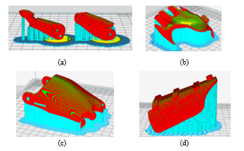 Figure 3. Orientation of the hand prosthesis’ main components: (a) finger phalanges, (b) front of palm, (c) back of palm and (d) forearm.
 Figure 4. Accessories for the optimal fix between the prosthesis and the testing machine.
The test is performed until the failure of any component (or until the prosthesis stops holding the grip due to the deformations that occur in the threads that cross the phalanges).
2.2.2. Finger Flexion test
Flexion tests were conducted in the fingers to evaluate their maximum load-carrying capacity. The tests were carried out simulating two conditions: a finger extended in a horizontal plane (hyperextension test), and a finger extended in a vertical plane (abduction test). The tests were performed using a Zwick Roell Z0.5 multi-test machine. Three samples of middle and little fingers (longest and shortest finger of a hand, respectively) were subjected to each condition of the test. The test speed was proportional to the length of the finger, which in turn depended on the test condition. For the hyperextension condition, the test speed was 6.6 mm/min and 4.6 mm/min for the middle and little finger, correspondingly. For the abduction condition, the speed was 7.3 mm/min and 5 mm/min for the middle and little finger respectively. Three accessories were needed for this test: the general coupling, the secondary coupling and the bending punch. Figure 8a shows the assembly designed in the CAD software. The general coupling (see Figure 6) was fixed on the machine table and housed the secondary coupling and the finger. The secondary coupling (see Figure 7) varied depending on the size of the finger and the type of test (hyperflexion or abduction). The bending punch was fabricated from a sheet of steel and had a U shape in order to avoid the slip with the 3D printed finger, as shown in Figure 8b.
 Figure 5. The complete assembly of the hand tensile test. Arrow indications correspond to the accessories shown in Figure 4.
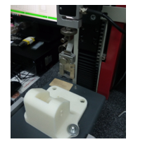 Figure 6. 3D printed coupling made of white ABS and punch that exerts the bending force.
2.2.3. Finger fatigue/wear test
The fatigue/wear test was performed to evaluate the capacity of the index finger assembly (3D printed phalanx, wire and pins) to perform a cyclic pincer grasp movement and measure the possible wear between the threads and the internal channels of the prosthesis, and the metal pins with the phalange holes. A Zwick Roell Z0.5 machine was used for the test, subjecting samples of the index finger to 24000 cycles in flexion mode. The test load variation was from 2 N to 80 N to ensure the force in the fingertip of 15N (as suggested in [21]), with a displacement speed of 1000 mm/min. The wire that pulls the mechanism to operate the finger was placed in the machine’s jaw (see Figure 9) and was connected with the finger through a bronze pulley (see Figure 10b) that also that also serves as an alignment tool. Then the finger was set up in a 3D printed holder to facilitate the test and a sensor (a Force Sensitive Resistance sensor with a magnitude range: 100 g – 10 kg) was positioned in the area of contact with the fingertip in order to evaluate the pincer grasp load (see Figure 10a).
Three samples were tested and, besides analyzing their capacity to withstand cyclic loads, the wear resistance of the assembly was evaluated by weighing the samples before and after the test.
 Figure 7. Accessories designed for the (a) middle finger hyperextension, (b) middle finger abduction, (c) little finger hyperextension and (d) little finger abduction tests.
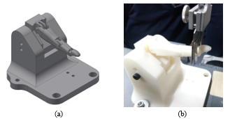 Figure 8. (a) CAD design and (b) fabricated components of the finger flexion test assembly.
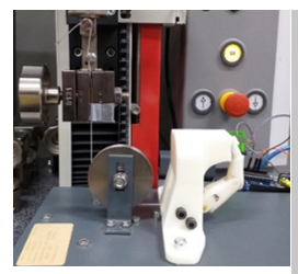 Figure 9. The complete assembly for the fatigue/wear test.
 Figure 10. Accessories for the finger fatigue/wear test: (a) sensor on its 3D printed holder and (b) pulley.
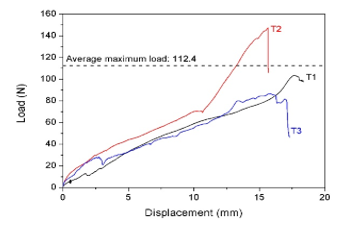 Figure 11: Tensile test curves for the D1M prosthetic hand samples
3. Results and Discussion
3.1.1. Hand tensile test
Figure 11 shows the load-displacement curves for the tensile test in the three assembled prosthetic hands (samples T1, T2 and T3). The average maximum tensile load that the hand can withstand before failure is 112.4 N. Discontinuities in the curves and differences in behavior for each sample could be attributed to factors inherent to the 3D printing process, and to re-accommodation events of the hand assembly through the test due to the elastic and plastic deformations experienced by the wire.
3.1.1. Finger Flexion test
Figure 12a and Figure 12b show the load-displacement curves for the middle and little finger samples obtained from the flexion tests in hyperextension condition (hyperflexion). The average maximum load for the middle and little finger in hyperflexion mode is 25 N and 27.2 N, correspondingly. The average maximum displacement is 50.6 mm for the middle finger and 51.3 mm for the little one. Although the average maximum load and the average maximum displacement values are similar for both fingers, the dispersion among the obtained values is bigger for the case of the middle finger. Figure 13a and Figure 13b present the load-displacement plots for the middle and little fingers obtained from the flexion tests in abduction condition. The average maximum load for the middle finger in hyperextension and abduction condition is 25.0 N and 29.6 N, correspondingly. For the little finger, the average maximum force is 27.2 N in hyperextension mode, and 47.9 N in abduction condition. The little finger can withstand bigger loads in both test conditions due to the fact that the length in cantilever mode is shorter, compared to that for the middle finger. The test curves exhibit discontinuities due to re-accommodation of the finger assembly. Table 4 presents the set of tested samples and the corresponding designation.
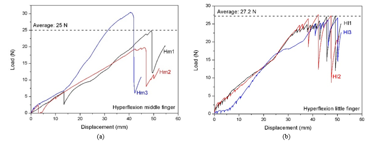 Figure 12. Finger hyperextension test curves for the middle (a) and little (b) fingers of the D1M hand. The horizontal dashed lines represent the average of the maximum load values.
 Figure 13. Finger abduction test curves for the middle (a) and little (b) fingers of the D1M hand. The horizontal dashed lines represent the average of the maximum load values.
As shown in Figure 14a, failure of the fingers in hyperextension occurs at the link of the proximal phalanx. On the other hand, failure in the abduction condition takes place at the MCP joints, as observed in Figure 14b; cracks nucleate in this area and propagate producing misalignment of the pins. This mechanism might be the reason why significant variations in the load-displacement curves beyond the linear region are evidenced (see Figure 15). Despite being thinner and thus having a smaller cross-sectional area for load distribution, the little finger can withstand a greater load than the middle finger due to the shorter moment arm from its base to the fingertip, which should be taken into consideration for the design.
In the case of the fatigue test, after 24000 cycles of loading, no component from the finger assembly (3D printed pieces, metallic pins, and wires) show any type of failure. Table 5 shows the weight of the fatigue/wear test samples before and after the test. A relatively small difference in weight was recorded as a result of the cyclic load and wear on the contacting parts, the average percentage of variation of weight was 0.05%. The 24000 cycles represent a period of 27 days of use of the prosthetic hand, considering that an average person performs 3680 grasp movements per day [22] and that a prosthetic hand user employs it 4 hours per day [23]. Based on the obtained results, the expected annual weight loss of the D1M hand would be 0.67%, which is a low value when compared to the wear rate for common materials. Figure 16 shows one of the fatigue test samples after the test; the encircled area highlights the ABS material particles resultant from the wear on the contacting parts.
Table 4: Designation of test specimens.
| Test type | Sample | Number of samples | Samples designation |
| Hyperflexion | Middle finger | 3 | Hm1, Hm2 and Hm3 |
| Hyperflexion | Little finger | 3 | Hl1, Hl2 and Hl3 |
| Abduction | Middle finger | 3 | Am1, Am2 and Am3 |
| Abduction | Little finger | 3 | Al1, Al2 and Al3 |
 Figure 14: D1M prosthetic hand finger failure location under hyperextension (a) and abduction (b) conditions.
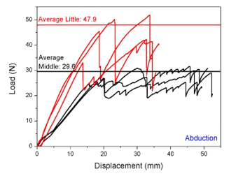 Figure 15: Finger abduction test curves for the middle (black) and little (red) fingers of the D1M hand. The horizontal lines represent the average of the maximum values per finger.
Table 5. Weight of fatigue/wear test samples before and after the test.
| Sample | Weight (g) | Weight loss (%) | |
| Before test | After test | ||
| 1 | 6.7117 | 6.7109 | 0.012 |
| 2 | 6.7090 | 6.7020 | 0.104 |
| 3 | 6.8066 | 6.8040 | 0.038 |
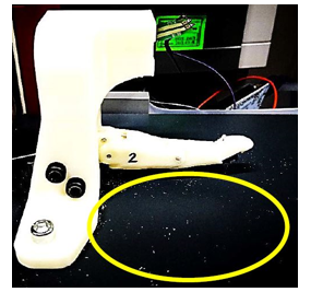 Figure 16: Fatigue test sample
4. Conclusions
In this work, mechanical testing methods for upper limb prostheses were adapted and applied to a specific design, the D1M hand. Details of the experimental procedure have been described and test results have been discussed. The maximum tensile load that the D1M prosthetic hand can withstand is 112.4 N. Furthermore, maximum flexion strength of fingers in hyperextension and abduction conditions is 27.2 N and 48 n, respectively. It was also determined that after 24000 cycles of flexion no component of the fingers assembly of the D1M prosthetic hand exhibits any type of failure.
Obtained mechanical resistance tests results can be utilized to compare future experimental and simulation results. Moreover, our findings and the case described contribute in generating data for the 3D-printed prostheses community since standardization is needed in order to evaluate properties and performance of existing and future designs, which will allow for objective comparison between them and the continuous improvement of their mechanical specifications.
- B. Phillips, G. Zingalis, S. Ritter and K. Mehta, “A review of current upper-limb prostheses for resource-constrained settings,” in IEEE Global Humanitarian Technology Conference (GHTC), Seattle, WA, USA, 2015.
- A. E. Tontowi, L. Ramdani, R. V. Erdizon and D. K. Baroroh, “Optimization of 3D-Printer Process Parameters for Improving Quality of Polylactic Acid Printed Part,” International Journal of Engineering and Technology (IJET), vol. 9, no. 2, pp. 589-600, 2017.
- J. Torres, M. Cole, A. Owji, Z. DeMastry and A. P. Gordon, “An Approach for mechanical property optimization of fused deposition modeling with polylactic acid via design of experiments,” Rapid Prototyping Journal, vol. 22, no. 2, pp. 387-404, 2016.
- B. Tymrak, M. Kreiger and J. Pearce, “Mechanical properties of components fabricated with open-source 3-D printers under realistic environmental conditions,” Materials and Design, vol. 58, pp. 242-246, 2014.
- M. Fernandez-Vicente, W. Calle, S. Ferrandiz and A. Conejero, “Effect of Infill Parameters on Tensile Mechanical Behavior in Desktop 3D Printing,” 3D Printing and Additive Manufacturing, vol. 3, no. 3, pp. 183-192, 2016.
- A. R. Torrado and D. A. Roberson, “Failure Analysis and Anisotropy Evaluation of 3D-Printed Tensile Test Specimens of Different Geometries and Print Raster Patterns,” Journal of Failure Analysis and Prevention, vol. 16, no. 1, pp. 154-164, 2016.
- J. Cantrell, S. Rohde, D. Damiani, R. Gurnani, L. DiSandro, J. Anton, A. Young, A. Jerez, D. Steinbach, C. Kroese and P. Ifju, “Experimental Characterization of the Mechanical Properties of 3D Printed ABS and Polycarbonate Parts,” Rapid Prototyping Journal, vol. 23, no. 4, pp. 89-105, 2017.
- R. Mio, M. Sánchez and Q. Valverde, “Mechanical Testing Methods for Body-Powered Upper-Limb Prostheses: A Review,” in IEEE 18th International Conference on Bioinformatics and Bioengineering (BIBE), Taichung, 2018.
- S. Tenim, Design of an Affordable Anthropomorphic Mechanical Prosthetic Hand, M. A. Thesis, University of Cape Town, South Africa, 2014.
- J. Koprnicky, J. Safka and M. Ackermann, “Using of 3D Printing Technology in Low Cost Prosthetics,” Materials Science Forum, vol. 919, pp. 199-206, 2018.
- Robotiq, “How we tested the Robotiq Adaptive Gripper,” [Online]. Available: https://blog.robotiq.com/bid/31435/How-we-Tested-the-Robotiq-Adaptive-Gripper. [Accessed 7 Junio 2018].
- J. J. Crisco and S. W. Wolfe, “Mechanical testing of orthopedic implants: Hand and wrist,” Mechanical Testing of Orthopaedic Implants, Vols. Duxford, United Kingdom, pp. 63-98, Woodhead Publishing, 2017.
- American Society for Testing and Materials, ASTM F1781 – 15, Elastomeric Flexible Hinge Finger Total Joint Implants, West Conshohocken: PA: ASTM International, 2015.
- T. J. Joyce and A. Unsworth, “A test procedure for artificial finger joints,” Proceedings of the Institution of Mechanical Engineers,Part H: Journal of Engineering in Medicine, vol. 216, no. 2, pp. 105-110, 2002.
- International Organization for Standardization, ISO 22523 External limb prostheses and external orthoses, Switzerland: Requirements and test methods, 2006.
- National Institute of Standards and Technology, “Performance Metrics and Benchmarks to Advance the State of Robotic Grasping,” [Online]. Available: https://www.nist.gov/programs-projects/performance-metricsmetricsand-. [Accessed 4 June 2018].
- J. T. Belter, M. T. Leddy, K. D. Gemmell Jr. and A. M. Dollar, “Comparative Clinical Evaluation of the Yale Multigrasp Hand,” in IEEE RAS/EMBS International Conference on Biomedical Robotics and Biomechatronics (BioRob), UTown, Singapore, 2016.
- R. U. N. &. Media, “A hand for the hand-makers,” 3 April 2016. [Online]. Available: http://news.rice.edu/2016/04/13/a-hand-for-the-hand-makers-3/. [Accessed April26 2018].
- M. Bustamante, R. Vega-Centeno, M. Sánchez and R. Mio, “A Parametric 3D-Printed Body-Powered Hand Prosthesis Based on the Four-Bar Linkage Mechanism,” in IEEE 18th International Conference on Bioinformatics and Bioengineering (BIBE), Taichung, 2018.
- G. Smit, D. H. Plettenburg and F. C. T. van der Helm, “The Lightweight Delft Cylinder Hand: First Multi-Articulating Hand That Meets the Basic User Requirements,” in 431-440, 23, 2015.
- J. T. Belter, J. L. Segil, A. M. Dollar and R. F. Weir, “Mechanical design and performance specifications of anthropomorphic prosthetic hands: A review,” Journal of Rehabilitation Research & Development, vol. 50, no. 5, pp. 599-618, 2013.
- V. Nagaraja, J. Bergmann, D. Sen and M. Thompson, “Examining the needs of affordable upper limb prosthetic users in India: A questionnaire-based survey,” Technology and Disability, vol. 1, pp. 1-10, 2016.
- M. Vergara, J. Sancho, V. Gracia and A. Pérez, “An introductory study of common grasps used by adults during performance of activities of daily living,” Journal of Hand Therapy, vol. 27, pp. 225-234, 2014.
No related articles were found.