A Lightweight, Hardware-Based Support for Isolation in Mixed-Criticality Network-on-Chip Architectures
A Lightweight, Hardware-Based Support for Isolation in Mixed-Criticality Network-on-Chip Architectures
Volume 4, Issue 4, Page No 561-573, 2019
Author’s Name: Giacomo Valente, Paolo Giammatteo, Vittoriano Muttillo, Luigi Pomantea), Tania Di Mascio
View Affiliations
Center of Excellence DEWS, Università degli Studi dell’Aquila, 67100 L’Aquila, Italy
a)Author to whom correspondence should be addressed. E-mail: luigi.pomante@univaq.it
Adv. Sci. Technol. Eng. Syst. J. 4(4), 561-573 (2019); ![]() DOI: 10.25046/aj040467
DOI: 10.25046/aj040467
Keywords: Network on Chip, Isolation, Mixed-Criticality, Hardware Support

Export Citations
Spatial and temporal isolation is a crucial issue in embedded systems executing multiple tasks with several levels of criticality. This is considerably significant in the context of multi-processor (or multi-core) embedded systems running multiple mixed-criticality applications in parallel. This work deals with the issue of isolation of different application classes on Network on Chip (NoC) architectures and proposes a lightweight hardware mechanism able to support mixed-criticality requirements and specifically designed to be introduced into existing network interfaces. This mechanism supports the execution of different and contemporary applications with several criticality levels by supervising the messages exchange among network nodes, with the introduction of limited hardware and software overhead on the monitored network. The proposed solution is described and evaluated by means of logical simulations and an implementation on reconfigurable logic, using a reference NoC architecture with mesh topology. Scalability of the proposed approach is also discussed and evaluated by means of network simulations. Results show an area occupation less than 1% in a 3×3 mesh NoC, and a good scalability of the proposed mechanism in an 8×8 mesh network, indicating it as a valid lightweight solution able to enforce isolation in NoCs.
Received: 15 June 2019, Accepted: 31 July 2019, Published Online: 25 August 2019
1. Introduction
It is possible to define the criticality of the generic component of a system as the level of assurance needed for that element [1]. Embedded system is a clear example of mixed-criticality system if different software elements executing on the same hardware platform possess two or more levels of criticality. The fundamental problems in mixed-criticality system management are (i) the simultaneous satisfaction of discordant requirements regarding advantageous access to shared resources, in order to make the most of performance of the system, (ii) and a strict partitioning to avoid disorder between different elements.
Regarding single-processor embedded systems, it is essential to guarantee the isolation between tasks in terms of time, and several techniques able to ensure temporal determinism of running have been presented in scientific literature [2]. On the other hand, about multi-processor systems, different applications run in parallel on different processors. The applications must compete in accessing shared resources, taking advantage of the specific communication architectures of different hardware implementations. Recently, it was possible to observe a growing interest towards the usage of Network on Chip (NoC) architectures [3] as a platform for systems with high mixed criticality. Compared to traditional shared (hierarchical) bus solutions, NoCs can more efficiently support the implementation of multi and many core systems. Table 1 (inspired by the works presented in [4] and [5]) provides a qualitative comparison of the two approaches.
In this prospective, the present work shows a mechanism with lightweight hardware for the management of mixed criticality in a multi-processor embedded system conceived on a Network on Chip. In particular, the aim is to give a hardware-based support in order to control the flow of the messages through the NoC, with the goal of guaranteeing a reserved access to the NoC itself on the base of the criticality level of the different tasks running on the NoC nodes. In such a way, the proposed mechanism supports spatial and temporal isolation, since, in a given period, only a subset of the tasks can access the NoC and the connected resources. Indeed, temporal isolation ensures no interference in the time domain among tasks to access to a shared resource (i.e., mutual exclusive access), while spatial isolation protects a shared resource
Table 1: Shared bus vs. NOC: a qualitative comparison
|
Concurrent access to different resources |
Throughput |
Physical implementation Overhead |
Scalability |
Design complexity |
Power dissipation |
Area occupation |
Max frequency |
|
| Shared Bus | – |
–
|
= | – | + | – | – | – |
| NoC | + | + | = | + | – | + |
+
|
+
|
so that tasks are able to freely perform access only to a part of it, or only a subset of existing tasks are able to access to that resource [6].
The main characteristics of the proposed mechanism are the following ones:
- limited effect on system performance, thanks to a hardware-based approach;
- no limit on the number of criticality levels in the system;
- supporting both spatial and temporal isolation.
In particularly, the innovation points of the proposed approach are the followings:
- independency from NoC topology, i.e., it can be adapted to each NoC scenario;
- portability among different networks.
It is worth noting that this paper extends the one presented in [7], by providing:
- detailed HW design, described in Hardware Description Language (HDL), together with logical simulation (sec. 4);
- extended scalability analysis by means of OMNET++ simulations (sec. 5 and 6).
The paper is outlined in this way. Section 2 describes the most important concepts related to the management of isolation in the context of mixed-criticality in multi-processor and NoC based systems; the section also briefly summarizes the current main existing strategies for the effective management of the different criticality levels. Section 3 shows the proposed mechanism and details its advantages. Section 4 illustrates the detailed HDL-based HW design and simulation issues. Section 5 and 6 show the analysis of a simulated platform that helps to test the effectiveness of the proposed mechanism for NoC with more nodes. Finally, Section 7 summarizes conclusions and discusses future works.
2. Isolation in Mixed-Criticality Systems
Spatial and temporal isolation is a fundamental issue for embedded systems. In particular, for those systems that perform multiple activities with different levels of criticality, or better to say, mixed critical embedded systems. The topic is particularly significant for areas such as aeronautics and automotive. Several standards have the specific purpose of finding a solution to this problem and two significant examples are the AUTOMOTIVE OPEN SYSTEM ARCHITECTURE (AUTOSAR, [8]), a software architecture in the automotive area, and the Aeronautical Radio INCorporated (ARINC, [9]), which gives the specifications for spatial and temporal sectioning in avionics applications critical for safety (ARINC 653).
In order to examine the issue of mixed criticality, different analytical models can be followed [1]. Usually, applications are modelled as a group of elements. Each one consists of a finite number of tasks. Each task is expected on a processing resource, that can be shared among different tasks. For the present analysis, each task executes a specific activity by performing a certain number of jobs and it is periodically scheduled on a shared processing resource.
Focusing on criticality, several schemes have been presented in literature defining of levels of criticality, from the easiest one, where only two levels are allowed (i.e., non-critical and critical), up to configurations where the number of allowed levels is potentially unlimited [10]. Focusing on isolation, the tasks belonging to components with a lower criticality level shall not be able to interfere with higher criticality ones.
In literature, different studies have analyzed the problem of the management of mixed criticality in single processor systems, from the isolation point of view [2]. A static allocation of memory during compilation phase is an appropriate strategy in order to reach spatial isolation. Contrarily, a Memory Management Unit and a Memory Protection Unit could support isolation for dynamic memory allocation. Another appropriate strategy in order to reach isolation between tasks with several criticality levels is virtualization. Anyway, full virtualization is generally not satisfactory for embedded systems (especially if exists real-time constraints), indeed the required overhead may be impactful on the temporal constraints of the application. The usage of Hypervisors [11] in these situations permits to run ate the same time several operating systems upon a platform in sharing with low overhead, but still maintaining the isolation of time and space [12].
It is fundamental in a multi-processor system with shared bus architecture, administer the access to shared communication elements. This could be done by partitioning the system in order to eliminate disturbances among applications executing on different cores, or on peripherals device with DMA. The issue of partitioning in multi-processor systems is already addressed by Pellizzoni et al. [13], with the definition of the Architectural Analysis and Design Language, which is a form of Architectural Description Language used for mixed-critical systems that supports by construction the monitoring and optimization of the communication and processing phase. The time-triggered model [14] is a different method of partitioning, where a high level of criticality is related to the time-triggered traffic, while traffic
Table 2: Routing arbitration policies for NoCs.
| Arbitration Policy | Round Robin | Time Division Multiplexing | Fixed Priority |
| Description | Usually aimed at obtaining fairness on arbitration, but not used in real-time systems, given the problems in calculating the worst-case latencies for the various transactions. | The various data flows are statically allocated to separated time slots. This arbitration policy is largely adopted in real-time and mixed criticality implementations, but determining a reservation scheme for the various time slots is not trivial. | The various transactions are managed based on predefined priority levels. |
triggered by events is generally the best effort. Time-Triggered Ethernet or TTP/C are kind of protocols that support this kind of communication mechanism called Time-Division Multiple Access (TDMA). If no isolation-oriented strategies are implemented, the management of shared resources is usually demanded to the specific bus arbitration.
Finally, in a multi-processor system based on NoC, router arbitration schemes are fundamental. Generally, NoCs are conceived on the arbitration policies shown in Table 2.
2.1. State of Art
Schoeberl [15] suggested a regular structured time-triggered NoC (TDMA-based) capable to support foreseeable communications both on-chip and off-chip. This architecture uses a pseudo-static communication schedule implemented in a Cyclone II EP2C35 Field-Programmable Gate Array (FPGA) on the Altera DE2 board. The underlying network topology is simple (e.g., ring structure) and optimized for easy routing (wire routing, not message routing). They implement a simple demo application (a voting triple modular redundancy sensor), but they evaluate the scheduling policy offline for each different scenario. An advanced tool to calculate and verify the schedule is important to render the proposed NoC useful.
Tobuschat [16] developed a NoC capable to support natively a mixed criticality. This system is conceived on a methodology (namely, back suction) capable to maximize the bandwidth allocated for low importance messages, guarantying that the most critical messages are delivered by satisfying the related deadlines. The authors said that sufficient independence is reached, and worst-case behavior can be predicted through the usage of virtualization, monitoring infrastructure, and control mechanisms. Programming of the monitors is only possible by the system controller, so its correct implementation becomes an essential point of this work, introducing additional load to the system. Furthermore, the knowledge of all possible interference enables timing predictable behavior of the whole system, but this assumption is not simple to verify with respect to real scenarios.
Burns [17] described the Wormhole Protocol for Mixed Criticality (WPMC). This protocol points out the dual-criticality, fixed priority NoCs. Furthermore, if an infraction in transaction deadlines is catched, it permits to limit the use of communication elements in favor of high criticality transactions. Successively, WPMC has been updated in order to advance the low criticality packets average latency and the latency of the worst-case of the high criticality ones [18]. The main limitations of this work are related to the maximum number of criticality levels considered (not more than two), the lack of a mode change protocol among several criticality levels, and the study of mixed-criticality end-to-end latency analysis (i.e., considering task execution as well as traffic-flows).
More in general, state of art solutions to provide isolation converge on two main areas: Time Division Multiplexing, that implies a conservative design with increased resource requirements [15], and Monitoring of the System, to react in case of unexpected situations.
The mechanism proposed in this paper falls in the second category, with the novelty that the monitoring mechanism is moved into the NoC itself, involving only NoC interconnection elements and not NoC nodes. This specific aspect will be analyzed, in more detail, in the following section. In this way, the introduced mechanism is independent from the NoC topology, as the control action can be applied independently from the specific NoC architecture. The mechanism is also easily portable, as it is simple to introduce custom communication control strategies into existing network interfaces. These are the two main advances respect to the state of art.
3. Proposed HW Support for Isolation
This paper proposes a mechanism able to consider the different criticality levels of tasks running on a NoC, and to regulate the network traffic basing on specific network parameters. The system model is firstly introduced, then the proposed mechanism is detailed and analyzed.
3.1. System Model
In the proposed approach, a NoC consists of, at least, two Nodes (N) and one or more Routers (R). Every node includes one or more processors/cores, memories, and other peripherals. Intra-node communications can entrust on several approaches (generally a hierarchical bus and shared-memory structure). These internal details are not a constraint for the proposed structure, so they will be considered abstracted from now on. Inter-node communications are conceived on message passing: this implies that every node possess a Network Interface (NI), exploited to send/receive messages, and linked to a single router port. Every single router can be linked, to other NI and/or to other routers, considering on the NoC topology. The routers transmit the messages to final nodes according to the used routing protocol.
In Figure 1, it is shown a schematic reference NoC, consisting of four nodes and routers connected in a mesh topology. Every node of the NoC run one or more tasks Ti. In our case a task could represent an OS process, thread or simply a generic abstraction of a piece of software that executes a specific function). Each task is characterized at least by a task criticality level (ci), i.e., the level of insurance associated to the task itself. Each task has a default criticality statically assigned at design-time and can deliver a message (M) over the NoC through the NI of the node on which it is running. Every message is then outlined by a priority equal to the sender task criticality.
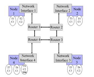 Figure 1: NoC with 4 nodes in a mesh topology.
3.2. Proposed HW mechanism
In order to define a mechanism supporting isolation, the network status is characterized by a global parameter named Severity. At certain time, the NoC will perform with a level of severity S in the range [1, Smax]. The isolation mechanism relies on the following two hypotheses:
- for a given temporal instant, only the messages sent by tasks with a criticality level can be transmitted by the NI and forwarded to the routers;
- the severity level can be modified, at run-time, by tasks that have specific privileges. These tasks (Task Masters, indicated as TM in Figure 1) are statically defined at design time.
At start-up, the system works in the least conservative mode, with a minimum severity level. If an anomaly condition is detected, and tasks with high criticality need to be executed, the system may switch to higher severity level, causing those tasks with higher criticality to access the network without competition with lower criticality ones. The following additional hypotheses are assumed:
- each NI can store the severity level of the network, to allow the transmission of new messages only if their criticality is greater or equal than S;
- the severity level of the network could be modified (raised or lowered) by a TM, by introducing inside the network a message which change the severity. This message is propagated to all network nodes and processed inside the NI. The reception of a message with a change in severity will activate an update of the severity level memorized inside the interface.
Being only the TM able to change the NoC Severity, the configuration of the system results to be protected: indeed, an untrustworthy entity is not able to change this configuration and possibly corrupt the system itself. The condition to prompt for a Severity change depends on the presence of anomalies: metrics able to indicate when an anomaly is verified can be defined, depending on the application executed on the NoC; then, by monitoring these metrics, it is possible to relate the TM transmission of a Severity change with the anomaly identification.
Observing Figure 1 and supposing that it is related to a scenario with two levels of criticality and two levels of severity, when the NoC possess a severity level equal to one, all the tasks can send and receive messages through the network. The routers could use a simple First-in First-out (FIFO) policy to manage the message forwarding toward the proper ports: when the FIFO is full, the message is rejected by the router, waiting for space in the queue. When a TM (T9 in the example of Figure 1) starts the procedure to change the level of severity of the NoC, all the NI shall be notified in order to update the corresponding value. When the severity level reaches the value of two, only T2, T6 and T9 are enabled to send messages while all the tasks will be able only to receive them. It is important noting that the designer owns the responsibility in order to eliminate, or to keep tolerable, conditions where a task cannot react to the message of a more critical one due to the NoC severity level possessed in that moment.
The reference HW design of the severity management mechanism, able to implement the isolation mechanism above described, is shown in Figure 2. It has an Input Buffer (called Message Buffer in the figure) to manage message traffic from the node: when a message from the node reaches the input of the buffer, the Comparator module checks if the criticality of the input message is greater or equal than the current network severity (stored in the Severity Register). If that is the case, the output of the comparator will be low, and the message will be stored into the Message Buffer. Otherwise, the output of the comparator will be high, and the message will be rejected: specifically, the loading of the message buffer will be inhibited, and a reject notification will be sent to the node. This functionality is described in the flowchart shown in Figure 3, where the methods fillInputBuffer(), Analyze(), StoreMessageBuffer() and Reject() implement, respectively, the reading from the node, the analysis of the received Message, the storage into the message buffer to transmit along the NoC and the rejection of the Message.
As above indicated, the aim of the proposed hardware mechanism is to assist the NoC design where, at a certain time, only the packets sent by a task with criticality greater or equal than the severity of the NoC are transmitted. The NI of nodes that executes the sending tasks blocks all other messages. It should be highlighted that this degradation is often tolerable in systems with mixed-criticality [17], as it eliminates any influence between lower and higher criticality flow. It can be noticed that the suggested solution does not reduce the number of criticality network levels. Also, it can be noticed that the proposed mechanism supports both spatial and temporal isolations: the former is ensured by the fact that only tasks with criticality greater than S can use the network resources to send messages. The latter is ensured by the fact that Severity can be changed over time, so giving the opportunity to all the tasks to access the network resource in specific temporal slots while still being able to assure that the most critical ones, when needed, can run without interferences due to less critical tasks.
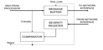 Figure 2: Implementation of the mechanism in a Network Interface (NI).
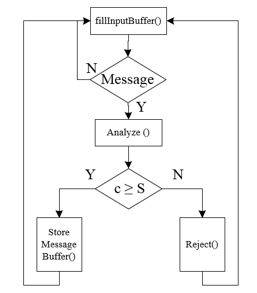 Figure 3: Functionality of the proposed HW mechanism.
4. HW Mechanism Design and Validation
This section presents the approach adopted to design and validate the proposed HW mechanism. The interests have been focused on three features: behavior validation, practicability check, and evaluation of the scalability. Regarding the first one, it allows to check if the developed mechanism behaves as expected. It is mainly based on HDL-based design and simulations. The second feature allows to check if this mechanism is possible to realize on real systems. It is based on a Hardware-In-the-Loop (HIL) approach applied to a simple NoC implementation on an FPGA platform. The final and third one (described in section 5) allows to check if it is possible to exploit the mechanism in real-size NoC. So, it is based on a Network Simulation approach to validate behavior and evaluate scalability, without the need to develop very complex NoCs. So, the following paragraphs, presents all the details needed to understand the performed HDL-based design and simulations activities.
4.1. Selected Reference NoC
A reference NoC has been considered for validation activities. It is an open-source NoC [19] described in HDL, that can be simulated and synthetized on FPGA. Such a NoC is of interest, since its design is very simple, allowing to reduce the number of required logic units for prototypal implementations. Moreover, it is provided with a MATLAB program to monitor the network traffic at run-time.
The reference NoC architecture consists of a network of nodes able to send and receive data, in order to complete their actions. Devices in nodes can be of different types, such as processors, memories and input/output devices. A network adapter is used to connect a device to a router, and a router connects the node to the rest of the network. Packet switching is used as a communication method across the network, with packets used as the communication medium.
Specifically, there are three types of packets in the network: write, read_request and read_return, as shown in Figure 4. All of them have a header, to indicate their type, and other fields depending on their goal.
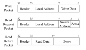 Figure 4: Packets of the reference NoC.
The write packet is sent by a master node to write data to a slave, while a read_request is sent by a master node to a slave one, and the latter replies with a read_return packet. write and read_request packets require a destination address: the reference NoC has a 32-bit address space, where the first 4 bits are used as the unique node IDs, while the remaining 28 bits are used for local addresses. The read_request packet also contains the source ID used by the receiver to send the read_return. read_return packets only contain the destination node ID of the source where they are replying to. A write_packet contains 8-bits of write data, while a read_return contains 8-bits of read data. The packets are sent over one clock cycle, rather than broken up over multiple clock cycles, to keep the hardware and logic simple.
Focusing on network adapter (NA), it represents interface between the node and the router, and its purpose is to convert signals from the local bus into a suitable packet format for the network, and back again. There are two types of network adapters and devices: master and slave. The master network adapter receives the following signals from the master device: write_address, write_enable, write_data and read_request. A master device can connect to the network adapter and the network should be totally transparent. The NA sends back not_ready, read_return and read_data. Any device wishing to connect to the network needs to handle a not_ready signal from the network adapter. Its output interface with a router is a packet_data_out. It can receive a busy signal from the router and a read_return packet.
Routers have five sets of channels connected to them, as shown in Figure 5. As the mesh organization is used in the network, four directions can be identified: north, east, south, west, and one additional channel going toward the local network adapter. The router is clocked with the global clock of the system. In order to move the packets around the network from sources to destinations, routers look at a special field of the incoming packets, called xy-counters [19]: they give priority to y-direction, firstly check in what vertical direction they should forward the packet, and then checking for the horizontal one. If a router receives a packet in which both x and y counters are set to 0, then it indicates that the packet was destined for that router and that it has now reached its destination (and should be forwarded to the local network adapter).
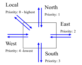 Figure 5: Router.
In order to support on debugging actions, a hardware monitoring system is offered together with the reference NoC [20] [21]. The monitoring system interfaces with an UART controller, allowing the communication with a host computer. A MATLAB program is also provided to be executed on host computer, providing a visual representation of the current traffic on the network, which is updated several times per second.
The proposed HW isolation mechanism has been integrated in an instance of the reference NoC discussed in the previous sub-section, composed of 16 nodes in a mesh topology, shown in Figure 6. Each device within a node is represented by a simple finite state machine that acts as a master or slave processor (in the following TP — Test Processor), executing some specific instructions.
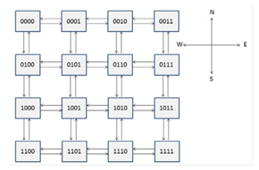 Figure 6: Reference 16 meshed nodes NoC.
In such a reference NoC, Severity and Criticality concepts have been introduced. If a TP tries to send a message with criticality less than current network severity, the message is blocked by NA. It is worth noting that messages are not blocked by routers, since, in this case, they are unaware of the isolation mechanisms. This improves portability but also means that, when a severity change occurs, all the packets already inside the networks are still able to freely circulate. In this case, they will be managed accordingly to their priority, as expected by the type of NoC. For validation purposes, Criticality, Severity and Priority have been set in the interval [0, 7]. In order to support the proposed approach, the NoC has been modified to introduce a fourth type of packet, called severity_change, shown in Figure 7. The goal of the packet is to allow a master task to trigger a severity change.
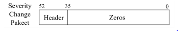 Figure 7: Packets managed by the reference NoC.
Together with the introduction of a new packet type, further assumptions have been done to reduce the management complexity of the network, focusing on the purpose of the tests:
- TM has been associated to the node in the upper-right corner of NoC shown in Figure 6. The corresponding TP is the only one able to change the severity of the network.
- Severity change requests are forwarded by following a snake-coil path, as shown in Figure 8. Routers forward such a packet only in one fixed direction
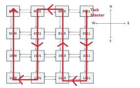 Figure 8: Snake-coil path.
Master and slave NA adopt a two-levels input buffer at both TP and Router side. By means of them and a proper busy signal, it is possible avoid losing input packets. If two packets are concurrently coming from TP and Router, they are managed at the same time, if possible, otherwise they are serialized giving priority to the one with greater criticality. As said before, the criticality/severity check is performed only in Master NA, specifically by checking the input buffer at TP side. This represents the major change with respect to the reference NoC. Another important one is that, if a message coming from TP is not accepted by NA, TP is notified by means of a proper msg_rejected signal. A detailed view on NA modifications is shown in Figure 9 and Figure 10.
The router is identical to the reference NoC one, apart from the need of improving the existing priority-based routing approach. In fact, in the case of concurrent packets forwarding, greater priority shall be given to criticality instead than to the port. It is worth noting that such a policy is simply priority-based, i.e., the router does not need to know about the criticality/severity mechanisms (in fact it is designed to work without knowing anything about the current severity level).
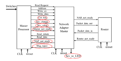 Figure 9: Modified master NA.
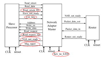 Figure 10: Modified slave NA.
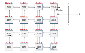 Figure 11: Simulated NoC.
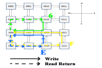 Figure 12: Write and read_return paths.
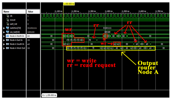 Figure 13: Packet forwarding in router close to node A
4.1. Validation by means of logical simulation
The above discussed NoC has been described in VHDL and simulated by means of Xilinx ISim [22]. In this way, it has been possible to verify the right forwarding of packets and the behavior of the proposed mechanism. In Figure 11, the simulated NoC is shown: it is composed of 16 nodes with different IDs (represented both in binary and hexadecimal base). Nodes 6, E and F are the master ones (i.e., they have a master NA and a master TP). In the considered test case, they perform some writings and readings by involving node 8 (slave). Written data (write_data) are composed of node ID and a progressive number (from 0 to 3, since, in the considered test case, each node performs 4 consecutive writing). In Figure 12, the main communication paths between the masters and slave node number 8 are shown.
Test 1 – Router packet forwarding
The first proposed test has the goal of verifying the correct packets forwarding done by routers. In Figure 13, it is shown the router close to master Node A managing input from ports N, E, and S, and forwarding them towards W (since all the write operations are related to node 8). The reported values represent the write_data field in hexadecimal base. In the presented test case, master NAs make use of their 3-bits ID LSB as criticality values for their sent messages; with this assumption, the following criticality values have been considered: criticality 6 for node 6 (110), criticality 6 for node E (110), criticality 7 for node F (111).
In Figure 13, it can be noticed that packets from nodes 6 and E reach the router with 1 clock cycle anticipation (since node F is far than the others). It is also possible to notice that the first two write packets (60 and e0), that requires the same output port, are correctly forwarded giving priority to the packet 60 (same criticality, but N port). Then, the newly arrived f0 is quickly forwarded, since it has greater criticality with respect to e0. The output is the sequence f0, f1, f2, f3. Since also the read_request packets form F have criticality 7, they are always forwarded in a single clock cycle (f0 is high for 4 clock cycles).
Test 2 – Isolation
In Figure 14, the isolation capability of the proposed mechanism is verified. Considering a severity level set to maximum value (i.e., 7) and stored by each NA, a TP tries to send a message with criticality less than the current severity. In particular, the TP tries to send 4 write and 4 read_request packets with criticality 6 (110); it receives the msg_rejected signal for 8 clock cycles. It is worth noting that, in this test, msg_rejected notifications are not managed in any way by the TP (e.g., no tentative resending).
Test 3 – Severity change
In Figure 15, a severity change in the NoC is shown. It is possible to notice the severity_change packet (highlighted in red) firstly sent by node 3 (the only allowed to do it, since it is supposed to be the only one to have a TM) to its NA. Then, such a command is forwarded to the whole NoC (following the path already shown in Figure 8), i.e., each NA updates its internal current severity value and setups a new message to forward the severity_change command to the next node.
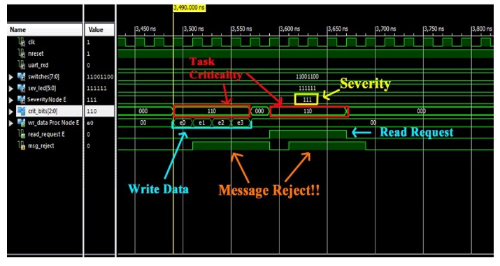 Figure 14: Criticality/Severity check.
4.2. HIL-based validation
In order to validate a prototypal implementation of the proposed mechanism, an instance of the reference NoC, enriched with that mechanism, has been implemented on a Xilinx Spartan-3 FPGA [23] using Xilinx ISE Design Suite 14.7 [24]. The testbed is shown in Figure 16. The prototype consists in a NoC with a 3×3 mesh topology, where each node device is represented by a master or slave Dummy Processor (DP), namely a simple finite state machine that acts as a processor executing some specific instructions. Such a network implements an 8-level Severity and Criticality system. To keep low the complexity, while focusing on proposed mechanism features, the TM has been associated to the node in the upper-right corner so that the corresponding DP is the only one able to change the severity of the NoC (actually, the corresponding dummy processor has been designed so that the user can manually decide when to do severity changes and at what value, by using board switches). Aside from the node at the top right that holds the Task Master, all other nodes have been randomly distributed between the two master and slave types, and the associated Dummy Processors have been configured to create a decent amount of traffic packets at all criticality levels in the network. Severity change requests are forwarded to the other nodes by following a fixed snake-coil path, as shown in Figure 17.
All packets are forwarded by routers with a Packet-Criticality based priority policy [19]: the routers first check in which vertical direction they should forward the packet, and then check for the horizontal one. If a router receives a packet in which both x and y counters are set to 0, then it indicates that the packet was destined for that node and that it has now reached its destination. If, at a given time, two or more packets from the input ports are destined to the same output port, a conflict occurs, and priority is given to the packet with the highest criticality, whereas other packets are blocked before they can be sorted out later. In the case of equal criticality, priority is given according to the input port of the conflict packets, by following the descending order: Local, North, East, South and West. It is worth noting that such a policy is simply priority-based, i.e. the router does not need to know about the criticality/severity mechanism (indeed it is designed to work without knowing nothing about the current severity level).
Master and slave NA adopt a two-level input buffer at both DP and Router side. By means of them and a proper busy signal, it is possible avoiding losing input packets.
After the system implementation on Spartan 3 FPGA, the monitoring system and the MATLAB program have been used to check the NoC status. Red wires indicate connections that have a lot of traffic, yellow ones indicate a small amount of traffic while white ones indicate no traffic at all. Other than the traffic, it is also possible to check the amount of busy and msg_rejected events. In Figure 18, it is possible to notice that with a low severity level (000) traffic is quite high, since all the nodes are able to send messages
After the setting of a severity change to the highest severity level (111) (the changing of severity using the TM is shown in Figure 17), the traffic appears to be heavily reduced, as shown in Figure 19. The area occupations are reported in Table 3. The impact is very small, so the adjective “lightweight”.
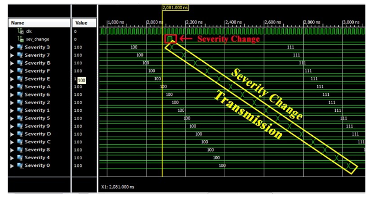 Figure 15: Severity Change.
Table 3: Area occupation.
| FFs | LUTs | fMAX | |
| Complete NoC with the proposed mechanism | 37 % | 70 % | 125 MHz |
| Proposed mechanism (area per each NI) |
1 (<1%) |
2 (<1%) | – |
| Proposed mechanism (area in 3×3 mesh) | 9 | 18 | – |
5. Scalability evaluation
In this section, a model of the reference NoC has been developed using the Omnet++ simulator [25] with the aim to evaluate the scalability of the proposed mechanism. The model of the NoC supports n-levels Severity and Criticality. Multiple standard (unprivileged) tasks and Master tasks can be statically associated to each node of the network, and different traffic patterns can be associated with each task. The simulator includes a statistic unit able to investigate the traffic sequences, and the possibility to use a flexible time base module able to model synchronous and asynchronous NoC. In the case of synchronous NoC, the model of the network makes use of a module (named the Time-base synchronizer) able to generate clock messages, ensuring synchronous communication between the various nodes. Other model features are the following:
- in a fixed, predetermined device, a single TM executes on the platform
- each router uses the xy routing strategy shown previously and the broadcasting of the Severity Change Packet;
- the TM can determine the traffic status and eventually its congestion, by inserting a special broadcast packet called the Inquire Packet (IP);
The TM will modify the severity by sending a Severity Change Packet if the measured congestion status exceeds a predefined threshold, or if there is a timeout elapse. This severity administration policy needs an additional overhead for the development of the routers, as every router should be capable to follow the number of queued packets and deal with the IP. Furthermore, the suggested enquiry strategy needs the insertion of additional packets inside the network, possibly disturbing with device traffic.
In Figure 20, there is the result of a simulation of the modelled system in case of a synchronous 8×8 NoC. This figure shows the total number of packets inserted into the network over time, reported in generic time units (i.e., number of clock cycles) and two indices of the network status: the number of queued packets at a certain time and the current network severity. It should be observed that the value of the two network indices is multiplied by one hundred for a better clarity of the figure. It can be seen that the traffic regulation mechanism is adequately capable to limit the traffic of the network in case of congestion, allowing only the successful transactions of high criticality messages in a timely manner: this shows the feedback that the proposed mechanism can provide when unexpected behavior from the tasks are verified.
In Figure 21, it is reported the number of total sent messages (red line) and the number of dropped messages (blue line). The number of dropped messages is lower than the total messages that go through the network. In particular, the number of total messages in the tested time interval is 4.14 ∙ 106, while the number of dropped messages is 3.00 ∙ 106.
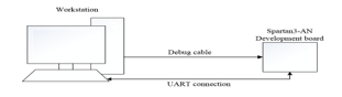 Figure 16: Testbed.
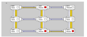 Figure 17: Snake-coil path.
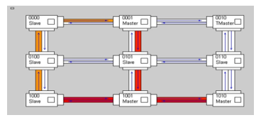 Figure 18: Network traffic with low severity (000).
 Figure 19: Network traffic with high severity (111).
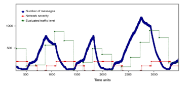 Figure 20: Simulation of a synchronous 8×8 mesh network.
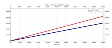 Figure 21: Number of total messages (red line) and number of dropped messages (blue line) for a synchronous 8×8 mesh network.
6. Further Analysis
Thanks to effort spent on creating a model, further analysis has been done by means of system simulations, introducing other aspects and evaluating a different broadcast strategy and a different management of the control traffic messages.
6.1. Different broadcast strategy
In this test, routers have the possibility of changing the broadcast of the Severity Change Packet. There are two possibilities:
- snake-coil strategy: the message, with TM in the node at the top right of the network, is broadcast one router at a time in a north-south direction, then moves one step to the left when the message reaches a router located at the northern or southern limit in the network itself and resume the journey in the north-south direction. The method is already described and used in the previous two sections.
- star-broadcast strategy: it takes its name from the design formed by the overall path travelled by the The origin node of the messages can be in any position. The first router forwards the packet to all the connected ports in order to reach the maximum number of routers. Routers located along the north-south axis respect to the first router forward the message to the east, west and north, if they received the message from the south, or forward it to east, west and south, if they received it from the north. Finally, the routers that receive the packet from the east [or west] forward the broadcast packet along the west [or east] direction in order to make the broadcast packet continue along the east-west axis (see Figure 22).
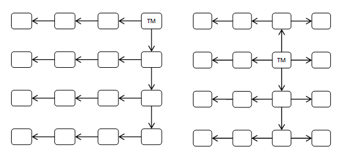 Figure 22: Star-broadcast strategy.
In Figure 23, it is shown the behavior of the system in case of a synchronous 8×8 NoC with the star-broadcast strategy instead of snake-coil one. As in previous section, the value of the two network indicators is scaled by a factor of one hundred for better clarity of the graph. Here, the TM periodically sends a control signal to which all routers respond by entering their own maximum queue value. In this period, the TM waits a maximum time equal to 10 clock cycles between one message and another before deciding to change the severity of the network. After this time, if the TM does not receive all the answers, then the network severity increases, trying to moderate the circulation of messages. Vice versa, when all the messages are received by the TM, the latter can decide to decrease the severity of the network. When all the messages are received, the TM in this test evaluates the average of the received answers.
The test shows that the proposed mechanism manages to control the flow of messages within the network, although the network itself is flooded with many control messages. The peak of messages reached within the network exceeds one thousand units, a situation in which the severity of the network is zero. In this case, there are several messages in the network and the TM fails to receive all the control messages, so the network severity is raised to one (one hundred in Figure 23).
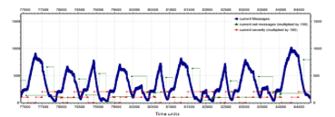 Figure 23: Simulation of a synchronous 8×8 mesh network without traffic control and with star-broadcast strategy
This leads to a decrease of messages in the network, but not enough so the TM causes another increase in severity. With severity two (two hundred in Figure 23), the severity does not decrease until the value answered by all nodes is less than a threshold value. The response received from all the nodes is averaged in order to obtain an indicative value of the network state. The value is considered only when the responses are received from all the routers. Subsequently, two tests are conducted on this type of broadcast strategy. The first one, shown in Figure 24, uses an exact average value obtained from all the responses received. In the second case, shown in Figure 25, the average is modified in correspondence of a minimum value in order to be higher.
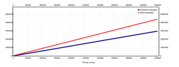 Figure 24: Number of total messages (red line) and number of dropped messages (blue line) for a synchronous 8×8 mesh network with star-broadcast strategy, exact average case.
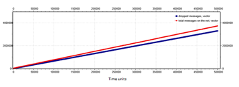 Figure 25: Number of total messages (red line) and number of dropped messages (blue line) for a synchronous 8×8 mesh network with star-broadcast strategy, modified average case.
Considering these two results, the network that performs best for message delivery time is the one that uses the modified average of traffic. However, this method results in a lower number of total messages sent over the network. Furthermore, with the use of the modified average, the maximum capacity of the routers results decreased in messages of a 20%.
6.2. Control traffic messages management
In this situation, devices and routers use two types of states to differentiate the type of messages processed, by extending the functionalities already present in the implemented NoC. Here, a single slot is dedicated to control traffic messages management. Two states have been identified:
- State zero indicates classic operation, i.e. read, write and reply messages are exchanged.
- State one only messages intended for traffic control are exchanged.
The traffic control messages in this type of network have a priority equal to that of the TM, in order to do not mix service messages with those of communication useful between the cores. Currently this functionality is supported only for a synchronous NoC. For a synchronous 8×8-node networks with control traffic messages management, the best behavior is obtained with the star-broadcast strategy (see Figure 26 and Figure 27). Here, there is a better delivery time for all messages.
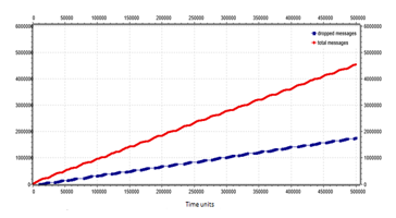 Figure 26: Number of total messages (red line) and number of dropped messages (blue line) for an 8×8 mesh network with control traffic messages management and snake coil strategy.
Analyzing all the experimental results for 64-node networks without control traffic messages management, the broadcast strategy that behaves best is the snake coil, unless the star-broadcast strategy modifies the average of the messages received. Therefore, if we consider the modified average, the star-broadcast improves and shortens the delivery time of the messages.
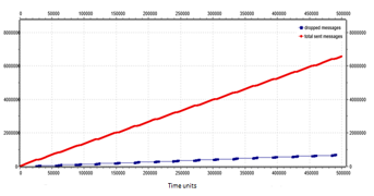 Figure 27: Number of total messages (red line) and number of dropped messages (blue line) for an 8×8 mesh network with control traffic messages management and star-broadcast strategy.
For the 64-node network with control traffic messages management, the best behavior is given by the star-broadcast. It must be remembered that, in the network with state, a fixed delay is introduced in the maximum time of delivery of the messages equal to the time of control necessary to probe the network. Despite this, the star-broadcast strategy keeps the average delivery time of messages low, even if it has a high delivery time.
7. Conclusions
Isolation is an important issue for embedded systems on which multiple tasks with different level of criticality are running. This paper has suggested a lightweight isolation mechanism to be introduced into existing Networks on Chip. This mechanism supports the execution of multiple applications with different criticality levels by supervising the packet exchange between network nodes. It does not reduce the criticality levels and it supports both spatial and temporal isolation. The system main innovation is its autonomy from the topology of the NoC and its easily flexibility among different NoCs. Small NoC implementations have been provided, showing the small impact in the area occupation, and motivating the adjective “lightweight”. Simulation on a network simulator has been proposed to evaluate the behavior of the mechanism on a NoC with more elements, and the feedback applied when there are unexpected situations is shown.
8. Future Works
Future works involve a further analysis to precisely characterize the overhead of proposed mechanism in a real existing NoC solution, and to investigate the best severity change policy. Moreover, given the outlined results, the possibility of adding a lightweight support for network status analysis will be explored as well.
Conflict of Interest
The authors declare no conflict of interest.
Acknowledgements
Authors would like to thank you Fabio Federici, Mattia Micozzi, Riccardo Cardinali and Biagio Iorio for the support on solving technical issues and precious feedbacks.
- A. Burns, R.I. Davis, “A survey of research into mixed criticality systems”, ACM Computer Surveys, 50(6):1–37, 2017.
- S.K. Baruah, S. Vestal, “Schedulability analysis of sporadic tasks with multiple criticality specifications,” in 2008 Proceedings of the 20th Euromicro Conference on Real-Time Systems (ECRTS), Prague, Czech.
- A. Agarwal, C. Iskander, R. Shankar, “Survey of Network on Chip (NoC) Architectures & Contributions,” Journal of Engineering, Computing and Architecture, 3(1), 2009.
- R. Kamal, N. Yadav, “NoC and Bus Architecture: a comparison”, International Journal of Engineering Science and Technology (IJEST), 4(4), April 2012.
- A. Achballah, S. Saoud “A Survey of Network-On-Chip Tools”, International Journal of Advanced Computer Science and Applications (IJACSA), 4(9), 2013.
- A. Esper, G. Nelissen, V. Nelis, E. Tovar, “How realistic is the mixed-criticality real-time system model?”, In Proceedings of the 23rd International Conference on Real Time and Networks Systems, RTNS ’15, pages 139–148.
- F. Federici, M. Micozzi, V. Muttillo, L. Pomante and G. Valente, “Simulation-Based Analysis of a Hardware Mechanism to Support Isolation in Mixed-Criticality Network on Chip,” 2017 European Modelling Symposium (EMS), Manchester, 2017, pp. 185-190.
- “AUTOSAR”. [Online]. Available: https://www.autosar.org/ [Accessed: 13-June-2019].
- “ARINC”. [Online]. Available: https://www.aviation-ia.com/ [Accessed: 13-June-2019].
- P. Ekberg, M. Stigge, N. Guan, W. Yi, “State-based mode switching with applications to mixed criticality systems,” in 2013 Proceedings of the 1st International Workshop on Mixed Criticality Systems (WMC), Vancouver, Canada.
- Andrew S. Tanenbaum and Herbert Bos. 2014. Modern Operating Systems (4th ed.). Prentice Hall Press, Upper Saddle River, NJ, USA.
- V. Muttillo, G. Valente, L. Pomante. 2018, “Criticality-driven Design Space Exploration for Mixed-Criticality Heterogeneous Parallel Embedded Systems,” In Proceedings of the 9th Workshop and 7th Workshop on Parallel Programming and RunTime Management Techniques for Manycore Architectures and Design Tools and Architectures for Multicore Embedded Computing Platforms (PARMA-DITAM ’18).
- R. Pellizzoni, P. Meredith, M-Y. Nam, M. Sun, M. Caccamo, and L. Sha, “Handling mixed-criticality in SoC-based real-time embedded systems,” in 2009 Proceedings Of the 7th ACM international conference on Embedded software (EMSOFT), Grenoble, France.
- H. Kopetz, A. Ademaj, P. Grillinger, and K. Steinhammer, “The time-triggered ethernet (TTE) design,” in 2005 Proceedings of the Eighth IEEE International Symposium on Object-Oriented Real-Time Distributed Computing (ISORC 05), Seattle, WA, USA.
- M. Schoeberl, “A time-triggered network-on-chip,” in 2007 Proceedings of the International Conference on Field-Programmable Logic and its Applications (FPL 2007), Amsterdam, The Netherlands.
- S. Tobuschat, P. Axer, R. Ernst, J. Diemer, “IDAMC: A NoC for mixed criticality systems,” in 2013 Proceedings of the IEEE 19th International Conference on Embedded and RealTime Computing Systems and Applications (RTCSA), Hakodate, Japan.
- A. Burns, J. Harbin and L. S. Indrusiak, “A Wormhole NoC Protocol for Mixed Criticality Systems,” in 2014 IEEE Real-Time Systems Symposium (RTSS), Rome, Italy.
- L. S. Indrusiak, J. Harbin and A. Burns, “Average and Worst-Case Latency Improvements in Mixed-Criticality Wormhole Networks-on-Chip,” in 2015 27th Euromicro Conference on Real-Time Systems (ECRTS), Lund, Sweden.
- G. Best, M. Birman, O. Rahnama, W. Pawlak. “Design and implementation of a simple mesh Network-on-Chip”. [Online]. Available: https://github.com/mattbirman/Network-on-Chip-in-VHDL [Accessed: 13-June-2019].
- G. Valente et al., “A Flexible Profiling Sub-System for Reconfigurable Logic Architectures,” 2016 24th Euromicro International Conference on Parallel, Distributed, and Network-Based Processing (PDP), Heraklion, 2016, pp. 373-376.
- A. Moro, F. Federici, G. Valente, L. Pomante, M. Faccio and V. Muttillo, “Hardware performance sniffers for embedded systems profiling,” 2015 12th International Workshop on Intelligent Solutions in Embedded Systems (WISES), Ancona, 2015, pp. 29-34.
- “ISIM”. [Online]. Available: www.xilinx.com [Accessed: 13-June-2019].
- “Xilinx Spartan3AN” Data Sheet [Online]. Available: https://www.xilinx.com/support/documentation/data_sheets/ds557.pdf, [Accessed: 24-May-2019].
- “Xilinx ISE Design Suite 14.7” [Online]. Available: https://www.xilinx.com/products/design-tools/ise-design-suite.html, [Accessed: 28-July-2019].
- “Omnet++”. [Online]. Available: https://omnetpp.org/, [Accessed: 13-June-2019].