
The Fusing Framework Between Lifting Carrier and Tractor-Trailer for Modern Transportation
Volume 4, Issue 4, Page No 522-528, 2019
Author’s Name: Ha Quang Thinh Ngo1, Thanh Phuong Nguyen2,a), Hung Nguyen2
View Affiliations
1Department of Mechatronics Engineering, HCMC University of Technology, Vietnam National University-Ho Chi Minh City (VNU-HCM), Vietnam
2Institute of Engineering, HCMC University of Technology (HUTECH), Vietnam
a)Author to whom correspondence should be addressed. E-mail: nt.phuong@hutech.edu.vn
Adv. Sci. Technol. Eng. Syst. J. 4(4), 522-528 (2019); ![]() DOI: 10.25046/aj040463
DOI: 10.25046/aj040463
Keywords: Robotics, Motion Control, Industrial Automation

Export Citations
The integrating model becomes one of key trends in engineering design. The more the product has functional specifications, the more the industrial consumer apply in many fields. In this paper, a fusion design of architecture platform for autonomous system is demonstrated. It is greater due to combining the specifications of various types in commercial market such as driving structure, multi-functional model or autonomous level. Therefore, plentiful advantages of systems are converged into one platform. From customer’s requirements, the system parameters and specifications are offered to consult during the process of design. To compare with previous works, the enhancement of tractor-trailer, lifting-carrier and auto-feeder using differential driving mechanism is merged successfully. The detailed design of prototype involves the development of hardware components and infrastructure. Later, the modeling of autonomous system is simulated on computer to meet the employed conditions. The force analyzing scheme helps to predict the working ability to complete their mission. To verify the proposed design, an experimental version of this system is tested in different cases. In mode of lifting carrier, the vehicle and cargo that become a rigid body, follow the reference trajectory in practical map. In another circumstance, vehicle plays a role as leader which take along with cargo, as follower. From these results, it can be seen that the proposed design is feasible, effective and capable in real world. In future works, a fleet of autonomous vehicles mixing multi-modes in the same map should be considered.
Received: 12 June 2019, Accepted: 06 August 2019, Published Online: 25 August 2019
1. Introduction
In the worldwide era, a large-scale system becomes more popular due to its huge advantages. Especially, in online shopping business, it needs a thousand of employers who work in distribution center or warehouse every day. Reducing the labor cost means that enormous profits are earnt. Therefore, the producer would always discover the methods to lessen the operating payment. One of common ideas is to use autonomous vehicle that carry goods to human operators [1, 2]. Various challenges had to be overcome in order to make this viable system, from design of robust autonomous vehicles, real-time communication, the coordination of vehicle and various control algorithms which permit the system to adapt and reconfigure itself leaning on the environment and working conditions. Generally speaking, grounded automated vehicle (GAV) is digested into several sub-categories. Authors in [3, 4] posed the lifting type of vehicle to elevate cargo in production site. The veridical product has three wheels including one driven wheel and two driving wheels. Two driving wheels of GAV have independent brush motors while the other is passive wheel. This model is very widespread nowadays since its movement is free and high loading capability.
The second one is forklift type with steering mechanism [5, 6]. This kind of vehicle often appears in port transportation, harbor storehouse or container yard. The main benefits are to provide heavy loading ability and powerful lifting mechanism. In most of its applications, it requires human to sit on. The diesel engine version is cheaper than one using electric engine. However, because its dimension is large, it needs more space to operate than others. In the other style of GAV, i.e. tractor-trailer transporter [7, 8], the long combination vehicle is gradually becoming more public in certain circumstances because of vantages related to decrease costs for material transportation and diminish fuel consumption. This research implements active trailer steering control to improve the maneuverability of long truck-trailer combinations. The problem of swept path width during cornering could be solved by nonlinear control strategies. The effectiveness of proposed approach is evidenced on experimental platform.
In reality, there is a need to integrate these above vehicles into a compact unit. The emerging trend helps to overcome the existing limitations such as particular control problems of model type, enhancing carrier, reducing shared workspace, improving low speed maneuverability and so on. Besides, the saving cost on buying an integrated platform is rather than separated ones. In this paper, we present a fusion design of automated vehicle in multi-applications. After the problem statement is given in Section II, the novel idea based on combining between lifting carrier and truck-trailer model is to provide many expandable developments. The study of proposed pattern that is demonstrated in Section III enables the modern mechatronics system design. Section IV performs the actualizing works in each type whenever vehicle adapts to different scenarios. Later, the verification of proposed design is proved through experimental tests of Section V. Finally, some conclusions about this approach are commented for further development in Section VI.
2. Problem Statement
GAV or autonomous robot which is energized by electric power, play the role as a potential means of transportation in future. Due to great rewards in logistics, e-commerce, factory automation, social service and in some situations, public carriage, it has attracted the attention of industry and academic. There are numerous forms of classifications in GAV, such as wheeled structure, driving mechanism or their purposes. Referring to four wheels and driving by front-side, authors [11] investigated the control scheme to realize the yaw moment in presence of unknown mismatched disturbances. An integral sliding mode control was embedded into differential drive assistance steering (DDAS) to guarantee the transient control performance. In the case of complete failure of active front-wheel steering system, a robust composite nonlinear feedback strategy [12] to achieve path following was studied in detail. Besides, by utilizing fault-tolerant control with DDAS, an innovative multiple-disturbances observer-based method was applied in considering the tire force saturations. With a variable speed integral PID controller and a coordinated control system based on adaptive weighting dependent vehicle speed [13], both the ideal steering wheel torque and expected yaw rate could be obtained. However, they are hard to employ in commercial market owing to unreachable real-time performance, especially in emergency stop case. Via driving mechanism in rear-side, some car prototypes have been commercialized effectively. The control problem seems to be more difficult since the leading angle is adjusted lately. Furthermore, the head of car is light weight. It tends to be unstable when running at high velocity. To be more flexible, four wheels of electric vehicle have been driven. In [14], the wheel driving torque on each motor could be modulated precisely and continuously to attain not only maneuverability but also energy-saving mode simultaneously. The distribution strategy of torque control using multi-objective optimization was categorized into high layer and low layer. Although the developed method was simulated, the effectiveness of this approach has not verified in experimental platform yet.
In the other configuration, the three wheels framework becomes one of key topics to develop. In [15], to decline the error dynamic stabilization problem, a nonlinear sliding mode control law is employed to surpass. The control organization is uniformly asymptotically stable if unknown disturbances and modeling uncertainties are bounded. It utilized the nonholonomic constraints and transitional trajectory to acquire feasible state trajectories. Though, in practical context, the mass changes incessantly and it is hard to measure inertial moment of whole system (vehicle and load) precisely. The most concern of two-wheeled configuration is balancing control algorithm. The reporters [16] analyzed a passive inverted pendulum model as an investigational device. The sampling effect of the digital control is simulated as a zero-order hold. The stabilization of the upright position is possible by choosing proper control parameters as function of the sampling period of the controller. There are many limitations such that nonlinear characteristics (friction, behavior of electro-mechanical) are not mentioned while they still occur in model. Also, the system coefficients are not prearranged exactly. Sometimes, the omni-directional mobile robot including four mecanum wheels was installed in manufacturing fields. The authors [17] introduced the design and development of omni-based robot orienting to intelligent factory. The upper sections are named as control level and application level while the lower one is chassis frame. Each modularized wheel was located on a vertical suspension mechanism to ensure the moving stability and keep the distances of four wheels invariable. In the unknown semi-structured indoor environment, the data from a Kinect visual sensor and four-wheel encoders were fused to localize the mobile robot using an extended Kalman filter with specific processing. The existing difficulties in the model are to eliminate the slipping phenomenon on mecanum wheel and restrict loading competence.
The other types of GAV are forklift truck and tractor-trailer vehicle. The prototype forklift is regularly applied in container yard, pallet-based storehouse or cold storage. The structure of forklift [18-20] entails of a single active rear wheel and two non-driven front wheels balanced in electric stacker. Around the automatic forklift, several sensing modules, for instance, positioning encoder, laser scanner or GPS-indoor are often attached to collect environmental information. The drawbacks of forklift robot are too dangerous to actuate in medium or small-scale area, high maintenance cost and inflexible motion. In the coordinated control approach [21, 22], a tractor-trailer vehicle could be ensured to track trajectory and maintain vehicle kinematics restriction and dynamics maneuvers simultaneously. In the level of kinematics, linear quadratic regulator and model predictive control were used to assess the posture controller separately. For dynamics analysis, sliding mode control and global terminal sliding mode control were inspected to design the dynamic controller for the tracking of the desired velocities generated online. Nevertheless, the viability and application of this method are still questioned.
As a result, the incorporated requirements become an inevitable trend in our era. The contributions in this paper are, (a) analyzing the fusing hardware of models between tractor-trailer form and lifting carrier form, (b) build up an experimental platform of GAV based on the analysis design positively and enforce it safely on working map.
3. Analysis of Fusing Model
Based on the new trend of fusion, multi-function should be merged various roles into one platform. For instance, the autonomous vehicle is able to elevate cargo in vertical direction and pull freight horizontally. The vertical lifting vehicle modeling is illustrated as Fig. 1. It is assumed that vehicle and freight become a rigid body which has total weight .
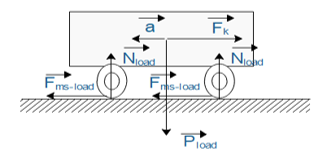 Figure 1: Forces act on lifting type model.
: acceleration of rigid body
: gravity force of rigid body
: reaction force on plane due to Newton’s law
: friction force between wheel and plane
: driving force from motors
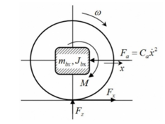 Figure 2: Analysis of driving wheel actuator.
According to second law of Newton, we have
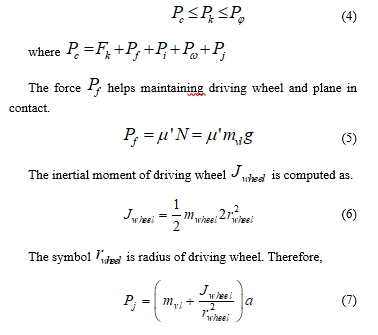
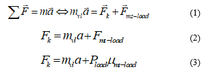 The force is estimated as 17,405 N approximately. It is considered that vehicle moves on high stiffness plane as Fig. 2. If there is no slipping phenomenon, then, the constraints of design parameters to avoid this problem must be met below condition.
Due to the movement on flat, the drag force could be cancelled. The volume of vehicle is small, hence, the air resistance force is ignored.
By choosing adhesion coefficient , the force is determined as.
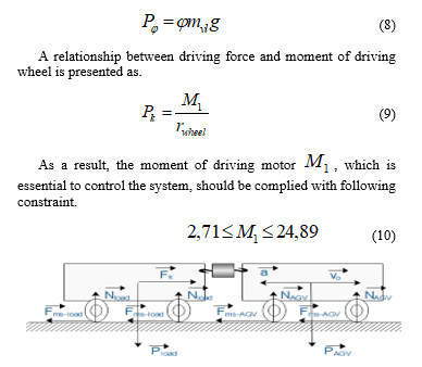 Figure 3: Forces act on tractor-trailer type model.
To certify the operation of truck-trailer type, an analysis of this modeling is shown as Fig. 3. The leader and follower are connected via a hook. The first vehicle is active drive while the other is passive one. In this case, we concern on interacting forces among them and angular driving wheels.
Theoretically speaking, the leader vehicle obligates to provide larger traction force to drive a chain of followers. This additional force is deliberated as . Thus, the new force that is necessary to drive whole system is denoted.
![]() Consider that it pulls the followers not greater than its weight. Adding the safe ratio as our experiences, the new force could be rewritten as.
Consider that it pulls the followers not greater than its weight. Adding the safe ratio as our experiences, the new force could be rewritten as.
![]() Besides, the factors (material, structure or inside components) of driving wheel would affect on adhesion coefficient . The estimated moment of driving motor is renewed as.
Besides, the factors (material, structure or inside components) of driving wheel would affect on adhesion coefficient . The estimated moment of driving motor is renewed as.
 4. Fusion Design in Proposed Hardware
In this section, the detailed design of proposed model is mentioned. Fig. 4 shows the inside frame of mechanical parts in vehicle. Generally speaking, the architecture of system is classified into three main layers (base, middle and lifting layer) and one intermediate layer. The base layer is the lowest one and stiff enough to bear the entire mass of whole system. The driving mechanism connoting DC motors with gears, drivers, soft couplings, battery, electric cylinder and so on, is located on base layer. Four rolling actuators that are hang on middle layer play a role as feeding actuator automatically. One electric cylinder is situated at center of the middle layer to upraise goods. Eventually, the lifting layer is at top. The electromagnetic lock, dwelling in this layer, is exploited to pull load horizontally. The intermediate one is a framework for holding and suspending among layers.
1-Driving wheels
2-Bearing
3-Soft coupling
4-Jig of motor
5-DC motor
6-Caster wheel
7-Loadcell
8-Shaft of intermediate layer
9-Battery tray
10-Electric piston
11-Inductive proximity sensor
12-Linear actuator
13- Electromagnetic lock
14- Lifting layer
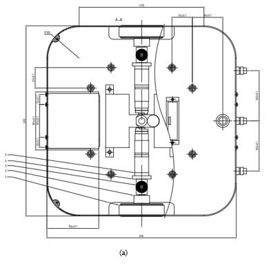
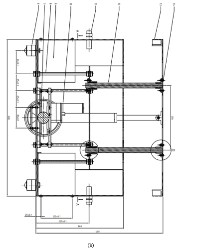 Figure 4: Vertical view (a) and horizontal view (b) of hardware structure design.
 Figure 5: Diagram of data and control bus in proposed system.
Fig. 5 demonstrates the threads of data transmission and elements of control scheme in proposed system. It is powered by 32-bit MCU up to 168 MHz with floating point unit, 1 Mbyte flash memory, 192 Kbyte RAM, various I/Os, three channels of 12-bit ADC, two channels of DAC providing high performance and wide range of applications. For the internal signals, the data bus accommodates exchanging information (sensors or network protocol) whilst the control bus encompasses synchronizing interface (actuators, drivers). Due to centralized control method, the system is effective, reliable highly and simple to debug. However, to enlarge the real time performance, the coding needs to be optimized in firmware level.
The navigation problem of vehicle is also an attractive issue in control of system. The Radio Frequency Identification (RFID) technology is involved to lessen the burden data transmission. In each crossroad or corner, RFID card is occupied under the line guide. In the bottom side of vehicle, the card reader is stayed at central point to read and notify the unique code to host computer. The operator, who sits in center control room, could determine where the system locates in working map.
5. Research Results
It has been known that the combining approach must deal with various challenges and the gap between computational design and real world should be as small as possible. Henceforth, the system is validated experimentally in real scenario shown in Fig. 6. The architecture of control topology consists of local controllers and central one. The main microprocessor in local controller is powerful with high computing ability, fast processing and expandable peripherals. The host personal computer is with i7 core, high speed clock and visual monitoring capability. The supervisor would stay in control area to supervise the operation of system. The local controllers and central manager are contacted via wireless communication. The control messages are unceasingly transferred among them to prevent unfortunate incident.
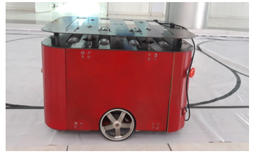 Figure 6: Experimental model of proposed vehicle.
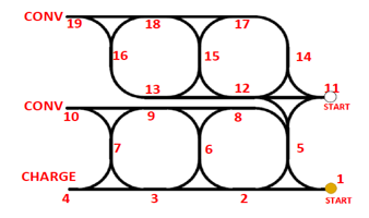 Figure 7: Overview of mapping area in workspace.
To imitate the practical situations in factory or distribution center, an overview of mapping working sector is drawn in Fig. 7. For multi-agent system, there are two reference regions are in parallel to enhance industrial productivity. The start points, charging section and conversing node are formed to offer various circumstances. At initial stage, vehicle moves to cargo’s location and bring to target position. In the case that the cargo must be out of storage, vehicle takes to conversing node. The battery management is gathered at charging station. Whenever level of energy is low, autonomous vehicle sends a notification to host server and move to charging node.
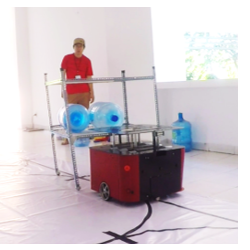 Figure 8: Experimental test scenario of tractor-trailer model.
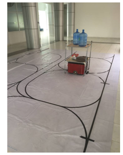 Figure 9: Experimental test scenario of lifting model.
The shelf of cargo is made of steel and its height comply with industrial standard. There are only two floors, but its floors can be extendable. Four caster wheels are attached under the shelf to assist the free motion. The experimental validations include two-fold: first, vehicle begins at start point, it passes serial points to target position. Then, the lifting layer is gone up as height as the bottom floor of shelf. At that moment, the local controller activates electromagnetic lock to maintain force. It drives the shelf according to reference path as Fig. 8. The reverse process is actuated in target position: inactivate the electric lock, lift down and gradually move to next position.
Sequently, the lifting mode is experimented as Fig. 9. In this case, the autonomous vehicle is compelled to accomplish the mission: brings the rack of payload from initial position to final location. Launching at start point, it comes to site of shelf by tracking linear and circular path. Later, vehicle orders lifting part to move up elevating the shelf. At this time, vehicle and cargo become a rigid body. Both of them are conveyed to final place and released there. The grounded robot could come back start point and ready for next task.
Table 1: Comparative Tracking Error Results in Experimental Tests
| Test case | RMS | Average |
| Lifting model | 0.157 | 0.268 |
| Truck-trailer model | 0.082 | 0.194 |
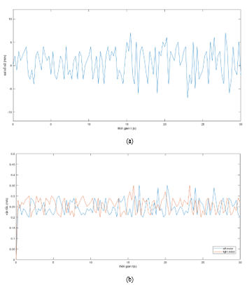 Figure 10: Experimental performance of truck-trailer model, (a) tracking error, (b) velocity of left wheel and right wheel.
The monitoring parameters in this study are tracking errors and control speeds. In differential drive, the variations in velocity of left and right wheels have an effect on directional movement. The tracking error governs the output performance in whole system. Fig. 10 and Fig. 11 show experimental results in two case studies respectively. In truck-trailer test, the leader must take a follower behind carefully. The motion of trailer affects on tracking error of front-runner. If leader moves so fast, it tends to deviate from reference path at corner. Otherwise, the force is too small to steer a follower or time-consuming motion costs too much.
In lifting test, the weight of whole system including total mass on shelf plus itself is heavier. Consequently, the motion seems to be more difficult. The value of tracking error, in this scene, is larger than others while the velocities of wheels are adjusted continuously. To visualize the differences in two cases, Table 1 reports the tracking error (Root-Mean-Square value and average value). From these results, it could be seen obviously that tracking error in lifting mode is larger than one in truck-trailer mode. The reason is that the control scheme drives harder when vehicle and cargo become a rigid body.
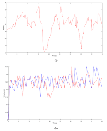 Figure 11: Experimental performance of lifting model, (a) tracking error, (b) velocity of left wheel and right wheel.
6. Conclusions
In this paper, a multi-purposes implementation for autonomous grounded vehicle is fused into an unique framework in practical factory. The proposed design is feasible, low cost and complies with industrial solicitations whilst it still conserves flexible motion. Furthermore, the integrating approach ensures that it is not only useful in various applications, but also it provides wide development trends, such as smaller, smarter or more convenient. From the successful results of research, it could be achievable in logistics, manufacturing industry, material transportation and training.
Conflict of Interest
The authors declare no conflict of interest.
- R. D’Andrea and P. Wurman, “Future challenges of coordinating hundreds of autonomous vehicles in distribution facilities” in IEEE International Conference on Technologies for Practical Robot Applications, 2008, https://doi.org/10.1109/TEPRA.2008.4686677.
- H. Q. T. Ngo, T. P. Nguyen and H. Nguyen, Research and develop of AGV platform for logistics warehouse environment; Vancouver: Springer-Verlag, 2018, https://doi.org/10.1007/978-3-030-02683-7_32.
- D. Chen, Z. Shi, P. Yuan and Z. Li, “Trajectory tracking control method and experiment of AGV” in IEEE Advanced Motion Control, 2016, . https://doi.org/10.1109/AMC.2016.7496323.
- V. Q. Nguyen, H. M. Eum, J. S. Lee and C. H. Huyn, “Vision Sensor-based Driving Algorithm for Indoor Automatic Guided Vehicles,” International Journal of Fuzzy Logic and Intelligent Systems, 13(2), pp. 140-146, 2013.
- T. A. Tamba, Q. T. T. Bui and K. S. Hong, “Trajectory generation of an unmanned forklift for autonomous operation in material handling system” in SICE Annual Conference, 2008, https://doi.org/10.1109/SICE.2008.4654955.
- J. X. Xiao and F. L. Lu, “An improvement of the shortest path algorithm based on Dijkstra algorithm” in International Conference on Computer and Automation Engineering, Singapore, 2010, https://doi.org/10.1109/ICCAE.2010.5451564.
- P. Ritzen, E. Roebroek, N. van de Wouw, Z. P. Jiang and H. Nijmeijer, “Trailer steering control of a tractor-trailer robot,” IEEE Transactions on Control Systems Technology, 24(4), 1240-1252, 2016, https://doi.org/10.1109/TCST.2015.2499699.
- M. A. Guney and I. A. Raptis, “A robotic experimental platform for testing and validating warehouse automation algorithms” in International Conference on Technologies for Practical Robot Applications, MA, USA, 2015, https://doi.org/10.1109/TePRA.2015.7219693.
- C. T. V. Kelen, P. M. G. Jorge, S. B. Thales, C. A. Roberto, M. S. Rafael, B. Marcelo and A. P. C. Glauco, “Robotic forklifts for intelligent warehouses: routing, path planning and auto-localization” in International Conference on Technologies for Practical Robot Applications, Vina del Mar, Chile, 2010, https://doi.org/10.1109/ICIT.2010.5472487.
- H. Q. T. Ngo, T. P. Nguyen, V. N. S. Huynh, T. S. Le, C. T. Nguyen, “Experimental comparison of complementatry filter and Kalman filter design for low-cost sensor in quadcopter,” International Conference on System Science and Engineering, pp. 488-493, 2017, https://doi.org/ 10.1109/ICSSE.2017.8030922.
- C. Hu, R. Wang, F. Yan, Y. Huang, H. Wang and C. Wei,”Differential steering based yaw stabilization using ISMC for independently actuated electric vehicles,” IEEE Transactions on Intelligent Transportation Systems, vol. 19, no. 2, pp. 627-638, 2018.
- C. Hu, R. Wang, F. Yan and H. R. Karimi,”Robust composite nonlinear feeback path following control for independently actuated autonomous vehicles with differential steering,” IEEE Transactions on Transportation Electrification, vol. 2, no. 3, 2016.
- T. Chen, X. Xu, Y. Li, W. Wang and L. Chen, “Speed-dependent coordinated control of differential and assisted steering for in-wheel motor driven electric vehicles,” Proc. of the Institution of Mechanical Engineers Part D: Journal of Automobile Engineering, vol. 232, no. 9, pp. 1206-1220, 2018.
- C. Lin, Z. Xu, “Wheel torque distribution of four-wheel-drive electric vehicles based on multi-objective optimization,” Energies, vol. 8, no. 5, pp. 3815-3831, 2015.
- H. Ashrafiuon, S. Nersesov, G. Clayton, “Trajectory tracking control of planar underactuated vehicles,” IEEE Transactions on Automatic Control, vol. 62, no. 4, 2016.
- B. A. Kovacs, G. Stepan, Z. Wang, T. Insperger, “On the stability of two-wheeled vehicle balancing passive human subjects,” 12th IFAC Symposium on Robot Control, vol. 51, no. 22, pp. 337-342, 2018.
- J. Qian, B. Zi, D. Wang, Y. Ma, D. Zhang, “The design and development of an omni-directional mobile robot oriented to an intelligent manufacturing system,” Sensors, vol. 17, pp. 1-15, 2017.
- D. Ilangasinghe, M. Parnichkun, “Navigation control of an automatic guided forklift,” 2019 First International Symposium on Instrumentation, Control, Artificial Intelligence and Robotics, pp. 123-126, 2019.
- H. Q. T. Ngo, Q. C. Nguyen, T. P. Nguyen, “Design and implementation of high performance motion controller for 2-D delta robot,” Seventh International Conference on Information Science and Technology, pp. 129-134, 2017, https://doi.org/10.1109/ICIST.2017.7926505.
- J. L. Syu, H. T. Li, J. S. Chiang, C. H. Hsia, P. H. Wu, C. F. Hsieh, S. A. Li, “A computer vision assissted system for autonomous forklift vehicles in real factory environment,” Multimedia Tools Applications, vol. 76, no. 18, pp. 18387-18407, 2017.
- Ngo, Ha Q.T.; Phan, Mai-Ha. 2019. “Design of an Open Platform for Multi-Disciplinary Approach in Project-Based Learning of an EPICS Class.” Electronics 8, no. 2: 200.
- M. Yue, X. Hou, R. Gao, J. Chen, “Trajectory tracking control for tractor-trailer vehicles: a coordinated control approach,” Nonlinear Dynamics, vol. 91, no. 2, pp. 1061-1074, 2018.