
Embedded Artificial Neural Network FPGA Controlled Cart
Volume 4, Issue 4, Page No 509-516, 2019
Author’s Name: Mohamad Faiz Ahmad, Syed Sahal Nazli Alhadya), Ooi Zhu Oon, Wan Amir Fuad Wajdi Othman, Aeizaal Azman Abdul Wahab, Ahmad Afiq Muhammad Zahir
View Affiliations
School of Electrical and Electronic Engineering, Engineering Campus, Universiti Sains Malaysia, 14300 Nibong Tebal, Pulau Pinang, Malaysia.
a)Author to whom correspondence should be addressed. E-mail: sahal@usm.my
Adv. Sci. Technol. Eng. Syst. J. 4(4), 509-516 (2019); ![]() DOI: 10.25046/aj040461
DOI: 10.25046/aj040461
Keywords: Artificial neural network, Color code, Field programmable gate array, Mobile robot, Multilayer perceptron, Root mean square error, Verilog HDL

Export Citations
An artificial neural network (ANN) computing system can be significantly influenced by its implementation type. The software implemented ANN can produce high accuracy output with slow computation time performance compared to hardware implemented ANN which runs at a faster computation time but with low accuracy. Normally, software implementation reduces the proficiency and efficiency of the model. Robot performance plays an important role as it needs fast response to process information that is applied with ANN. As a consequence, the proposed research focuses on comparison between hardware and software implementation multilayer perceptron (MLP) for cart follower in Field Programmable Logic Array (FPGA). Both of the software and hardware models produced the same precision where the output distance at angles -10°, 0° and 10° shows same percentage error. Besides that, both of the models have similar root mean square error (RMSE) which are 0.469, 0.479 and 0.267 at -10°, 0° and 10° respectively. The processing time of MLP model implemented in hardware and software are at 1.91μs and 78.06μs respectively. Thus, it can be concluded that hardware implementation is better than software implementation.
Received: 02 June 2019, Accepted: 16 August 2019, Published Online: 23 August 2019
1. Introduction
The concern of societies in creating a quality of life for everyone has become prevalent. Therefore, lots of research on creating infrastructures and tools to ease the daily activities of people are fostered. This has led to the research on designing and fabricating of robots. In this technological era, the world is making a great stride towards autonomous systems. An autonomous system is referred to as a system that is capable of operating in the real-world environment without any external controls. It can maintain its internal structures and processes for extended periods and capable to adapt toward environmental change. The overall architecture of the robot consists of sensors, actuators and intelligent processors [1].
Autonomous robotic vehicle is able to perform intelligent motion and action without guidance or tele-operator control. It is used for remote repair and maintenance, a motorized system for office and factory and even an intelligent wheelchair for the handicapped [2]. It is also known as a mobile robot or embedded robot. After a long research, the mobile robot today is smaller with numerous actuators and sensors controlled by inexpensive embedded computer system as a processor [3].
Visual tracking is commonly utilized in a various of robotic applications that need the localization of moving target like machine learning, human machine connection and robot navigation. It proposes object tracking through the literature and algorithm based on the particular cue observation like edges, color and feature templates. Each of the cues can provide reliable tracking under limited conditions [4].
Artificial neural network (ANN) is defined as an operation of a biological ANN system [5]. It makes the computer able to simulate a human in processing the data and behave intelligently in some ways like pattern recognition. It gathers all the information pattern based on the input data and produce a desired result. The production of ANN can be concluded as a process that gathers enough knowledge to produce a model with a correct sequence of the rules that satisfies the expected condition.
ANN comprises of data collection, data analysis and decision making with different approaches in each stage [6]. ANN can be used to control the physical actions of a mobile robot which enable it to navigate through the environment and manipulate items and solve other situations. The production of ANN can be characterized as a search process to search for the correct sequence of rule as control strategy with enough knowledge in a database to produce the termination condition [7].
The main purpose of this research is to perform MLP implementation into FPGA and evaluate the network performance. Therefore, the following objectives are being set to achieve the aim of this research:
- To perform MLP implementation of ANN into FPGA.
- To compare the performance of MLP implemented hardware and software in FPGA.
The embedded MLP data in FPGA is only used as a tool to implement the operating system of Cart Follower using the FPGA. So, any data from the MLP is only used as a reference. The research mainly focuses on data comparison between MLP hardware and software implementation in FPGA. Thus, an analysis on both type of implementations will be obtained and discussed.
2. Literature review
2.1. Mobile robot
There are several mobile robot-based localization methods present which can be roughly divided into 2 general classes. The first class is without its local position information. It keeps track of the robot’s position to enable localization. The second class is with its local position information. It uses the global position estimate to enable localization. For the mobile robot in the second class, it is normally equipped with GPS for localization and estimate the distance (indoor positioning tracking) [8]. For the mobile robot in the first class, it can be described as following to keep track or follow object. Examples of the robot are leader following, human following, line or path following and sound following. The method to achieve the task of following might vary in the hardware or sensor used. Ghandour et al. [9] came out with a collision avoidance mobile robot based on human interaction. Kinect sensor with motion identification became an interface for humans to interact with. The robot will navigate directly to the target if there is no human around for interaction process.
CMUcam used as a tracking sensor contributed to a successful autonomous mobile robot. The taken value of camera’s field of view (FOV) with several details from other sensors gathered as well to establish the robust tracking system [10-13].
Leader following robot is mobile robot that follows the command of the leader robot. It can be used as an active signal positioning machine to discover and track the leader position [14]. The leader robot works together with all its following robots to move the box. AI follower forces will synchronize with the direction of the force applied by the one leader robot although there is no communication between the follower robots [15].
Human following robot has an ability to coordinate the human motion in a populated, continuously changing, natural environment. For Prassler model, Velocity Obstacle approach is applied for motion planning amongst moving obstacles. Besides, the model also tracks the virtual target to manipulate the direction and velocity of the robot’s movement according to the person it follows [16]. For ApriAttenda model by Yoshimi, it uses the image processing to define region of interest. Then it recognizes the texture and color of the subject. The specific person is then detected from the specification and the human position is calculated. Stereo vision with systemizing visual and motion control helps to grab the details on the distance to each features like color, targeted speed and point for a stable tracking in many situations [17]. Line or path following robot is route-based following robot. It uses line tracking method with the implemented Infrared Ray (IR) sensors. The IR sensors was set up and distributed according to its position and informing the line location to maneuver the navigation [18].
Another type of following robot is sound following. It can detect the presence of human based on specific sound frequency. Luo et al proposed a mobile assistive companion robot that used laser and vision sensor to follow the aimed person. The robot was made up of a laser range finder, a tracking camera and a microphone. It contains lot of sound source recording system to perform an interaction with human. This function is useful to detect the user if the robot lost its tracking path. The microphone’s function was to grab the sound wave in time delay of arrival (TDOA). The laser finder was used to detect the lower part of human and the camera was used to track the upper part of human [19].
The optimization of ANN with the trajectory tracking control system proposed lead to enhancement of orientation and motion control of autonomous vehicle’s performance. The trained evaluator manages to acknowledge both linear and nonlinear systems behavior due to ANN structure that allows complex variables mapping [20]. In an instance, the increment of the system performance is only temporarily boosted for a certain time.
2.2. FPGA cart follower
Field Programmable Gate Arrays (FPGA) are advanced microprocessor created to be programmed by the user [21]. It contains a sets of configurable logic blocks (CLB), multiplexers, look table and flip flops. CLB provides physical support for the program downloaded on FPGA [22]. Hence, it supports the sequential functions and complex computations [23]. ANN implementation in FPGA is possible as it preserves the parallel architecture of the neurons in a layer and offers flexibility in reconfiguration. FPGA maintains high gate density which is needed to utilize the parallel computation in an ANN [22]. Most of ANN are implemented in software. A project, “Investigation on MLP ANN Using FPGA for Autonomous Cart Follower System” [24]. This project shows that the hardware floating-point acceleration block increases the logic element resource utilization. This project focuses more on the system on chip (SOC) design but not on hardware implementation. Software configuration has the advantage of being easy to implement but with poor performance. Hardware configuration is generally more complex to be implemented but with better performance.
2.3. Artificial neural network
ANN ideas came from computer programs engineered to mimic how human brain thinking and making a decision [25]. ANN is one of the main tools used in machine learning. A simple neuron made up of three layers, which are the input layer, hidden layer, and output layer [26]. Figure 1 shows an ANN MLP model.
- Input layer: This layer is responsible for receiving signals, information (data), and features from the external environment.
- Hidden layer: These layers will extract patterns in neurons and analyzing the processor system. It transforms the data from the input layer to the output layer as a final product.
- Output layer: This layer is responsible for creating the final outputs, which the processed neurons in the hidden layer.
There are two main procedures in design ANN which are forward process and backward process. Feedforward ANN is known as data-driven. It defines the number of layers, the number of neurons in each layer, what kind of training method and activation function are selected, and then passes input data through the network. Backpropagation ANN is known as goal-driven. It defines the loss function to calculate the gap between the prediction value and the labelled values. It looks for the minimum value of the error function in weight space using gradient descent [27]. The weights will get updated to optimum weights. One feed forward and back propagation process can be called as one epoch and a trained ANN model need hundreds or thousands of epochs.
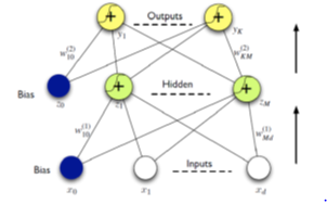 Figure 1: ANN MLP model
2.4. Hardware ANN FPGA implementation
Wibowo et al. [28] presented of the hardware implementation ANN algorithm in FPGA to solve reconfigurable computing (RC) issues. Speed and space are two main factors to be considered on performing parallel processing method. The processing speed rely on time taken by the route and logic gates meanwhile space rely on FPGAs component utilization. The ANN can be illustrated as a proportional graph composed of multiple edges. It functions as a communicator to send information to other parts through weighted connections. The FPGA has reached a successful penetration in various domains. The improvement could be made by adding activation function components to further increased the processing speed.
Gaikwad et al. [29] proposed a hardware implemented FPGA for military equipment that uses an MLP algorithm to perform classification tasks. Parallel MLP computation was implemented to reach enhanced hardware design. The evaluation of the overall system has been made by UCI dataset with 20 samples. The training, validation and testing process was held on 10 different MLP models. The time taken for classification was 270 ns and used 120 mW of power. The result shows that the performance efficiency was better than other hardware MLP implementation in FPGA in term of processing time.
Zeng et al. [30] presented a worldwide embedded hardware implementation ANN to balance the parallel connected current suppression. The focusing part is on control execution and strategy. The ANN was adapted with PID controller to yield the characteristics of the current suppression. It can be refined automatically to control the PID parameters based on various real world feedbacks and fit with linear and non-linear current. The analysis on ANN-PID shows that there was 0.023% of mean error in current control and the performance was increased up to 5.5 times as the load expanded.
2.5. Software ANN FPGA implementation
Jia et al. [31] proposed a mixed gas online detector instrument based on ANN algorithm in FPGA software implementation to detect natural gases. The proposed method can simply acknowledge the concentration of three different gases that are mixed together and separate them individually by back-propagation (BP) MLP ANN technique. The gases compositions were measured by infrared gas sensors due to its long life and fast response. FPGA has an advantage in solving parallel computation in a small size with quick response. The BP MLP ANN technique was attached with FPGA. The results show that the three gases maximum error were reduced from 0.64% to 0.27, 1.02% to 0.32 and 1.34% to 0.42% respectively. The response time taken for the proposed method to separate three gases completely is about half minute.
Cedano et al. [32] came out with a configurable architecture for ANN with FPGA in an SOC implementation. They used Multilayer Feedforward NN (MFNN) to produce the transfer functions. This architecture depends on memory blocks, multiplexers and single perceptron that enable the information collecting process. Extended kalman filter has been used to obtain the best weight values for the MFNN. The function blocks in the FPGA for configuring the MFNN was controlled with SOC microprocessor. The result shows that the generalization of root mean square error (RMSE) obtained for uncertain inputs was -32.82 dB. However, the desired resources by a custom implementation were directly proportional to the MFNN size.
3. Proposed methodology
3.1. Overall scheme
The beginning of the project started with literature review on previous researchers. This showed ANN embedded systems. After that, the proposed MLP algorithm was presented to obtain the best weights and biases throughout the network. For instance, the model for activation function was proposed to enable the learning process of complex mappings between the inputs and response variables. The sequences were proceeded with software and hardware implementation after the model was tested. The proposed model was then simulated with MATLAB. Debugging was done if the output is not close to the targeted output. At the last, an analysis was carried out on both software and hardware implementation model in FPGA and the performance for both implementations were then compared. Figure 2 shows the general flow chart of the research.
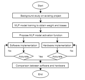 Figure 2: General flow chart of the research
3.2. Data acquisition
The color code (CC) will vary according to x and y axis. The CC has been placed at 30cm from ground level as it was the desired position for tracking camera of cart follower. CMUcam5 will illustrate the cart meanwhile the targeted illustrated by CC from 20cm to 69cm. The perpendicular distance is variate for each centimeter. In addition, angle of the CC has been chosen as manipulated variable to determine the movement of the CC to the right and left. Figure 3 shows the experimental set up of data collection. The step size for the angle is 5o. Table 3 shows the range of angles according to the distance. Each manipulation of distance and angle between the camera and color pattern obtained a different set of raw data. These raw data were used to train the model of the ANN in order to generate the weights and biases used to predict the output distance and angle.
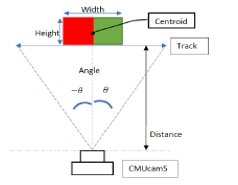 Figure 3: Experimental setup for data acquisition
3.3. Data training
The proposed model made up of three layers. They are input, hidden and output layer. Backpropagation MLP is used to update the overall system. Weights and biases are improved until ideal value has been reached. Cost function is used to figure out the expected output and pathway to enhance the weights and biases. The RMSE value is reduced throughout the training processes. The gradient function is decided from MLP which associated with reverse computation and plays an important role in balancing the weights and biases. The output for the MLP system can be shown by dot product Y=W.X where Y is the final output, W is weight and X is a vector. The system will efficiently worked if the weights are ideal and the training is well converged.
3.4. Simulation of MLP model
After the weights and biases have been obtained, the entire model was simulated to evaluate the model endurance. Raw data was directly fed into the input block as well as to the ANN function block and creating the desired output of distance and angle. An evaluation of the system reliability has been made from the output for error test analysis. Figure 4 shows the Simulink block diagram for the MLP model.
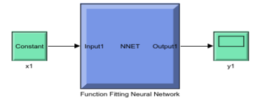 Figure 4: Simulink for the MLP model
3.5. Hardware implementation of ANN in FPGA
The hardware implementation was performed by using Verilog HDL language. Each implemented block represents as a CLB. The blocks are separated into branches due to multi-operation point of IP block. There are two output blocks due to two final output desired by the designed model. Figure 5 shows the MLP model block diagram.
The multi-cylce of IP block foating point can run in parallel. The sequential state operation relying on the start and done signal. Both start and done pins of the block indicate as the start and end of arithmetic computations respectively. If all of the IP block start signal simultaneously, it is considered parallel while programming to use done signal after to feed to other IP block can consider sequential. Single HDL code compilation can contain multiple start and done signal. Figure 6 shows the IP block for multi cycle floating point used for various float number computation in FPGA. 10 hidden layer networks were being fed into the output layer due to 10 hidden neurons (HN) used. Figure 7 illustrate the overall layer of the HN output block diagram.
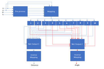 Figure 5: MLP model block diagram
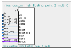 Figure 6: IP block for multi cycle floating point
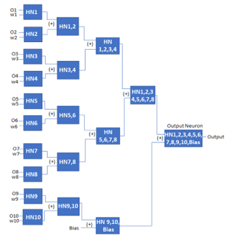 Figure 7: FPGA HN layer block diagram for one output neuron
3.6. Software implementation of ANN in FPGA
The system consist of a clock to sample data, a NIOS 2 processor was used to grab the C Code program, an on-chip memory was used to store the program and a JTAG interface was used as debugger. The C code was compiled and run in SOC RAM in FPGA. The SOC system shown in Figure 8 is modelled after the FPGA to execute the C code of the ANN program.
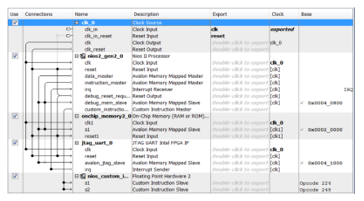 Figure 8: SOC system for software implementation
3.7. Comparison analysis of performance between hardware and software implementation MLP model
There are a few analysis done upon the completion of the FPGA model. The system reliability was relied on the output precision. The simulated output is compared with the real data to get the percentage error. Hence, the reliability of the proposed system can be evaluated. Equation (1) shows the calculation of percentage error:
![]() The system efficiency for both of hardware and software implementation was computed in MATLAB. After that, the expected output from both of the implementations were compared to inspect the system precision.
The system efficiency for both of hardware and software implementation was computed in MATLAB. After that, the expected output from both of the implementations were compared to inspect the system precision.
An additional analysis for determination of the reliability of the model was carried out using RMSE calculated from output data of the simulation. The purpose of the RMSE analysis on the model is to compare the regression between output from model in software implementation and hardware implementation of the MLP. By using this method, more accurate evaluation for the reliability of the system can be established. The formula of the RMSE is as equation (2):
![]() The execution time for both types of implementation were evaluated in ModelSim testbench interface to compare the performance. The execution time for hardware model was evaluated from the beginning of input signal to the MLP network up to the output signal at output layer meanwhile the software model was evaluated from the signal function to end of execution line in the instruction coding.
The execution time for both types of implementation were evaluated in ModelSim testbench interface to compare the performance. The execution time for hardware model was evaluated from the beginning of input signal to the MLP network up to the output signal at output layer meanwhile the software model was evaluated from the signal function to end of execution line in the instruction coding.
Table 1: Part of acquisition data
|
Distance (cm) |
Angle (o) |
X (pixel) | Y (pixel) | Width (pixel) | Height (pixel) |
|
20 |
-10 | 133 | 93 | 200 | 111 |
| 0 | 163 | 93 | 208 | 112 | |
| 10 | 193 | 92 | 202 | 111 | |
|
30 |
-10 | 126 | 94 | 144 | 81 |
| 0 | 161 | 94 | 151 | 82 | |
| 10 | 197 | 92 | 147 | 81 | |
|
40 |
-10 | 125 | 103 | 108 | 59 |
| 0 | 162 | 102 | 113 | 60 | |
| 10 | 200 | 100 | 109 | 59 | |
|
50 |
-10 | 123 | 103 | 88 | 47 |
| 0 | 161 | 102 | 91 | 48 | |
| 10 | 200 | 100 | 88 | 47 | |
|
60 |
-10 | 122 | 98 | 75 | 41 |
| 0 | 162 | 96 | 78 | 41 | |
| 10 | 202 | 95 | 76 | 40 |
4. Results and discussions
4.1. Data acquisition
The sets of data taken from Pixy CMUcam5 camera are distance, angle x-coordinate, y-coordinate, width and height. The area was internally calculated from width and height. Table 1 shows some parts of the acquisition data which are then used for further analysis in this research.
4.2. Weight and biases of MLP data training
Each neuron mapping produced single weight. As 10HNs present in the network, 10 weights generated and mapped to single output neuron. The total weights created were 20 since two output desired by the proposed design. Afterwards, two biases were created for each output neurons. Table 2 presents the generated weights and biases from the hidden to output layer of the network.
Table 2: Weights and biases generated from hidden to output layer
| Output of HN |
Distance weights |
Angle weights |
| 1st input | 0.3574 | 0.6727 |
| 2nd input | 1.1827 | 0.0759 |
| 3rd input | -0.3486 | 0.1218 |
| 4th input | -0.9544 | -0.2467 |
| 5th input | -0.6976 | -0.8491 |
| 6th input | -0.8869 | 0.3532 |
| 7th input | -0.5178 | 0.7513 |
| 8th input | 0.5719 | -0.3702 |
| 9th input | 0.5328 | -0.4183 |
| 10th input | 0.8046 | -0.0626 |
| Bias | 0.5993 | 0.2710 |
4.3. Simulation of MLP model
All output distance obtained from the MATLAB Simulink simulation showed no significant differences as the outputs resemble closely to each other with less than 3. By considering that the difference between the percentage error is low, practically it is absolutely normal and acceptable considering that the factors affecting the model in real world is taken into account in the simulation. Even though, an ideal case of equivalent percentage error for each data is impossible to be obtained as there will still be the linearity factor that affect the training process. Then, at three different angles of -10°, 0° and 10°, RMSE of 0.469, 0.479 and 0.267 respectively were successfully obtained. Similar to the case of non-equivalent percentage error produced, it is probably caused by linearity factor during raw data training where the training software is not linear and consistent. During initial training of raw data, random numbers are assigned as weight and bias to each neuron. Each cycle of repetitive training will constantly update these random numbers to predict the closest targeted output.
There are slight differences between calculated RMSE and percentage error for each output data due to short training time. The improvement could be made if the training is carried out rapidly on the data and will enhance the predicted output more accurately. Nevertheless, the percentage error and RMSE evaluation is only used as a reference to determine the reliability of the model developed. As stated in the scope, ANN and data training is only used as a tool to implementing the operating system of Cart Follower using the FPGA. As the training is done using MATLAB software, a Simulink simulation was performed to examine the reliability of the model before implementing it into the FPGA. Therefore, the percentage error from Table 3 as well as the RMSE calculated are used only as a reference where they have successfully proved that the model developed is fully functional and reliable. The actual distance was the directly measured distance meanwhile simulated distance was obtained by ANN computations.
Table 3: Data from MLP model for angle -10o, 0o, 10o
| Angle (o) | Actual distance (cm) | Simulated distance (cm) | Percentage error (%) | RMSE |
|
-10 |
20 | 19.48 | 2.65 |
0.469 |
| 30 | 29.53 | 1.57 | ||
| 40 | 39.98 | 0.05 | ||
| 50 | 49.95 | 0.12 | ||
| 60 | 59.24 | 1.28 | ||
|
0 |
20 | 19.76 | 1.20 |
0.479 |
| 30 | 29.16 | 2.80 | ||
| 40 | 40.04 | 0.10 | ||
| 50 | 50.18 | 0.36 | ||
| 60 | 60.59 | 0.98 | ||
|
10 |
20 | 19.86 | 0.75 |
0.267 |
| 30 | 30.02 | 0.07 | ||
| 40 | 40.37 | 0.92 | ||
| 50 | 49.72 | 0.70 | ||
| 60 | 60.27 | 0.45 |
4.4. Hardware implementation of ANN in FPGA
The execution time of hardware implemented model running at 1.91μs outperform the software implemented model. The reason behind was hardware implemented model is running in parallel meanwhile the software implemented model that is running in series. Figure 9 shows MLP hardware implemented model simulated in the ModelSim testbench.
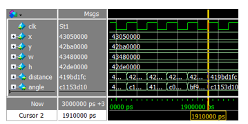 Figure 9: Hardware implemented model simulated using SOC system FPGA
4.5. Software implementation of ANN in FPGA
As the program code stops at address 20080h in the on-chip memory, the time is calculated from the start exert of reset bit to the address where the program code ends. Cursor 2 indicates the time reset start to exert while cursor 1 shows the time at address 20080h of the memory. Execution time is calculated from start of reset bit to the address 20080h where the code ends. The performance showed that it operated at 79.048532μs. Figure 10 shows the result of the software implemented model simulated using SOC system FPGA.
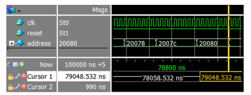 Figure 10: Software implemented model simulated using SOC system FPGA
4.6. Comparison analysis of performance between hardware and software implementation MLP model
The RMSE value for hardware and software implemented model are same at angle -10°, 0° and 10° as shown in Table 4. Past researchers presented with the deficiency of hardware implemented model precision since the floating point implementation was complex. A sign number is introduced to counter this problems. The usage of floating point can give an impact in increasing the efficiency of ANN MLP algorithm. As the hardware implemented model included the IP block floating point, the precision of the hardware can be said as same as software in terms of tracking performance of ANN with CC.
The execution time of hardware implemented model is at 1.91μs meanwhile software implemented model is at 78.06μs. This shows that performance of hardware is better than the software implemented. The reason behind was the software implemented model is running in sequential meanwhile hardware implemented model running in parallel. The software implemented model itself can only run in sequentially due to fetching of C code program that only has single lane to process data. It can be run in parallel but with aid of hardware implemented model. Table 4 presents the comparison between the hardware and software MLP model.
Table 4: Comparison between hardware and software MLP model
| Implementation | Hardware | Software |
| RMSE at angle -10o | 0.469 | 0.469 |
| RMSE at angle 0o | 0.479 | 0.479 |
| RMSE at angle 10o | 0.267 | 0.267 |
| Execution time (µs) | 1.91 | 79.05 |
5. Conclusions
In a nutshell, the objectives set for this research met the target. The hardware and software implementation in FPGA was performed with Verilog HDL. Floating point method was used in dealing with arithmetic calculation. The RMSE values for each angle of -10°, 0° and 10° show that the hardware implemented model was able to track the CC at high precision as software implemented model. The output distance produced from both of implementation appeared to possess an equal percentage error. Besides that, both the hardware and software implemented models at angles -10°, 0° and 10° also showed similar RMSE which are 0.469, 0.479 and 0.267 respectively. It has been proved that hardware implemented model is reliable as the software implemented model in term of target accuracy. This suited the first objective expectations.
The evaluation of execution time performance of both models show that hardware implementation model performed better than software implementation. The hardware and software implemented model operated at an execution time of 1.91μs and 79.05μs respectively. It is proven that model runs in parallel exhibited better performance than sequential. Therefore, the second objective is achieved.
The future development of this project can be enhanced by online training in FPGA. The application of this project can be applied to outdoor environment for various usage. The tracking system can be further developed with various AI systems like genetic algorithm, fuzzy or differential evolution for obtaining more comparison of FPGA controlled cart systems.
Conflict of Interest
The authors declare no conflict of interest.
Acknowledgement
The authors would like to thank Universiti Sains Malaysia (USM) for the support of the research under grant no 305/PELECT/6013112.
- G.A. Bekey, “Autonomous Robots: From Biological Inspiration to Implementation and Control”, MIT Press, 2005.
- T. Lozano-Perez, “Autonomous Robot Vehicles”, Springer Science & Business Media, pp. 462, 2012.
- T. Bräunl, 2008. “Embedded robotics: Mobile robot design and applications with embedded systems”, Springer Science & Business Media, pp. 434, 2013.
- G. Taylor and L. Kleeman, “Visual Perception and Robotic Manipulation: 3D Object Recognition, Tracking and Hand-Eye Coordination”, vol. Springer Tracts in Advanced Robotics, Springer, pp.218, 2008.
- J.M. Zurada, “Introduction to artificial Neural System”, (Vol. 8). St. Paul: West publishing company, 1992.
- M. Frutos-Pascual and B. G. Zapirain, “Review of the Use of AI Techniques in Serious Games: Decision Making and Machine Learning,” IEEE Transactions on Computational Intelligence and AI in Games, 2015.
- N. J. Nilsson, “Principles of Artificial Intelligence”, Morgan Kaufmann, 2014.
- W. Burgard, A. Derr, D. Fox and A. Cremers, ” Integrating global position estimation and position tracking for mobile robots: The Dynamic Markov Localization approach,” In IEEE/RSJ International Conference, Victoria, BC, Canada, Vol. 2, pp. 730-735, 1998. https://doi.org/ 10.1109/IROS.1998.727279
- M. Ghandour, H. Liu, N. Stoll and K. Thurow, “Human Robot Interaction for Hybrid Collision Avoidance System for Indoor Mobile Robots” Advances in Science, Technology and Engineering Systems (ASTES) Journal Vol. 2, No. 3, 650-657, 2017.
- M.F. Ahmad, S.S.N. Alhady, S. Kaharuddin and W.A.F.W. Othman, “Visual based sensor cart follower for wheelchair by using microcontroller”. In 5th International Conference on Control System, Computing and Engineering (ICCSCE), pp. 123-128. IEEE International Conference, Penang, Malaysia 2015. https://doi.org/10.1109/ICCSCE.2015.7482170
- M.F. Ahmad, H.J. Rong, S.S.N. Alhady, W. Rahiman and W.A.F.W. Othman, “Colour tracking technique by using Pixy CMUcam5 for wheelchair luggage follower”. In 7th International Conference on Control System, Computing and Engineering (ICCSCE), pp. 187-192. IEEE International Conference, Penang 2017. https://doi.org/10.1109/ICCSCE.2017.8284402
- M.F. Ahmad, S.S.N. Alhady, W. Rahiman, W.A.F.W. Othman and A.A.M. Zahir, “Visual Based Distance Recognition Technique by Using Pixy CMUcam5”. In Intelligent Manufacturing & Mechatronics: Proceedings of Symposium, Pekan, Pahang, Malaysia (pp. 479-485). Springer Singapore, 2018. https://doi.org/10.1007/978-981-10-8788-2_43
- M.F. Ahmad, S.S.N. Alhady, W. Rahiman, W.A.F.W. Othman and A.A.M. Zahir, “RGB Classification Determination with Different Light Intensity Using Pixy CMUcam5”. In Intelligent Manufacturing & Mechatronics: Proceedings of Symposium, Pekan, Pahang, Malaysia (pp. 517-525). Springer Singapore, 2018. https://doi.org/10.1007/978-981-10-8788-2_46
- C.M. Soria, R. Carelli, R. Kelly and J.M.I. Zannatha, “Coordinated control of mobile robots based on artificial vision”. International Journal of Computers Communications & Control, 1(2), pp.85-94, 2006. https://doi.org/10.15837/ijccc.2006.2.2288
- Z. Wang and M. Schwager, “Kinematic Multi-Robot Manipulation with no Communication Using force feedback,” In IEEE International Conference on Robotics and Automation (ICRA), Stockholm, Sweden, pp. 427-432, 2016.
- E. Prassler, D. Bank and B. Kluge. “Motion coordination between a human and a mobile robot” In IEEE/RSJ International Conference on Intelligent Robots and Systems (Vol. 2, pp. 1228-1233). IEEE, 2002. https://doi.org/10.1109/IRDS.2002.1043910
- T. Yoshimi, M. Nishiyama, T. Sonoura, H. Nakamoto, S. Tokura, H. Sato, F. Ozaki, N. Matsuhira and H. Mizoguchi, “Development of a Person Following Robot with Vision Based Target Detection,” In IEEE/RSJ International Conference on Intelligent Robots and Systems, Beijing, China, pp. 5286-5291, 2006. https://doi.org/10.1109/IROS.2006.282029
- M. Pakdaman and M.M. Sanaatiyan, “Design and Implementation of Line Follower Robot,” In Second International Conference on Computer and Electrical Engineering, Dubai, United Arab Emirates, Vol.2, pp. 585-590, 2009. https://doi.org/10.1109/ICCEE.2009.43
- R.C. Luo, C.H. Huang, T.T. Lin, “Human tracking and following using sound source localization for multisensor based mobile assistive companion robot,” In 36th Annual Conference on IEEE Industrial Electronics Society, Glendale, USA, pp. 1552-1557, 2010. https://doi.org/10.1109/IECON.2010.5675451
- S.O. Bamgbose, X. Li and L. Qian, “Trajectory Tracking Control Optimization with Neural Network for Autonomous Vehicles” Advances in Science, Technology and Engineering Systems (ASTES) Journal Vol. 4, No. 1, 217-224, 2019.
- M.L Chang, “Device architecture”. In Reconfigurable Computing, Morgan Kaufmann, pp 3-27, 2008. https://doi.org/10.1016/B978-012370522-8.50005-4
- R.D. Abdu-Aljabar, “Design and Implementation of Neural Network in FPGA”, In Journal of Engineering and Development, Vol. 16, No.3, pp. 73-90, 2012.
- P. Škoda, T. Lipić, Á. Srp, B.M. Rogina, K. Skala and F. Vajda, “Implementation framework for Artificial Neural Networks on FPGA,” In Proceedings of the 34th International Convention MIPRO, Opatija, pp. 274-278, 2011.
- L.Y. Tat, S.S.N. Alhady, W.A.F.W. Othman and W. Rahiman, “Investigation on MLP Artificial Neural Network Using FPGA for Autonomous Cart Follower System”, In 9th International Conference on Robotic, Vision, Signal Processing and Power Applications, Springer, Singapore, pp. 125-131, 2016. https://doi.org/10.1007/978-981-10-1721-6_14
- S. Agatonovic-Kustrin and R. Beresford,”Basic concepts of artificial neural network (ANN) modeling and its application in pharmaceutical research”, Journal of Pharmaceutical and Biomedical Analysis, Volume 22, Issue 5, Pages 717-727, 2000. https://doi.org/10.1016/S0731-7085(99)00272-1
- I.N. Da-Silva, D.H. Spatti, R.A. Flauzino, L.H.B. Liboni, S.F. Dos Reis Alves, “Artificial Neural Network”, Springer International Publishing, Edition 1, pp.21-24, 2017.
- R. Manickam, “Back Propagation Neural Network for Prediction of Some Shell Moulding Parameters”, Periodica Polytechnica, Mechanical Engineering, 60(4), pp. 203-208, 2016. https://doi.org/10.3311/PPme.8684
- F.W. Wibowo, “An Analysis of FPGA Hardware Platform Based Artificial Neural Network”, In Journal of Physics: Conference Series, Vol. 1201, No. 1, pp. 1-9. IOP Publishing, 2019. https://doi.org/10.1088/1742-6596/1201/1/012009
- N.B. Gaikwad, V. Tiwari, A. Keskar and N.C. Shivaprakash, “Efficient FPGA Implementation of Multilayer Perceptron for Real-time Human Activity Classification”, In IEEE Access, 7, pp.26696-26706, 2019. https://doi.org/ 10.1109/ACCESS.2019.2900084
- X. Zeng, Z. Li, J. Wan, J. Zhang, M. Ren, W. Gao, Z. Li and B. Zhang, “Embedded Hardware Artificial Neural Network Control for Global and Real-time Imbalance Current Suppression of Parallel Connected IGBTs.” In IEEE Transactions on Industrial Electronics, 2019. https://doi.org/ 10.1109/TIE.2019.2905825
- T. Jia, T. Guo, X. Wang, D. Zhao, C. Wang, Z. Zhang, S. Lei, W. Liu, H. Liu and X. Li, “Mixed Natural Gas Online Recognition Device Based on a Neural Network Algorithm Implemented by an FPGA”, Sensors, 19(9), pp.2090. https://doi.org/10.3390/s19092090
- J. Renteria-Cedano, J. Rivera, F. Sandoval-Ibarra, S. Ortega-Cisneros and R. Loo-Yau, “SoC Design Based on a FPGA for a Configurable Neural Network Trained by Means of an EKF”. Electronics, 8(7), pp.761. https://doi.org/10.3390/electronics8070761