
Optimized Design of PM Halbach Array Linear Generator for Sea Wave Energy Converters Operate at Maximum Power Transfer
Volume 4, Issue 4, Page No 440-448, 2019
Author’s Name: Ahmed Elsayed ELGebalya), Mohamed Kamal El-Nemr
View Affiliations
Electrical power and machines department Faculty of engineering, Tanta university, Tanta, 31527, Egypt
a)Author to whom correspondence should be addressed. E-mail: ahmed.elgebaly@f-eng.tanta.edu.eg
Adv. Sci. Technol. Eng. Syst. J. 4(4), 440-448 (2019); ![]() DOI: 10.25046/aj040453
DOI: 10.25046/aj040453
Keywords: Marine Renewable Energy Halbach Array, Linear Generators, Finite Element Method, Maximum Power Transfer

Export Citations
This paper proposes Halbach array PM linear generators for direct conversion of ocean or sea wave energy. This generator is proposed to be directly coupled to a reciprocating wave energy system which may be a valued alternative for pneumatic and hydraulic systems. In this research, air-cored permanent magnet PM linear generator has been optimally designed according to optimal cost and performance indices. The design depends on Halbach array PM arrangement. The design this linear generator is appropriate for direct extraction of energy from sea waves specially at small wave amplitude. The finite element method and the space harmonic analysis are used to develop the electromagnetic design of this topology. In this article, the concept of the extraction of maximum permissible power from sea waves is established according to the direct wave energy converters hydrodynamics model. The dynamic analysis of the Halbach array linear generator is investigated during the state of maximum power extraction.
Received: 31 May 2019, Accepted: 04 August 2019, Published Online: 16 August 2019
1. Introduction
This paper is an extension of work originally presented in 2018 Twentieth International Middle East Power Systems Conference (MEPCON) under title (Optimal Design of Slotless PM Halbach Array Linear Generator for Wave Energy Converters at Maximum Power Transfer Condition) [1]. Nowadays, the energy sources have great importance allover the world. Because of the expected deterioration of fossil fuels accompanied with hazardous environmental impacts, it is indispensable to establish clean renewable sources of energy. Ocean and sea waves energies are considered promising alternative renewable energies resources. On the Earth, it is considered as the largest renewable energy source. The running cost of this type of energy is low. Moreover, it is clean energy source. However, is not competently employed up till now. Preliminary reviews show that marine power has the ability to significantly contribute in energy market all over the world. Experts expect that the economical visibility of ocean or sea energies is very effective. It is expected that if wave-capturing technologies become totally developed, the predicted developed wave energy may equal 750 Trillion kWh/year [2].
Recently, numerous technologies are established to extract electric energy from seas or oceans waves [3]. These technologies are called the wave energy converters (WECs). They can transfer the mechanical wave energy to electrical energy. Such types of converters utilize the concept of a water column changing or buoy body movement [4]. Some of developed converters are more and more commercially established. There are some WECs directly convert the oscillating wave motion to reciprocal vertical movement. The small reciprocating motion with a speed about 2m/s may be obtained by these devices in some seas such as Mitterrandian Sea. Some researchers suggest the usage of induction generators to produce electric energy from sea waves. Nevertheless, this technology requires a hydraulic transmission system to convert the small velocity of the vertical motion to high rotational speed[5]. The wave energy converters which depend on the direct conversion of wave energy have great advantage related to the simple construction free of mechanical transmission system. The linear permanent magnet synchronous generators LPMSG have been developed and implemented as WECs which depend on the principle of Archimedes wave swing [1, 6]. The main shortage of such linear synchronous generators is the high cogging force. On the other hand, the air-cored tubular permanent magnet linear generators are suggested to overcome such force [7]. Therefore, the elimination of cogging force reduces the stress on the machine parts so there is no need for additional structure support. These machines can be built without the usage of back-iron. Therefore, the elimination of back-iron from stator and forcer leads to the elimination of their corresponding core loss. Additionally,
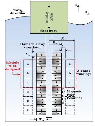 Figure 1: Proposed tubular Halbach array slotless linear generator for wave energy conversion
such generators have significant lightweight compared with the conventional linear synchronous generators. The improvement of flux distribution in the air-cored PM generators improve their performance from the point of view of the developed voltage and power [1]. Halbach array arrangement is applied to provide low space harmonics magnetic field, which leads to further sinusoidal waveform of induced voltage and more developed power with the same forcer current. The field uniformity leads to extracting of higher power over small time. Therefore, the Halbach arrangement is proposed to be implemented in these generators to gain its performance improvements [1, 2, 8].
The optimized design of the proposed PM Halbach array linear generators requires the fulfilment of some indices; such as cost minimization and the production of appropriate voltage and power level. The recent optimization techniques are applied to obtain the optimal design of generator which is suitable for wave energy extraction [9]. In this paper, the design details are taken into consideration to obtain the optimal design. The design variables include the generator topology, the appropriate PM arrangement, the coils design and the generator overall dimensions. Moreover, this research proposes the concept of maximum power tracking MPT to make use of the most delivered wave energy. Preliminary, the MPT concept is explained in this paper according to the hydrodynamic performance of the WEC. The application of MPT mode requires the implementation specific control technique and power electronics converter [10].
2. Modelling of hydrodynamics of direct WEC
Figure1 demonstrates the structure of air-cored tubular PM linear synchronous generator for WEC based Halbach array configuration. According to this design, the floating buoy is directly connected to the movable translator of the PM linear generator where its base is strongly fixed to the sea bottom. The generator base may be connected to the sea bottom via wires. The changing of the height of the wave is the base of the operation of the WEC. The hydrodynamic model of the direct buoy WEC has been developed previously in numerous researches [5, 11]. The difference forces act on the moving part of the translator have been modeled. Without reaction force control, the moving part are affected by three forces; the input force produced by the wave, the extracted output power and the inertia force. It is recommended to integrate a suitable mechanical spring in the WEC to develop reaction force counteracts the force of inertia developed by the movable parts. The maximum power transfer condition in the WEC systems happens when both the inertia and the spring forces are equal in value and opposite in direction [1, 2].
The buoy may take a cylindrical shape with radius r and its motion is limited to be along the vertical axis (z). The cylinder is partly immersed. When the wave acts on the buoy in x direction as illustrated in Figure (1), a force is applied on the buoy cylinder due its tendency for floating. In this study, the incident wave is considered to have sinusoidal wave for simplicity.
The buoy motion equation can be formulated as the following:
![]() where m is movable parts mass i.e. buoy and Halbach array PMs. Fstf is the force produced by the spring, Fgen is the reacting generator force due to electrical power extraction, and Fhyd are hydrodynamic forces applied on the buoy exerted by the wave.
where m is movable parts mass i.e. buoy and Halbach array PMs. Fstf is the force produced by the spring, Fgen is the reacting generator force due to electrical power extraction, and Fhyd are hydrodynamic forces applied on the buoy exerted by the wave.
The stiffness or spring force is proportional to the translator displacement,
![]() where kst is the constant of spring and z is the displacement on the vertical axis away from the balance point.
where kst is the constant of spring and z is the displacement on the vertical axis away from the balance point.
The force that causes the electrical power is modeled as a damping force where the produced force is proportional to the movable parts velocity. Therefore, the generated force is determined as:
![]() where B is the coefficient of damping which depends on the generated power. This coefficient should be continuously adjusted to enable the generator to extract the maximum allowable power from the wave.
where B is the coefficient of damping which depends on the generated power. This coefficient should be continuously adjusted to enable the generator to extract the maximum allowable power from the wave.
The Archimedes’ principle provides the equation that determine the hydrodynamic force correlated to the volume of water displaced:
![]() To study the hydrodynamic model in steady state mode, all equation should be transfer to the frequency domain by applying Fourier transformation. At steady state, the cylinder is assumed to be exposed to sustained alternating force has a frequency ω. The output power from the generator can be maximized when the system is in the resonance where the stiffness force equals in magnitude the inertia force. Therefore, the natural frequency ωr of the hydrodynamic system can be determined by [11]:
To study the hydrodynamic model in steady state mode, all equation should be transfer to the frequency domain by applying Fourier transformation. At steady state, the cylinder is assumed to be exposed to sustained alternating force has a frequency ω. The output power from the generator can be maximized when the system is in the resonance where the stiffness force equals in magnitude the inertia force. Therefore, the natural frequency ωr of the hydrodynamic system can be determined by [11]:
![]()
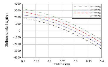 Figure 2: Variation of required stiffness constant with radius at different masses at ωr = 3 rad/s
The design of buoy cylinder relies on the hydrodynamic parameters which achieve the maximum power transfer condition. In this research, the proposed design is suitable for south shores of the Mediterranean Sea where the frequencies of the waves are within 3 radian per second [12]. The spring constant is determined depending on WEC rating and generator parameters [11]. Figure 2 illustrate the relation between the radius of buoy cylinder and the proper stiffness constant at different masses of movable parts. The required stiffness constant decreases with the increment of the radius. If the stiffness constant has negative values, the mass of the translator should be increased to achieve resonance condition [13]. So, the adjustment of spring constant is very vital to achieve the resonance condition; and therefore, to achieve the maximum power transfer condition. Nevertheless, the frequency of incident sea waves is continuously changed; so, the stiffness constant should be changed to change the natural frequency of the system to produce the maximum permissible power. The active adjustment of the stiffness constant is very complicated if it is mechanically implemented. Therefore, in this research, a adaptive electric spring is implemented to regulate the stiffness constant to run in resonance manner for different frequencies of the incident wave. The stiffness force or reaction force [10] can be created electrically due to certain current and voltage adjusted by power electronics converters. In this article, reaction force is applied during the operation of the generator to produce maximum power. Nevertheless, the movable parts mass should to be minimalized to reduce the reaction force and consequently, the produced generator current and its corresponding losses. Therefore, the mass of the generator movable parts is a vital index to obtain the optimized design.
3. Design of Halbach array WEC generator using FEM
Figure 1 illustrates that the proposed PM Halbach array linear generator has fixed coils surround a PM tubular Halbach array. The translator is composed of directed polarized permanent magnets for instance NdFeB. The magnets fluxes are directed with special sequence North (N) and South (S). But, the complete of the magnetic flux requires some magnets to be oriented in (C) direction. The PMs labeled (U) are oriented with 45 degrees or 135 degrees to produce smooth sinusoidal distributed flux. The resultant field tracks the translator motion, passing through the the concentrated coils. This paper studies the design of one module and the other modules have the same design parameters.
Low velocities WECs requires large reactive forces, therefore large dimension generators. In such iron-cored generators, the robust magnetic field leads to a noteworthy attraction force between the movable part and stator [14]. The structure can be significantly saved in the case when the cogging force can be decreased or even cancelled. The slotless air-cored linear generator is considered as a solution. The Halbach array has a vital advantage over the traditional air-cored related to the production of magnetic flux with less space harmonic content. The proposed generator module has the next ratings: 600 w rated power, 60 V rated phase voltage, the height of the wave about 1 m and the frequency of the wave about 3 rad/s. The ratings of the generator and wave is suitable to be applied on South Mediterranean Sea [12].
The proposed module may be repeated vertically to absorb larger amount of power from the incident wave. The overall length of generator depends on the depth of sea in the place of installation and on the stresses applied on the construction of the generator. In this research, the proposed generator has 3 kW; so, it consists of five modules. The following procedures explains the steps to obtain the optimal design of one module.
The investigation of the proposed model has been achieved by the application of finite element method by using FEMM package. Due to the slow motion of the translator in such type of generators, the analysis of the generator is considered magnetostatic problem. The problem of electromagnetic field is analyzed depending on FEM. The following equations is solved by FEM to analyze any electromagnetic problem. The vector of magnetic potential A is related to the vector of current density J by the following equation:
![]() where, (μ) is the permeability that depends the flux density for nonlinear materials. The advantage of solving FEM problem depending on the vector potential A is that all circumstances to be fulfilled are integrated within on equation. If A is determined for any geometry, the corresponding density of magnetic flux can be determined according:
where, (μ) is the permeability that depends the flux density for nonlinear materials. The advantage of solving FEM problem depending on the vector potential A is that all circumstances to be fulfilled are integrated within on equation. If A is determined for any geometry, the corresponding density of magnetic flux can be determined according:
![]() The proposed designs of the generators are analyzed by FEM to achieve the required ratings. Figure 1 illustrates the various dimensions of the module; Ro the outer radius of the module, τ is the pole pitch, Lg is air gap length, Lm is PM segment height, Wm is PM thickness and Rm is the PMs cylinder outer diameter.
The proposed designs of the generators are analyzed by FEM to achieve the required ratings. Figure 1 illustrates the various dimensions of the module; Ro the outer radius of the module, τ is the pole pitch, Lg is air gap length, Lm is PM segment height, Wm is PM thickness and Rm is the PMs cylinder outer diameter.
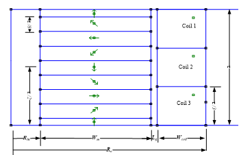 Figure 3: Full dimensions of one module of the proposed generator design
There are additional generator design parameters foi instance number of windings of each coil, the cross-section area of the copper conductors and the coil’s filling factor. FEM analysis helps to determine the parameters of the design which achieve the suitable ratings. For any proposed dimensions and materials, FEM can calculate the different variables of the generator such as flux linkage, developed force overall weight. For each determined variable, the objective function is formulated to obtain the optimized design. Figure 3 illustrate the full dimensions applied in FEM for axisymmetric representation while Rin is the PMs cylinder inner radius, Wcoil is the coil width and τ is the pole pitch. Along one pole pitch, the PM cylinder is divided into eight species. Along the full length of the translator, there are number of pole pitches equals Npit. Over each pole pitch, the stator contains three coils where each coil presents one phase. The modularity of the proposed design allows to provide different generator ratings. Consequently, in case of 600 W module, generators of 1200, 1800 and 2400 W are developed. The control system applied for one module can be applied for the other modules without modifications.
Because of tubular shape of generator, the simulated model in FEMM is presented in axisymmetric dimensions. Several efforts have been achieved in [1], [2] and [5] which present a good guide to determine the probable ranges of design variables appropriate for the predetermined ratings demonstrated in Table.1.
The package FEMM is used to implement the finite element analysis of the proposed generator. The slow motion of the translator and the currents low frequencies which passes through coils lead to solving of the finite element problem as magnetostatic problem.
The optimization problem has some constrains; the first constrain is the filling factor of each coil should be less than 85 %; the second constrain is the losses which shouldn’t exceed 50 % of the developed power. The dissipation of generator losses under water governs the description of constrains [2].
Some of post-process results of FEM present important terms which formulate the objective function. The obtained parametes are are as the following, the volume of PM segment Volpm, the volume of the coil Volcoil, the produced loading force Fd, copper losses Pcu, and the maximum flux linkage at no-load λmax. Some post-process results are essential to obtain some fitness function terms. The mass of both PMs and coils should be determined as the following:
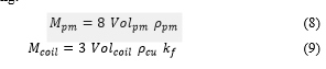 where Mpm is the mass PM cylinder for one module, ρpm is the PM material density, Mcoil is the three-phase coils mass, ρcu is the density of copper and kf is the filling factor. The maximum flux linkage per pole pitch λmax/τ is an essential parameter should to be calculated to formulate the objective function.
The objective function is formulated to obtain the optimized design according to the next indices:
1- minimization of coils’ mass
2- minimization of PM translator mass
3- achieving the rated power
4- achieving the rated voltage
Consequently, the objective function is formulated as the following:
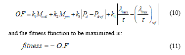 where Pd is the produced power by certain model, Pdref and (λmax/τ)ref present the reference values and constants k1 to k4 are used as weighting factors to adjust the contribution of O.F. terms.
Figure 3 illustrates the FEM presentation of one module located at the balance position where z = 0. With minimum number of calculations, this position has advantage related to the determination of required values of maximum flux linkage at no-load for coil 2 and developed force at loading if both coil 1 and coil 3 have maximum current. the proposed arrangement provides the benefit of obtaining the terms of objective function deprived of carrying out a complex dynamic modeling using FEM.
|
Table 1: the probable ranges of design variables appropriate for the proposed Halbach array generator
|
In this research, the Genetic Algorithm (GA) is applied to obtain the optimized design with minimum weight and losses and provides voltage and power ratings.
Figure 4 demonstrates the flux produced by the Halbach array where the flux is directed out of the side area of the cylinder and partly deleted in the inner side of the cylinder. For the same generators volume, the characteristics related to providing higher power density of Halbach array linear generator is better than these of air-cored generator [2].
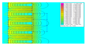 Figure 4: The Halbach array produced magnetic flux distribution and contour
To obtain the optimal values for the parameters, GA is applied to maximize the fitness function. In this study, the generation consists of 20 gene is applied. The six parameters are coded within one gene as binary string where these parameters are illustrated in Table.1. Therefore, the gene is composed of 120 bit. Then, the design parameters are passes to FEMM package to obtain their indices and design results. Then, the post-processing parameters are calculated. Therefore, the objective function and fitness value is determined for each gene. Then, GA applies its reproduction processes. The developed programs are carried out using programming language C++ and MFC library.
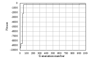 Figure 5: Fitness variation with GA generations for the optimization problem
The process of search is completed if the fitness value is stable at almost fixed value. Figure 5 demonstrates the changing of the fitness value versus the number of generation. After 1000 generation, the maximum fitness is stabilized at -270 as best vakue as shown in Figure 5. The stabilized fitness value is achieved approximately after 120 generations.
Table 2 illustrates the details of optimized design of the proposed generator topology for the specified ratings. The developed parameters of the optimized design are used in the dynamic analysis of the generator when it works in maximum power transfer state. The power density of the optimized design equals 41.6 W/kg which is more than the conventional air cored by 10% which equals 38 W/kg [15].
|
Table 2: The detailed parameters and dimensions of the optimized design
|
|||||||||||||||||||||||||||||||||||||||||||||||||||||||||
4. Performance assessment of Halbach array linear generator of WEC at maximum power transfer
According to the dimensions determined by the FEM, each coil of the there-phase has flux linkage over the displacement with one pole pitch illustrated in Figure 6. The flux linkage has sinusoidal waveform over τ.
Figure 7 demonstrations the equivalent circuit of the three-phase Halbach array linear generator. The there-phase equivalent circuit model consists of three EMF supplies ea, eb and ec. the phases assumed to be connected in star. Moreover, the model for each phase contains an internal winding resistance rin, self-inductances La and the mutual induced voltage due to currents pass in the other phases is presented by two dependent sources. The load
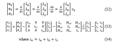
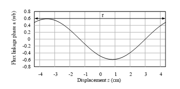 Figure 6: The changing of flux linkage with the vertical displacement over one pole pitch
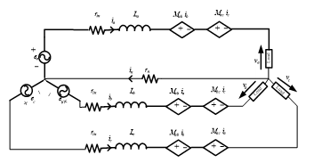 Figure 7: The equivalent circuit of the three-phase model of proposed Halbach array linear generator
To apply the maximum transfer condition from the mechanical point of view, the inertia force should be eliminated by stiffness force produced by applying current iq* has phase shift of 90̊ with the induced phase voltage envelop [1]. From electrical point of view, the maximum power transfer happens when the circuit current is in phase with applied voltage. So, there is another current id* is in phase with voltage and therefore with the velocity. In (12), the voltage mainly relies on flux linkage and the velocity of the PM cylinder regarding the three-phase coils. In this generator, the energy is extracted from both rising and falling motions.
Now, the proposed Halbach array generator module is tested under two cases; the first when the maximum wave velocity equals 1.5 m/s and the second when it equals 1 m/s. Figure 8(a) shows the velocity applied on the floating buoy of WEC where the maximum velocity equals 1.5 m/s. This velocity is supposed to have sinusoidal waveform while its positive value means that the direction is up towards and the negative value means the reverse direction. As shown in Figure 8(b), the span of displacement ranges from 50 to -50 cm. Figure 8(c) illustrates the changing of the coils flux linkage during translator movement. As shown in Figure 8(d), the three phase voltages have 120° phase shift between each other although the voltages amplitude changes. Correspondingly, the velocity of the generator is directly related to the frequency of the induced voltages. The frequency related to speed should be considered during the voltage control of the generator output. The way of power extraction related to the value of currents passes through coils. Thus, the MPT is achieved by current regulation technique. Therefore, the MPT is achieved by allowing current iq to pass through coils to produce stiffness force cancels the inertia force. Figure 8(e) illustrates the current iq where its envelop has 90° phase shift with the envelop of voltage. Therefore, current iq envelop is in phase with the translator displacement according to equation (2). The production of active power is achieved by allowing current id to pass through generator phases. The envelop of current id is in phase with the envelop of induced voltage as in Figure 8(e). Therefore, the maximum power transfer is achieved by allowing total current itot to be pass through each phase; where
![]() These currents for phase a are illustrated in Figure 8(f). The total current with its two components can cancel mechanical inertia and electrical inductances. Figure 8(g) demonstrates both the stiffness and inertia powers which have the same amplitude and opposite sign. Figure 8(h) demonstrates the total output power Ptot produced by the generator at MPP and the output power Pout.
These currents for phase a are illustrated in Figure 8(f). The total current with its two components can cancel mechanical inertia and electrical inductances. Figure 8(g) demonstrates both the stiffness and inertia powers which have the same amplitude and opposite sign. Figure 8(h) demonstrates the total output power Ptot produced by the generator at MPP and the output power Pout.
Figure 9 illustrates the generator performance at 1 m/s maximum velocity. It can be observed that the span of movement is reduced by 36 cm. Although the flux linkage, in this case, has the same amplitude, the induced phase voltages have less amplitude because they depend on the velocity. The currents are reduced due to the reduction of reaction forces and the total and output power. According to the results at different velocity, the concept of operation of MPT can applied to obtain the maximum power from the waves.
5. Conclusion
Slotless tubular Halbach array linear generator has been developed to be used within wave energy converter system at maximum power transfer condition. The simple hydrodynamic model of the WEC have been developed to describe the hydrodynamic circumstances to achieve MPT condition. The principle of operation of the proposed Halbach array linear generator has been introduced. Moreover, the parameters affects the design of the generator have been derived to formulate the proper objective function. The FEM has been used to get the design parameters for different dimensions of the generator. The GA in combined with FEM is used to get the optimal parameters of generator design achieves the maximum fitness value. The optimized design has been modeled and simulated to study its performance in the maximum power transfer condition. The WEC system has been simulated to work with low velocity sea waves as these in the Mediterranean Sea. The MPT has been successfully achieved by using the concept of current control to cancel all system inertias.
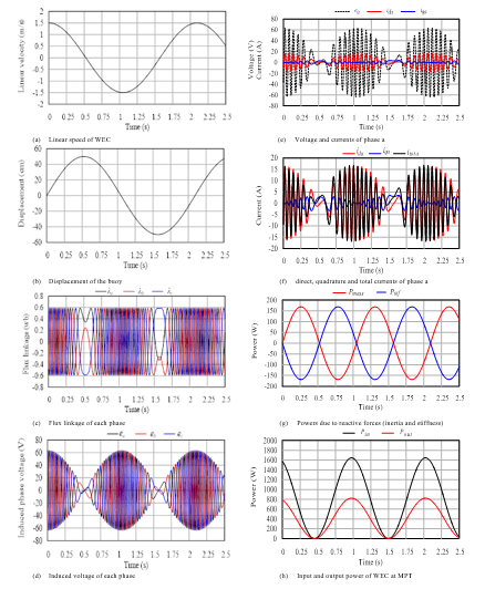 Figure 8: The performance of Halbach array linear generator as WEC at maximum linear speed with 1.5 m/s
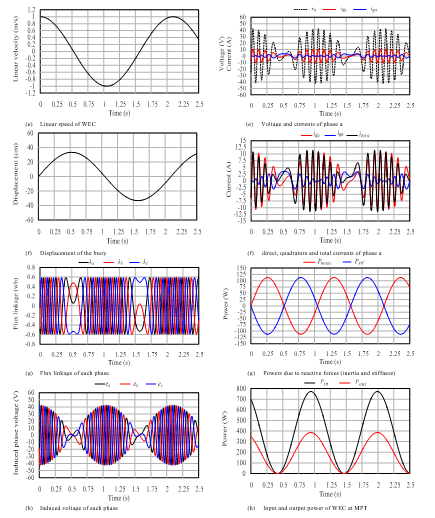 Figure 9: The performance of Halbach array linear generator as WEC at maximum linear speed with 1 m/s
Acknowledgment
This study is performed at Energy Conversion Research Laboratory, Electrical power and Machines Department, Faculty of Engineering, Tanta University, Tanta, Egypt
- Ahmed E. ELGebaly, Mohamed K. El-Nemr, “Optimal Design of Slotless PM Halbach Array Linear Generator for Wave Energy Converters at Maximum Power Transfer Condition”. in 2018 20th International Middle East Power Systems Conference, MEPCON 2018, Cairo, Egypt, 2018. https://doi.org/10.1109/MEPCON.2018.8635113
- Ahmed E. ELGebaly, Mohamed K. El-Nemr, “Design and performance evaluation of halbach array linear generator for wave energy converters”. in 2015 IEEE 8th GCC Conference and Exhibition, GCCCE 2015. Muscat, Oman, 2015. https://doi.org/10.1109/IEEEGCC.2015.7060035
- M. Mueller and H. Polinder, “Electrical Drives for Direct Drive Renewable Energy Systems. Electrical Drives for Direct Drive Renewable Energy Systems” 1–264 (Elsevier Ltd, 2013). doi:10.1533/9780857097491
- Bedard, R., Jacobson, P., Previsic, M., Musial, W. & Varley, R. An Overview of Ocean Renewable Energy Technologies. Oceanography 23, 22–31 (2011). doi: 10.5670/oceanog.2010.40.
- Vining, Jennifer, Tim Mundon, and Balky Nair. “Electromechanical Design and Experimental Evaluation of a Double-Sided, Dual Airgap Linear Vernier Generator for Wave Energy Conversion.” 2017 IEEE Energy Conversion Congress and Exposition, ECCE 2017. doi: 10.1109/ECCE.2017.8096926
- H. Polinder, B. C. Mecrow, A. G. Jack, P. G. Dickinson, and M. A. Mueller. “Conventional and TFPM Linear Generators for Direct-Drive Wave Energy Conversion” IEEE TRANSACTIONS ON E NERGY CONVERSION, VOL. 20, NO. 2, JUNE 2005
- Salauddin, M., M. A. Halim, and J. Y. Park. “A Low Frequency Vibration Energy Harvester Using Dual Halbach Array Suspended in Magnetic Springs.” Journal of Physics: Conference Series. Vol. 660. Institute of Physics Publishing, 2015. doi: 10.1088/1742-6596/660/1/012011
- Zhu, Z.Q., and D. Howe. “Halbach Permanent Magnet Machines and Applications: A Review.” IEE Proceedings – Electric Power Applications 148.4 (2002) doi: 10.1049/ip-epa:20010479
- Hodgins, Neil et al. “Design and Testing of a Linear Generator for Wave-Energy Applications.” IEEE Transactions on Industrial Electronics 59.5 (2012): 2094–2103. IEEE Transactions on Industrial Electronics doi: 10.1109/TIE.2011.2141103
- B. Guo, R. Patton, M. Abdelrahman and J. Lan. “ A continuous control approach to point absorber wave energy conversion 2016 UKACC 11th International Conference on Control (CONTROL), 31 Aug.-2 Sept. 2016, Belfast, UK. doi: 10.1109/CONTROL.2016.7737655
- Zheng, Xiong Bo, Jin Jiang, and Liang Zhang. “Power Characteristic Analysis and Optimization of Point Absorber Wave Energy Converter.” Applied Mechanics and Materials 313–314 (2013): 837–842. https://dx.doi.org/10.4028/www.scientific.net/amm.313-314.837
- Kaiser, M. F.M., and O. E. Frihy. “Validity of the Equilibrium Beach Profiles: Nile Delta Coastal Zone, Egypt.” Geomorphology 107.1–2 (2009): 25–31. doi: 10.1016/j.geomorph.2006.09.025
- Hazra, Samir et al. “Dynamic Emulation of Oscillating Wave Energy Converter.” 2014 IEEE Energy Conversion Congress and Exposition, ECCE 2014. Institute of Electrical and Electronics Engineers Inc., 2014. 1860–1865. 2014 IEEE Energy Conversion Congress and Exposition, ECCE 2014. doi: 10.1109/ECCE.2014.6953645
- Dawande, M. S., Kanetkar, V. R. and Dubey, G. K. “Three-phase switch mode rectifier with hysteresis current control”. IEEE Transactions on Power Electronics 11, 466–471 (1996). https://doi.org/10.1109/63.491640
- Farrok, Omar et al. “A New Optimization Methodology of the Linear Generator for Wave Energy Conversion Systems.” Proceedings of the IEEE International Conference on Industrial Technology. Vol. 2016-May. DOI: 10.1109/ICIT.2016.7474965