
A Balanced RF Power Amplifier using the Improvement 3-dB Quadrature Hybrid Couplers for Mitigation of the Reverse Intermodulation in FM Broadcasting Systems
Volume 4, Issue 4, Page No 421-430, 2019
Author’s Name: Panya Hantula, Rangsan Tongtaa)
View Affiliations
School of Telecommunication Engineering, Institute of Engineering, Suranaree University of Technology, 111 University Avenue, Muang District, Nakhon Ratchasima, Thailand.
a)Author to whom correspondence should be addressed. E-mail: tongta@sut.ac.th
Adv. Sci. Technol. Eng. Syst. J. 4(4), 421-430 (2019); ![]() DOI: 10.25046/aj040451
DOI: 10.25046/aj040451
Keywords: Reverse Intermodulation, FM Power Amplifiers, Balanced RF Power Amplifiers, 3-dB Quadrature Couplers, Broadside-coupler Striplines, Printed Circuit Broads (FR-4)

Export Citations
FM broadcast stations generate reverse intermodulation signals that cause communication problems between ATC controllers and pilots in the Air Traffic Control systems (ATC) in Thailand. In this paper proposes a balanced RF power amplifier using the improvement
3-dB quadrature hybrid couplers to reduce the reverse intermodulation of FM broadcasting systems. The mathematics analysis of the balanced RF power amplifier for two closely located FM stations shows that can reduce the reverse intermodulation products. A reverse signal from nearby FM stations travels into two amplifiers of a balanced amplifier that create intermodulation signals. The quadrature hybrid coupler in a balanced RF amplifier to provide intermodulation signals of two amplifiers have a 180? out-of-phase which cause reducing intermodulation signals. In this paper designs 3-dB quadrature hybrid couplers for a proposed RF balanced amplifier. The low-cost PCBs are used to make prototype couplers. The proposed couplers are provided experimental results of return losses that are lower than -15 dB. The directed port has a coupling coefficient -3.3 dB and the coupled port has a coupling coefficient -3.4 dB. The prototype couplers are applied to a balanced amplifier that obtains a maximum output power 210 watts with 17.20 dB gain. A proposed balanced RF amplifier is measured the reverse intermodulation products of with a situation of two closely located FM broadcast stations to compare with a single-stage class-C amplifier. The experimentation demonstrates of the transmitter using a balanced RF power amplifier that can reduce an intermodulation product 18.47 dBc.
Received: 31 May 2019, Accepted: 29 July 2019, Published Online: 16 August 2019
1. Introduction
The RF power amplifiers are important components for wireless communication systems. The design techniques for RF amplifier can use classes A, B, C, and AB, etc. Each type of class-amplifiers has different features and performances. The class-C amplifiers are suitable for FM broadcasting systems because it has the output power and efficiency higher than other types. The disadvantage of class-C power amplifiers is non-linearity which creates harmonic and intermodulation signals. Harmonic signals are multiple of the fundamental frequency. It can be eliminated by using the Low Pass Filters. Intermodulation signals are unwanted signals of non-linear RF power amplifiers. When the power amplifier of FM station is injected by two frequencies which are generated intermodulation signal to fall into the other frequency ranges. The intermodulation products can be calculated from
and [1].
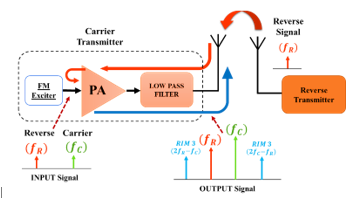 Figure 1: The reverse intermodulation products of FM broadcast stations
Although, the FM broadcast station uses an RF power amplifier with a single frequency. In practice, the signals from nearby FM broadcast stations can radiate to the own station. In Figure 1, two closely located FM broadcasting stations, the signal from a reverse transmitter radiates into a carrier transmitter via an antenna and transmission line in the reverse direction, called “Reverse Signal”. The reverse signal travels until it present at the input of a carrier transmitter. So, the station own signal and the reverse signal create intermodulation signals, called “Reverse Intermodulation (RIM)”.
The FM broadcast station uses a low pass filter in the final stage to block unwanted signals, such as harmonic and intermodulation signals. A low pass filter has a wide transition band, the frequency response to change from a pass-band to a stop-band. Which frequencies of intermodulation products are very close to a cut-off frequency point of the filter that cannot eliminate intermodulation products with a low pass filter. The FM broadcast station using the frequency band is 88-108 MHz that are close to the frequency band of Air Traffic Control (ATC) systems, using the frequencies between 108-137 MHz. Therefore, reverse intermodulation signals from FM station generates may be interferences communication between air traffic controllers and pilots, as shown in Figure 2. [2]
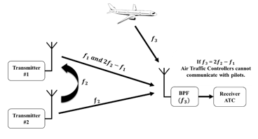 Figure 2: Intermodulation products interference to Air Traffic control systems
To overcome this problem, circulators or cavity bandpass filters are alternatives to reduce intermodulation products.
It can block reverse signals from nearby stations and unwanted signals from the own station. Disadvantages of circulators and cavity bandpass filters are adding considerable cost, complexity and power loss to a system. As will be shown, none of the techniques available to reduce reverse intermodulation are particularly attractive.
This paper presents a balanced RF power amplifier using the improvement 3-dB quadrature hybrid couplers to reduce reverse intermodulation signals of FM broadcast station. The concept of balanced RF power amplifiers is structured from two identical quadrature couplers and two signal-stage amplifiers. The reverse signal from nearby FM stations radiates to the own station until it present at the input of two signal-stage amplifiers that generated intermodulation signals. The second quadrature hybrid coupler provides a 180˚ out-of-phase of two intermodulation signals from two amplifiers that can cancel intermodulation signals. The mathematics analysis of a balanced RF power amplifier for two closely located FM stations shows that can reduce the reverse intermodulation products, will be explained in section 3. In the previous work presents a design and implementation of the prototype 3-dB quadrature couplers [3]. In this work, prototype
3-dB quadrature couplers are included in a structure of a balanced RF power amplifier to reduce reverse intermodulation signals of FM broadcast station.
The quadrature hybrid couplers are an important component for a balanced RF power amplifier. Due to it can separate an input signal into two identical amplifiers and combines both output signals. The quadrature hybrid coupler has a very beneficial feature that can reduce a reverse intermodulation signal of FM broadcasting systems. The branch-line hybrid couplers are applied to traditional couplers for the balanced rf power amplifier. The branch-line is a simple type of quadrature couplers that are realized by using four transmission lines to construct a single-box coupler [4]-[5]. Each line in the single-box is a quarter-wavelength transmission line. The disadvantage of branch-line couplers is a large physical size because a quarter-wavelength transmission line determines the physical size of branch-line couplers. Especially, FM broadcasting systems use a low-frequency range that is a long transmission line that increases physical size. The large physical size is unsuitable to use for an RF power amplifier of the FM stations [6]-[10]. The quadrature hybrid couplers in this paper are structured by using the broadside-coupler stripline technique to reduce the size of couplers. Section 4 describes the design, implementation of quadrature hybrid couplers.
The prototype quadrature couplers are applied to a balanced RF power amplifier. The two identical single-stage amplifiers use
a class-C RF amplifier with two MRF151 N-channel MOSFETs and operate at the frequency range of 88-108 MHz. Experimental results of the total output power, a frequency response of prototype balanced power amplifier will be presented in section 5. The situation of two closely located FM broadcast stations is used to create the reverse intermodulation signal. Two carrier transmitters that use a single-stage power amplifier and a balanced RF power amplifier have been measured. The FM broadcast station using
a balanced power amplifier eliminates the intermodulation signals by using the phase-shifting property of the quadrature hybrid coupler. The reverse signals from nearby FM stations and the intermodulation signals have a 180˚ out-of-phase which can be canceled the reverse signals and RIM signals without the cavity bandpass filters and circulators. Experimental results of the FM broadcast station using a balanced RF power amplifier comparing with single-stage RF power amplifier are presented in sections 6.
2. RF Power Amplifier for FM Broadcasting Systems
2.1. Class-C Power Amplifiers
The RF power amplifiers are an electronic circuit that transfers an input power to load such as the antenna by amplifying.
FM broadcasting systems require high output power and efficiency. The Class-C amplifier offers the highest efficiency more than Class-A, Class-B, and Class-AB. The efficiency of Class-C amplifiers can be approximated about 70-80%. The disadvantage of Class-C amplifiers is non-linearity which has poor distortion qualities and generates harmonics [11]. When two signals are the input of an amplifier that creates intermodulation components (IM). The several techniques are presented reducing the intermodulation distortion by improved the RF power amplifiers, such as the feed-forward techniques [12], etc. They are suitable to the multicarrier amplifiers which cannot eliminate the reverse signal from nearby FM broadcast stations.
2.2. Non-linear Distortion and Intermodulation Products
Non-linear distortions can be described in terms of a non-linear relationship between the input and output signals. The non-linearity creates several effects such as harmonic and intermodulation signals. Harmonic signals are unwanted signals which are included a number of integer multiples of an input frequency. Intermodulation signals occur when an input of
non-linear systems are composed of two frequencies. FM broadcast stations use a Class-C amplifier that is a nonlinear system. Therefore, we can express by:
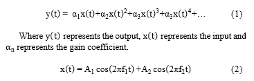
 If an input signal consists of two signals with different frequencies that are applied to a nonlinear system (1). The resultant of the output can be expressed as:
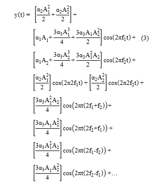
From (3), the output that does not contain only the fundamental frequency. The nonlinearity gives other frequencies adding to output components. The second term of this expression shows the amplitude of the fundamental frequencies. The third term shows the second-order harmonics. The fourth and fifth terms show third-order intermodulation distortions. The terms of , are third-order intermodulation products. The intermodulation signals are very close to fundamental frequencies which are cannot be easily filtered.
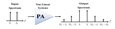 Figure 3: Intermodulation Products of nonlinear systems
3. Balanced RF Power Amplifier
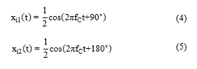
The balance RF power architecture shows in Figure 4. Two identical signal-stage amplifiers are parallel connecting with two quadrature hybrid couplers. Both amplifiers share the same input signal ( ) which is fed through the quadrature hybrid coupler. The first quadrature hybrid coupler on the input is the splitter that divides an input signal (from port 1) into two equal amplitude outputs (port 2 and port 3) with a 90˚ phase difference. The input signal of the first amplifier (PA1) has been 90˚ phase-shifted and the signal of the second amplifier (PA2) has been 180˚ phase shifted. Two amplifiers have the same bias voltage that provides equal output power capability. The second quadrature hybrid coupler on the output is a combiner that is connected to the output stages of two amplifiers. which an output signal of PA1 connect to port 1 and an output signal of PA2 connect to port 4. Both output signals are in-phase on port 3 that means output signals from two amplifiers are combined. While output signals are out-of-phase at port 2 that mean the output signals from two amplifiers are canceled. A port 2 of a hybrid coupler is an isolation port that is terminated by match load 50Ω.
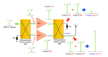 Figure 4: The balanced RF power amplifier structures
3.1. Analysis of the Balanced RF Power Amplifier to Reduce Reverse Intermodulation Products
 This paper proposes the balanced RF power amplifier that reduces the reverse intermodulation products. From Figure 5,
an input signal is which represents the FM modulation signal. The input signal is fed through the first quadrature hybrid coupler which separates an input signal into two equally signals with a 90˚ phase difference, we can express by:
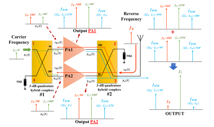 Figure 5: The analysis of a balanced RF power amplifier to reduce reverse intermodulation products
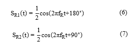 Where is an input signal for the first power amplifier and the is an input signal for the second power amplifier. The represent a carrier frequency. When the reverse signal ( ) from nearby FM station travels in a reverse direction until it presents at the output stage, the port 3 of a second quadrature hybrid coupler. A similar expression for the output stage of a balanced amplifier, a second quadrature hybrid coupler is the symmetric 4-port microwave device that separates a reverse signal to two equally signals with a relative phase difference of 90˚. We can express both reverse signals by:
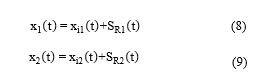
Where and are the respective reverse signals traveling into two power amplifiers and the is a frequency of
a reverse signal. Both reverse signals travel in the reverse direction through the coupler until they present at the input of each amplifier. Input signals ( ) together with the reverse signals ( ) present at an input of each power amplifiers, can be written as follows:
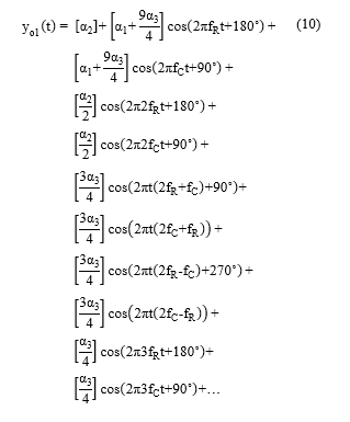 The and are the respective input signals of two power amplifiers. We use and to a nonlinearity equation of power amplifiers (1). Therefore, a resultant of the output can be expressed as:
The and are respective output signals of two power amplifiers. Both output signals are several effects of
a nonlinear distortion that contains the term of the carrier frequency, the reverse frequency, the harmonics, and the third-order intermodulation products. Both output signals are combined by a second quadrature coupler which is connected to an output signal at port 1 and an output signal at port 4. The term of a reverse frequency and the term of intermodulation product are out-of-phase on port 3 of a second quadrature coupler. Thus, the reverse signal and the intermodulation signal are canceled. A similar expression, a term of a carrier frequency is in-phase on port 3. So that the total output power can be increased and can be expressed as:
The math model of balanced RF power amplifiers with a carrier frequency 100 MHz and a reverse frequency
95 MHz is simulated. The line spectrums of simulation results show in Figure 6. The intermodulation signals in term of and a reverse signal are eliminated.
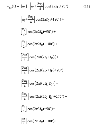
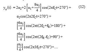
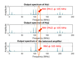 Figure 6: Simulation results of the math model based on a balanced RF power amplifier
3.2. Intermodulation Measurements
The third-order intermodulation distortion creates additional frequencies in terms of and . The measurement is described by the power ratio between the power level of a fundamental frequency and intermodulation products, can be expressed as:
![]() Where the is a power of a fundamental frequency and the is the power of a third-order intermodulation product. The is the intermodulation level (dBc) of an intermodulation product relative to a power level of the fundamental frequency.
Where the is a power of a fundamental frequency and the is the power of a third-order intermodulation product. The is the intermodulation level (dBc) of an intermodulation product relative to a power level of the fundamental frequency.
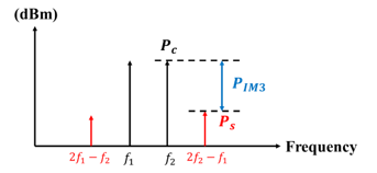 Figure 7: Intermodulation Distortion Measurement
4. Design and Implementation of 3-dB Quadrature Hybrid Couplers
The conventional couplers for balance power amplifiers use branch-line hybrid couplers because it is simple and easy to make. The size of the branch-line couplers is increased when using in an FM frequency range. The reducing of the physical size of branch-line couplers, many methods have been suggested. The slow-wave transmission line technique can make short-wavelength transmission lines by reducing phase velocity [13]-[17]. The increasing of inductances and capacitances with the same ratio causes reducing phase velocity while a characteristic impedance of the coupler is unchanged. Also, lumped-element hybrid couplers use for reducing the circuit size of branch-line hybrid couplers [18]-[19]. Lumped-element circuits are realized by using
LC-microstrip resonance circuits to replace the line sections of branch-line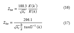
couplers. The lumped-element circuits have a characteristic impedance equivalent to the quarter-wavelength transmission line while the circuit size of lumped-element circuits is shorter than the branch-line couplers.
Lange couplers are two parallel microstrip lines with alternate lines on the same surface [20]- [21]. The alternate lines can reduce the occupied area of couplers. However, after the circuit of couplers have been processed, the circuit requires wire bonders for bonding the conductor spacing of coupler lines [22]. Wire bonders increase the manufacturing processes which are difficult to realize. Broadside-coupler striplines are the hybrid couplers without bonding wires [23]. The broadside-coupler structure comprises two parallel quarter-wavelength transmission lines on the opposite surface. A coupled line is a floating transmission line overlay on
a signal line. The length of a coupled line determines the physical size of the hybrid couplers. It can be significantly reduced the occupied area of couplers by using symmetrical circuits of two parallel striplines with the opposite surface and using tightly stripline. The coupling coefficient of couplers is increased by using printed circuit broads with a small substrate thickness, e.g., 0.1mm substrate thickness, which has expensive cost and is difficult to find [24]-[29].
The broadside-coupled striplines in this paper consist of two parallel lines which are embedded in a dielectric between two ground planes [26]-[28], as shown in Fig. 8. The energy transfer from a signal line to a coupler line occurs at the through parallel striplines.
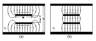 Figure 8: voltages and currents on two striplines. (a) Even-mode field distribution.(b) Odd-mode field distribution.
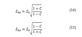 The configuration as shown in Fig. 8 is used to design a broadside coupler. The coupling coefficient can be calculated in terms of a characteristic impedance ( ). The voltage coupling coefficient ( ) is calculated from the characteristic impedances of even-mode ( ) and odd-mode ( ) which can be expressed as [30]:
According to Cohn [31]-[33], the even-mode and odd-mode characteristic impedances with respect to ground planes can be calculated by:
Where and are complete elliptic integrals of the first kind and . The ground plane spacing ( ) and the spacing between two parallel striplines ( ) are used to calculate the parameter which can be calculated by:
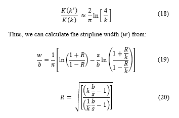 The circuit design of a 3-dB quadrature hybrid coupler, as shown in Figure 9. The top stripline is embedded between the substrate 1 and the top ground plane. The bottom stripline is embedded between the substrate 3 and the bottom ground plane. The space between the top stripline and the bottom stripline is inserted by a substrate 2, as shown in Figure 9 (a). Assume, the input signal is injected into port 1, called “input port”. The bottom stripline passes an input signal to port 3, called “directed port”. Also, an input signal is coupled via the top stripline to port 2, called “coupled port”. An input signal is divided by a 3-dB quadrature hybrid coupler into two equal amplitude outputs with a 90˚ relative phase difference. The input and coupled signals are canceled at the port 4 that has no signal going out from this port, called “isolated port”.
The hybrid coupler is implemented at the frequency of
98 MHz, It is a center frequency of FM broadcast systems. The FR-4 printed circuit broads (PCB) are used to make prototype couplers. A dielectric constant ( ) of an FR-4 PCB is 4.6 and
a substrate thickness ( ) is 0.8 mm. Assuming the characteristic impedance ( ) is 50 Ω, coupling coefficients ( ) is 0.707 The summarize calculated parameters from (14) – (20) are the stripline width ( ) 2.54 mm. The ground plane spacing ( ) is 10.4 mm. The length of a coupled line ( ) is 385 mm. The circuit of a 3-dB quadrature hybrid coupler using tightly microstrip line, as shown in Figure 9(b). This circuit designed is simulated with the CST software to verify a proposed hybrid coupler.
Due to the general FR-4 PCBs have 1.6 mm and 0.8 mm substrate thickness while the dimension of ground plane spacing ( ) of the proposed coupler is 10.4 mm. Thus, we choose an FR-4 PCB with 1.6 mm substrate thickness to make substrate 1 and substrate 3 which can be made by using PCBs piling up to three layers. The constructed of a prototype coupler is shown in Fig. 9. The overall physical dimension is 75×85 mm.
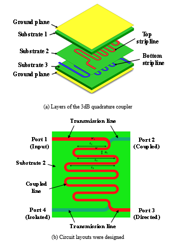 Figure 9: The configuration of a 3-dB quadrature hybrid coupler(a) Layers of the 3-dB quadrature hybrid coupler(b) Circuit layout of the 3-dB quadrature hybrid coupler
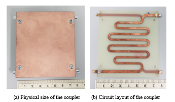 Figure 10: Photographs of theprototype coupler
4.1. Measurement Results of the Quadrature Hybrid Couplers
In this section presents the experimental results of the prototype 3-dB hybrid coupler. The frequency range between
25 MHz to 150 MHz has return losses lower than -15dB, as shown in Figure 11. The center frequency of an FM broadcasting systems (98MHz) provides a maximum coupling coefficient, as shown in Figure 12. The coupling coefficient between a signal line and
a coupler line is -3.4 dB (S21) and The transmitted coefficient between a signal line and a coupler line is -3.3 dB (S31). The relative phase difference between the two output ports is 90 ± 2˚, as shown in Figure 13. The measured isolations (S41) are lower than -17 dB. The input and coupled signals are canceled at the
port 4.
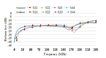 Figure 11: Measured and simulated results of the return loss
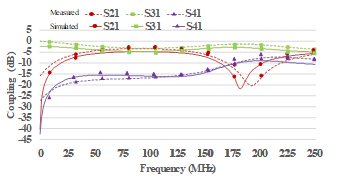 Figure 12: Measured and simulated results of the coupling coefficient
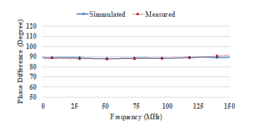 Figure 13: Measured and simulated results of the relative phase difference
5. Design and Implementation of Balanced RF Power Amplifiers
The balanced power amplifier was implemented by using two prototype 3-dB quadrature hybrid couplers. The first coupler divides an input signal into two identical single-stage amplifiers. The amplifier modules were designed for FM broadcasting systems, at 88-108 MHz frequency range, based on class-C push-pull amplifiers. The single-stage amplifier consists of 2 x MRF151 N-channel MOSFET. The bias configuration set a drain-source voltage (Vds) = 48V, drain-source current (Ids) = 0.3A and gate-source voltage (Vgs) = 2.9V. Maximum output power is 250-W with gain 14 dB. Two amplifiers have the same bias voltage which provides an equal output power capability. The output signals from two amplifiers are combined by the second quadrature coupler. The total power is transmitted to the antenna systems.
The prototype of a balanced power amplifier shows in Figure 14. The port 1 of the first couplers is an input port and the port 3 of the second couplers is an output port. Isolated ports, port 4 of first couplers and port 2 of seconded couplers, are terminated by
a dummy load 50 Ω. When the input and output impedance is poorly matched with the RF power amplifiers that are propagated signals reflected into a dummy load.
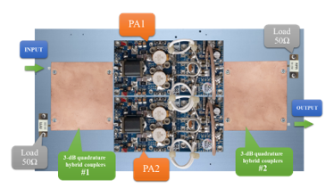 Figure 14: The configuration of a prototype balanced RF power amplifier
5.1. Measurement Results of the Balanced RF Power Amplifiers
The ROHED&SCHWARZ NRP2 Power meter is used to measure a balanced RF power amplifier. The Agilent E4421B signal generator creates an FM modulation signal and injects to the input port of a balanced amplifier. The first measurement focuses on the output power of each single-stage amplifier. The proposed balanced amplifier was tested at frequency 105 MHz that is
a reverse frequency. Output powers of each amplifier module compared to the input power level displays in Figure 15. when the input power level is 4 watt that provides the output power of two amplifiers approximately 116.20 watts and 118.90 watts respectively. The line curves of two amplifiers have been overlapped. The result shows that two amplifiers are equal output power capability which can be combined.
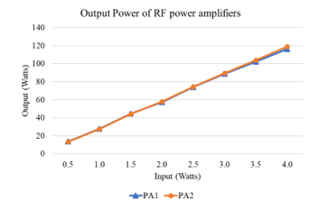 Figure 15: Measured results of the output power of each amplifier module
The second measurement focuses on the total output power of a balanced RF power amplifier. The total power is realized by the sum of two signals from two single-stage amplifiers that use the second quadrature hybrid coupler. The prototype balanced amplifier obtains an output power of 210 watts with a gain of 17.20 dB when the input power level is 4 watts. The output power has been dropped off 25.1 watts from sum signals of two amplifiers due to the insertion loss of the coupler at the output stage.
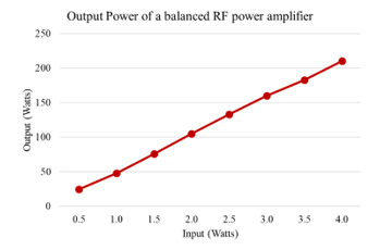 Figure 16: Measured results of the balanced RF power amplifier
6. Measurement Results of a Balanced RF Power Amplifier using to Reduce Reverse Intermodulation Products
6.1. Measurement Setup
This section presents experimental results of the FM broadcast station using a balanced RF power amplifier to reduce the reverse intermodulation. A practical setup, as shown in Figure 17, is used to demonstrate the situation of two closely located FM broadcast stations. The one FM transmitter generates a reverse frequency ( ) that is transmitted 500 watts output power at 99.50 MHz. Another FM transmitter generates a carrier frequency ( ) at 105.00 MHz. The two parallel antenna systems for a reverse frequency and a carrier frequency are installed in the same tower which has a height 60 meter. This configuration provides
a maximum level of reverse intermodulation products. The reverse transmitter uses a cavity bandpass filter in the output stage which ensures to block unwanted signals from this transmitter.
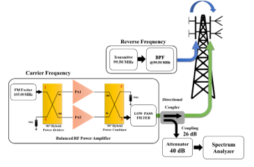 Figure 17: Measurement setup to demonstrate the situation of two closely located FM broadcast stations.
Two transmitters are measured in this research. The first transmitter uses a single-stage RF power amplifier, based on a class-C push-pull, and the second transmitter uses a prototype balanced amplifier in this research. Two transmitters are used to generate a carrier frequency ( ) that is transmitted 200 watts output power at 105.00 MHz. Almost output signals from a transmitter is measured via a directional coupler with a coupling value of 26 dB and an attenuator of 40 dB. Intermodulation products are provided in terms of and that are a frequency of 94.00 MHz and 110.50 MHz respectively. Since the frequency of 110.50 MHz is out of an FM frequency band and falls into the frequency range of Air Traffic Control systems. Therefore, the measurement results consider the intermodulation product in terms of only.
6.2. Measurement Results of the FM transmitters using a single-stage power amplifier.
Measurement results of a carrier transmitter using a single-stage power amplifier present in Figure 18. The carrier transmitter transmits an FM modulation signal that is the frequency of 105.00 MHz without cavity bandpass filters. The signal strength of a reverse frequency, at the frequency of 99.50 MHz, is -42.35 dBm that is a signal traveling until it present at the output state of the carrier transmitter, port 3 of the second quadrature coupler. The output power of a carrier frequency at 105.00 MHz is -17.55 dBm and the intermodulation level at 110.50 MHz is 30.87 dBc.
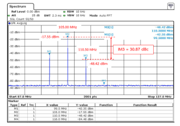 Figure 18: Intermodulation level of the FM transmitter using a single-stage RF power amplifier
6.3. Measurement Results of the FM transmitters using a Prototype Balanced RF Power Amplifier
The FM transmitter using a prototype of a balanced RF power amplifier is measured that is compared with a single-stage RF power amplifier. The output power of a balanced amplifier must be adjusted equal to a single-stage RF power amplifier. From Figure 17, the frequency spectrum shows that the signal strength of a reverse frequency at 99.50 MHz is -50.89 dBm which is decreased by 8.54 dBm. The output power of a carrier frequency at 105.00 MHz is -16.50 dBm and the intermodulation level is 49.34 dBc. Table 1 shows a comparison of the measurement results of two FM transmitters that use a single-stage RF power amplifier and a balanced RF power amplifier. It shows that both transmitters provide the same power level which is approximate -17 dBm. A power level of a reverse frequency is less than a single-stage RF power amplifier. The balanced RF power amplifier provides a good performance that improvements an intermodulation level from 30.84 dBc to 49.34 dBc. Measurement results are according to the analysis in section 3. The results show the mitigation of an intermodulation signal that is approximate 18.47 dBc without cavity bandpass filters. The mitigation intermodulation signal is difficult to obtain a maximum reduction due to the quadrature hybrid couplers have slightly different amplitudes and phases.
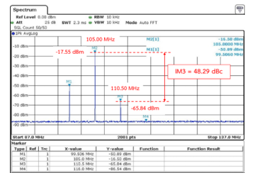 Figure 19: Intermodulation level of the FM transmitter using an FM transmitter using a Balanced RF Power Amplifier
Table 1: Measurement results of two FM transmitters.
| Signal Strength | |||
|
Frequency (MHz) Amplifier types |
99.50 | 105.00 | 110.50 |
| (dBm) | (dBm) | (dBc) | |
| The single-stage RF power amplifier |
-42.35 | -17.55 | 30.87 |
| The balanced RF Power Amplifier |
-50.89 | -16.50 | 49.34 |
| ∆ | -8.54 | 1.05 | 18.47 |
7. Conclusions
This paper proposes a balanced RF power amplifier using the improvement 3-dB quadrature hybrid couplers to reduce the reverse intermodulation of FM broadcast stations. The balanced RF power amplifier was implemented by using the prototype 3-dB quadrature hybrid couplers. The FR-4 low-cost PCB with a broadside-coupled striplines technique is chosen to construct prototype couplers that can reduce the overall size of a hybrid coupler and suitable to use for balanced RF power amplifies. Experimental results of the prototype coupler, The return loss is lower than -15 dB. The coupled port has a coupling coefficient
-3.4 dB and the directed port has a coupling coefficient -3.3 dB. The phase difference between a coupled and directed port is
90 ± 2˚. Isolation values are lower than -17 dB. The overall size of the prototype couplers is 75x 85 mm. We apply a prototype 3-dB quadrature hybrid couplers to a balanced power amplifier which are structured from two identical quadrature couplers and two signal-stage amplifiers. The two identical single-stage amplifiers use a class-C RF amplifier with the MRF151 N-channel MOSFET and operate at the frequency range of 88-108 MHz. A balanced amplifier obtains an output power of 210 watts with a gain of
17.20 dB when the input power level is 4 watts.
The situation of two closely located FM broadcast stations is used to create the reverse intermodulation signal. The one transmitter generates a reverse signal ( ) at 99.50 MHz that is transmitted 500 watts output power and another transmitter generate a carrier signal ( ) at 105.00 MHz. The antenna systems for two frequency are installed in the same tower which has height 60 meters. Two carrier transmitters which use a balanced RF power amplifier and a single-stage RF power amplifier are measured. The carrier transmitter using a balanced RF power amplifier improvements an intermodulation level from 30.84 dBc to 49.34 dBc. The results show the mitigation of an intermodulation signal approximate 18.47 dBc without cavity bandpass filters. The mitigation intermodulation signal is difficult to obtain a maximum reduction due to the quadrature hybrid couplers have slightly different amplitudes and phases.
Acknowledgment
This work was supported by The National Broadcasting and Telecommunications Commission (NBTC) of Thailand and the Research Department Institute of Engineering, Suranaree University of Technology (SUT), Nakhon Ratchasima, Thailand.
- David Hand C.Eng MIET, “THE RF CHALLENGES OF ATC COMMUNICATIONS” Consultant Engineer – Park Air Systems Ltd.
- Jaiyen, N., Hantula, P., & Tongta, R. (2017, December). Real-time audio similarity comparison algorithm. In 2017 IEEE 15th Student Conference on Research and Development (SCOReD) (pp. 477-480).
- Hantula, P., Jaiyen, N., & Tongta, R. (2018, August). A 3-dB Quadrature Coupler Using Broadside Striplines for FM Power Amplifiers. In 2018 IEEE International Workshop on Electromagnetics: Applications and Student Innovation Competition (iWEM) (pp. 1-2).
- Alcon Garcia, P., Esparza Lopez, N., Herran Ontanon, L. F., & Las Heras Andres, F. (2016). Complex Impedance Transformers Based on Branch-Line Hybrid Couplers. Progress In Electromagnetics Research, 69,
147-157. - Jung, S. C., Negra, R., & Ghannouchi, F. M. (2008). A design methodology for miniaturized 3-dB branch-line hybrid couplers using distributed capacitors printed in the inner area. IEEE Transactions on Microwave Theory and Techniques, 56(12), 2950-2953.
- Hussein, Ehab Abdul Razzaq, and Mohammed A. Abdulkadhim. “Performance improvement of BER in OFDM system using feed forward technique on power amplifier.” International Journal of Computer Applications 75.4 (2013).
- Amanpreet Kaur, Rajbir Kaur “Reducing the Third-Order Inter Modulation Distortion by Feed Forward Linearization of Power Amplifier” International Journal of Advanced Research in Computer and Communication Engineering Vol. 5, Issue 1, January 2016
- Parsons, K. J., R. J. Wilkinson, and P. B. Kenington. “A highly-efficient linear amplifier for satellite and cellular applications.” Global Telecommunications Conference, 1995. GLOBECOM’95. , IEEE. Vol. 1. IEEE, 1995.
- Grebennikov, Andrei. “Linearity Improvement Techniques for Wireless Transmitters: Part 2.” High frequency electronics (2009): 16-26.
- Katz, Allen, et al. “Sensitivity and mitigation of reverse IMD in power amplifiers.” Power Amplifiers for Wireless and Radio Applications (PAWR), 2011 IEEE Topical Conference on. IEEE, 2011.
- Berglund, Bo, Thorsten Nygren, and Karl-Gosta Sahlman. “RF multicarrier amplifier for third-generation systems.” ERICSSON REV (ENGL ED) 78.4 (2001): 184-189.
- Ma, Hongbo, and Quanyuan Feng. “An improved design of feed-forward power amplifier.” PIERS Online 3.4 (2007): 363-367.
- Tsai, K. Y., Yang, H. S., Chen, J. H., & Chen, Y. J. E. (2011).
A miniaturized 3 dB branch-line hybrid coupler with harmonics suppression. IEEE Microwave and Wireless Components Letters, 21(10), 537-539. - Sun, K. O., Ho, S. J., Yen, C. C., & van der Weide, D. (2005). A compact branch-line coupler using discontinuous microstrip lines. IEEE Microwave and Wireless Components Letters, 15(8), 519-520.
- Caillet, M., Clenet, M., Sharaiha, A., & Antar, Y. M. (2009). A compact wide-band rat-race hybrid using microstrip lines. IEEE Microwave and Wireless Components Letters, 19(4), 191-193.
- Li, H., Zhang, H. L., Hu, B. J., Wei, X. D., & Zeng, W. (2015, September). Novel wideband quadrature hybrid coupler with tunable power dividing ratio. In Signal Processing, Communications and Computing (ICSPCC), 2015 IEEE International Conference on (pp. 1-4). IEEE.
- de Paco, P., Verdu, J., Menendez, Ó., & Corrales, E. (2008). Branch-line coupler based on edge-coupled parallel lines with improved balanced response. IEEE Transactions on Microwave Theory and Techniques, 56(12), 2936-2941.
- Vijayaraghavan, A. S., & Dunleavy, L. (2011). Design and optimization of lumped element hybrid couplers. High Frequency Electronic.
- Moubadir, M., Aziz, H., Touhami, N. A., & Mohamed, A. (2018).
A miniaturized branch-line hybrid coupler microstrip for long term evolution applications. Procedia Manufacturing, 22, 491-497. - Breed, G. (2009). Transmission line and lumped element quadrature couplers. High Frequency Electronics.
- Kajfez, D., Paunovic, Z., & Pavlin, S. (1978). Simplified design of Lange coupler. IEEE Transactions on Microwave Theory and Techniques, 26(10), 806-808.
- Mao, S. G., & Wu, M. S. (2007). A novel 3-dB directional coupler with broad bandwidth and compact size using composite right/left-handed coplanar waveguides. IEEE Microwave and wireless components letters, 17(5), 331-333.
- Gruszczynski, S., Wincza, K., & Sachse, K. (2006). Design of compensated coupled-stripline 3-dB directional couplers, phase shifters, and magic-T’s—Part I: Single-section coupled-line circuits. IEEE transactions on microwave theory and techniques, 54(11), 3986-3994.
- Javadzadeh, S. M. H., Majedi, S. M. S., & Farzaneh, F. (2010, September). An ultra-wideband 3-DB quadrature hybrid with multisection broadside stripline tandem structure. In International Conference on Mobile Multimedia Communications (pp. 672-681). Springer, Berlin, Heidelberg.
- Chang, C. P., Chiu, J. C., Chiu, H. Y., & Wang, Y. H. (2008). A 3-dB quadrature coupler using broadside-coupled coplanar waveguides. IEEE Microwave and Wireless Components Letters, 18(3), 191-193.
- Chiu, J. C., Lin, C. M., & Wang, Y. H. (2006). A 3-dB quadrature coupler suitable for PCB circuit design. IEEE transactions on microwave theory and techniques, 54(9), 3521-3525.
- Abdolhamidi, M., Mohammad-Taheri, M., & Ali-Abad, M. A. A “Design Equations for Broadside and Edgewise Stripline Couplers”.
- May, J. W., & Rebeiz, G. M. (2008). A 40-50-GHz SiGe 1: 8 differential power divider using shielded broadside-coupled striplines. IEEE Transactions on Microwave Theory and Techniques, 56(7), 1575-1581.
- Bhartia, P., & Pramanick, P. (1988). Computer-aided design models for broadside-coupled striplines and millimeter-wave suspended substrate microstrip lines. IEEE transactions on microwave theory and techniques, 36(11), 1476-1481.
- Bahl, I. J., & Bhartia, P. (1981). The design of broadside-coupled stripline circuits. IEEE Transactions on Microwave Theory and Techniques, 29(2), 165-168.
- Cohn, S. B. (1960). Characteristic impedances of broadside-coupled strip transmission lines. IRE Transactions on Microwave Theory and Techniques, 8(6), 633-637.
- Hilberg, W. (1969). From approximations to exact relations for characteristic impedances. IEEE Transactions on Microwave Theory and Techniques, 17(5), 259-265.
- Raab, F. H., Asbeck, P., Cripps, S., Kenington, P. B., Popovic, Z. B., Pothecary, N. and Sokal, N. O. (2003). RF and microwave power amplifier and transmitter technologies Part 3. High Frequency Electronics, 2(3),
22-36.