
Hidden Surface Removal for Interaction between Hand and Virtual Objects in Augmented Reality
Volume 4, Issue 4, Page No 359-365, 2019
Author’s Name: Takahiro Ishizu1, Makoto Sakamoto1,a), Masamichi Hori1, Takahiro Shinoda1, Takaaki Toyota1, Amane Takei1, Takao Ito2
View Affiliations
1Department of Computer Science and System Engineering, University of Miyazaki, 889-2192, Japan
2Institute of Engineering, Hiroshima University, 739-8511, Japan
a)Author to whom correspondence should be addressed. E-mail: sakamoto@cs.miyazaki-u.ac.jp
Adv. Sci. Technol. Eng. Syst. J. 4(4), 359-365 (2019); ![]() DOI: 10.25046/aj040444
DOI: 10.25046/aj040444
Keywords: Augmented Reality (AR), Virtual object, Occlusion problem, Canny edge detection, Hidden surface removal, Hand area

Export Citations
Recently, augmented reality (AR) technology has been applied to the inter- action technology between human and virtual objects. In AR interaction technology, it is necessary for users to be able to manipulate virtual objects intuitively. Thus, we focus on manipulating virtual objects directly with the user’s bare hands in this study. On the other hand, in AR technology, since the 3-dimensional (3D) model is superimposed on the image of the real space afterwards, it is always displayed on the front side than the user’s hand (occlusion problem). Thus, it becomes an unnatural scene in some cases. In this study, this system detects hand area of the user by extracting depth information, color information and using canny edge detection in the user’s hand. Thus, this system performs hidden surface removal along the area of the user’s hand by considering the object-context relations between the user’s hand and the virtual object. In the evaluation experiment, it is confirmed that the hidden surface removal in this study make it possible to distinguish between finger boundaries and to clarify and process finger contours. This work is an extension of the paper entitled “Hidden Surface Processing for Interaction of Hand and Virtual Objects Using Leap Motion Controller” published in 2018 International Conference on Informationand Communication Technology Robotics (ICT-ROBOT).
Received: 31 May 2019, Accepted: 27 July 2019, Published Online: 19 August 2019
1. Introduction
Augmented reality (AR) is used in many fields including education, medicine and entertainment, and its applications became widespread [1, 2, 3]. Also, the interaction with the virtual objects is required in those papers. Therefore, we think that more precise virtual object manipulations in AR will be performed in the future.
On the other hand, since hands are our main means of interaction with objects in real life, AR interfaces should also be able to be for free hand interaction with virtual objects.
Furthermore, it is important to be able to adapt to more detailed tasks by hand in order to handle a wide range of fields such as medical care and education.
In the conventional study [4], by putting a marker, a special glove, etc. on a user, the user’s position information was acquired and interaction with a virtual object was realized. However, these methods may give the user a sense of discomfort such as weight due to wearing. Therefore, bare hand interaction is required.
However, since the 3-dimensional (3D) model displayed
and user’s hand is hidden by virtual objects. Thus, the scene may become an unnatural scene, and the user cannot see the object-context relations of the virtual object and his/her hand, and feels that it is difficult to manipulate the virtual objects.
In the existing study [5], the system used transparent 3D models and the 3D models followed each fingers of the user based on the depth information of the user’s hand. In this way, they performed hidden surface removal and tackled the occlusion problem. However, since the 3D models which follow the user’s fingers are larger than the finger, a wider range than the actual finger was displayed on the front (see Figure 1). In addition, no description has been given of a case where there is a multiple virtual objects in the existing study.
In other related study [6], using the Kinect sensor in order to obtain depth information of the user, hidden surface removal was realized when an arm was inserted between multiple virtual objects. Also, it was the same even when it came to deformable virtual object. However, the Kinect sensor is a sensor that roughly recognizes human motion and depth information, and the study didn’t focus on the interaction between hands and virtual objects.
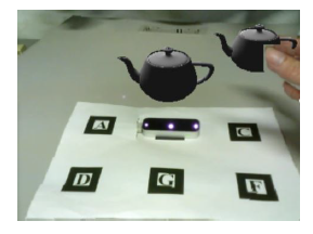 Figure 1: Hidden surface removal in existing study
In this study, we use Leap Motion Controller to acquire depth information of the user’s hand. Additionally, this system acquires RGB (Red, Green and Blue) information from the web camera. Based on these pieces of information, the contour of the hand is extracted to realize hidden surface removal along the contour of the hand.
In this study, we aim to cope with more detailed virtual object manipulations by conducting hidden surface removal along the outline of the user’s hand. Moreover, we conduct a manipulation of grasping a virtual object of primitive model by hand and confirm whether it works properly.
2. Proposal
In order to conduct hidden surface removal along the contour of the user’s hand, this system detects hand area of the user by extracting depth information, color information and edge detection in the user’s hand.
First, in order to extract hand area, we use the RGB image based on color information. Next, based on the depth information of the hand, a blue point group is created on the thumb, and a green point group is created on the other fingers. These point groups are displayed at their positions only when the hand is in front of the virtual object. In addition, the hidden surface removal along the fingers is realized by using the hand area extracted first and the result of edge detection. Also, in order to cope with multiple virtual objects and distinguish the object-context relations of the blue point group and the green point group, we use the Z-buffer method.
In this way, when the user’s hand is near from camera than the virtual object, the user’s hand is correctly displayed on the front side of the virtual object, and the user can grasp the anteroposterior relationship between the user’s hand and the virtual object.
2.1. System Component
This system consists of a Web camera, the Leap Motion Controller, PC and AR marker. In this study, since this system needs accurate position information of user’s fingers, we use the Leap Motion Controller that can acquire various data relating to user’s hand with high accuracy.
The purpose of use of each of the devices shown above is as follows:
- Web camera: Acquisition of real image and recognition of marker.
- The Leap Motion Controller: Obtaining 3D coordinates of the user’s fingers.
- Monitor: Video output.
- AR marker: Acquisition of position and tracking of virtual objects.
The Leap Motion Controller and the webcam both use camera features, which causes the camera features to interfere with each other. Therefore, this system addresses this problem by using network programming. This system acquires data of 3D coordinates of the user’s fingers with the Leap Motion Controller on the server side. In addition, this system sends the data to the client side. On the other hand, this system acquires images with the Web camera, and conducts image processing and video output using the data which received from the server side on the client side.
This system controls the position and orientation of the virtual objects is by recognizing the AR marker. Therefore, the AR marker needs to be recognized by the web camera. However, when the user manipulates virtual objects, the AR marker may be covered by his/her own hand. Therefore, this system adopts a method of treating Marker A to Marker F as one marker (see Figure 2). Thus, even when a part of the marker is covered, the virtual objects can be displayed properly.
We place the Leap Motion Controller on the position of Marker B. This system displays the virtual objects on the position of Marker C and Marker G (see Figure 2).
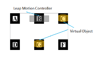 Figure 2: AR marker
2.2. Development Environment
We use ARToolKit for AR marker recognition and camera control. And, we develop this system using OpenGL for displaying virtual objects and OpenCV for various image processing. Here, the resolution of the camera is 320 × 240 pixels.
2.3. Flow of Image Processing
The processing flow comprises of several steps as shown in Figure 3. In Figure 3, the block of light red background indicates that it is generated image.
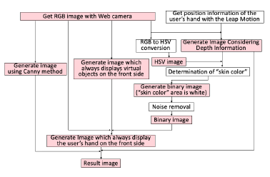 Figure 3: Flow of image processing in this system
2.4. Processing of Camera Image
This system gets RGB image with the web camera (see Figure 4). In this study, in order to use the HSV (Hue, Saturation and Value) color space often used in the processing of color images, this system converts RGB images to the HSV color space.
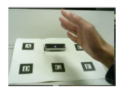 Figure 4: RGB Image
2.5. Generation of Binary Image
2.5.1 Determination of “skin color”
This system needs to extract the area of skin color for detection of the user’s hand area. At first, this system puts red point on the finger which are the closest to the camera (see Figure 5). A certain range is given to the HSV value obtained from the pixel of that point, and it is defined as ”skin color”.
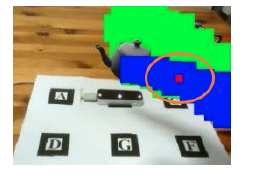 Figure 5: Red point
Next, this system detects the user’s hand area as binary images.
The procedure is shown below.
- Get the 3D coordinates of the proximal phalanx of the finger which are the closest to the camera with the Leap Motion Controller.
- Generate images that red point is plotted around the acquired position.
- Obtain the 2D coordinate value of pixel units in the red point.
- In Figure 4, this system gets average values of HSV in the pixel values corresponding to the coordinates acquired in step 3.
- Apply an appropriate range to each value of Hue, Saturation, Value and decide it as “skin color”.
2.5.2 Noise removal
The binary image generated by this system contains salt and pepper noise at first. Therefore, this system conducts erosion and dilation twice in 8-neighbor in order to remove noise.
However, that alone cannot remove the noise sufficiently (see Figure 6). This is because, in this method, this system has to conduct erosion and dilation multiple times in order to remove loud noise. However, it needs complicated calculation.
Therefore, regarding to the loud noise, this system removes the noise in the area of the hand by conducting the following processing (see Figure 7).
- Determine white area including red point (which is put on the finger which is closest to the camera) as hand area.
- Fill the inside of the hand area with black and the outside of the hand area with white.
- Invert white and black.
In this way, all noise in the hand area is removed (see Figure 8).
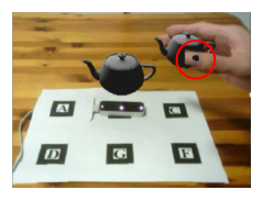 Figure 6: Result image including noise
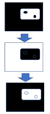 Figure 7: Noise removing process
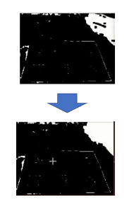 Figure 8: Noise removing
2.6. Generate Image Considering Depth Information
This system acquires 3D coordinates of the distal bone, middle phalanx, basal bone and metacarpal bone of the user’s hand (see Figure 9) with Leap Motion Controller.
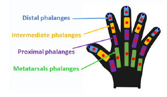 Figure 9: Hand joint
Based on the acquired position information of the fingers, this system generates images plotting blue point group (following the position of the thumb) and green point group (following the position of a finger other than the thumb).
Blue point group displays at the positions of each joint of the thumb when the user’s thumb is front of the back object (see Figure 10).
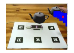 Figure 10: Blue point group following the thumb
In addition, green point group displays at the positions of each joint of the fingers except thumb when the user’s fingers except thumb are front of the back object (see Figure 11).
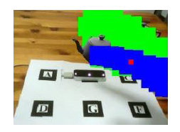 Figure 11: Blue point group and green point group following the whole hand
Furthermore, this system makes it possible to handle multiple virtual objects of different depths. The object-context relations between the back virtual object and the hand of the user is determined depending on whether or not blue point group and green point group are displayed. On the other hand, the object-context relations between the virtual object on the near side and the user’s hand is determined by using the Z-buffer method. Using the Z-buffer method, when a finger is positioned behind the virtual object, blue point group and green point group following the position of the finger are hidden by the virtual object. In this way, this system can determine the object-context relations between the user’s hand and the virtual objects even if there are multiple virtual objects.
2.7. Generate Images which Always Display The Hand in Front of Virtual Objects
This system synthesizes the original RGB image (see Figure
12-a) only in the white area in Figure 13 to the image in Figure 12-b. Thus, this system generates images that the user’s hand is always displayed on the front of the virtual object (see Figure 12-c).
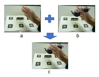 Figure 12: Generation of images which hand is displayed front
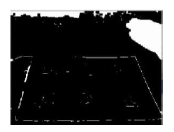 Figure 13: Binary image
2.8. Generate Result Images
The area in Figure 12-b corresponding the area of the blue point group, the green point group and the red point group (in the case where the position of the proximal phalanges of thumb is in front of the virtual object) of Figure 14-a are replaced with the image shown in Figure 14-b (Figure 12-c). Thus, based on the depth information, this system generates images that the hand is displayed in front of the virtual object (see Figure 14-c).
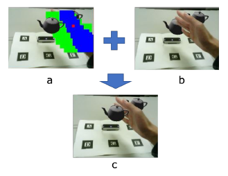 Figure 14: Generation of result images
2.9. Distinction between Fingers Using Canny Edge Detection
The white area in Figure 13 indicates the hand area. However, no distinction between fingers is made from this image.
Therefore, if hidden surface removal is conducted based on this image, even if only the thumb should be subjected to hidden surface removal like Figure 15, other fingers are involved and processing is conducted.
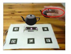 Figure 15: Involved other fingers
Therefore, we need edge detection of the user’s thumb in order to solve this problem.
Edge detection is the name for a set of mathematical methods which aim at identifying points in a digital image at which the image brightness changes sharply or more formally, has discontinuities. The point at which image brightness changes sharply are typically organized into a set of curved line segments termed as edges.
We need to detect finger edge in order to distinguish between thumb and other fingers. Furthermore, at the time of the edge detection, the edge must be one clear line, since the area of the thumb extracted by edge detection is filled in the area surrounded by the edges in the later processing.
In this study, we use Canny edge detection algorithm [7] to find an edge of the user’s thumb. Because it provides better results and efficiency than other available algorithm when we want to detect clear edges [8].
Canny edge detector uses two thresholds and if the intensity of that pixel is below that lower threshold than it is assigned “0” value that can be none edge and if the intensity of any pixel is above that the higher threshold than it is assigned “1” value and can be edge.
In this study, we distinguish the thumb from the other fingers. In order to detect the thumb, the thumb is surrounded by an ellipse, and the inner area surrounded by it and the boundary displayed by edge detection is extracted. The area is the thumb area (see Figure 16).
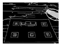 Figure 16: Extraction of the thumb area
The following process is conducted to detect the thumb.
- Get two coordinates of upper left end and lower right end of blue point group (see Figure 17-a).
- Make an ellipse based on a line connecting the two points (which are the coordinates acquired in step 1).
- Overlap the ellipse surrounding the thumb on the image generated based on the Canny edge detection (see Figure 17-b).
- Fill the area surrounded by the ellipse and the edge in Figure 17-b which corresponding to the position including the red point group in Figure 17-a with gray. 5. Regards this gray area as the thumb area.
In this way, this system generates result image (see Figure 17-c).
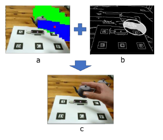 Figure 17: Distinction between the thumb and the other fingers
3. Experimental Results
We executed this system to confirmed whether hidden surface removal along the fingers is possible or not.
First, we checked whether this system can cope with multiple virtual objects. In this system, the object-context relations between the back virtual object and the hand of the user is determined depending on whether or not blue point group and green point group are displayed. In order to confirm whether this is properly processed, we placed the virtual object at position C in Figure 2 and performed manipulation that a user grabs the virtual object. On the other hand, the object-context relations between the virtual object on the near side and the user’s hand is determined by using the Z-buffer method. In order to confirm whether this is properly processed, we placed the virtual object at position G in Figure 2 and performed manipulation that a user grabs the virtual object.
Furthermore, we performed grasping manipulations on virtual objects of 3D primitive figures from various directions in order to confirm whether this system is applicable to virtual objects of various shapes.
3.1. In the case of an object behind
Since only the thumb comes to front side than Marker C, the blue point group follows only the thumb (see Figure 10) and draw the thumb properly on the front of the virtual object (see Figure 18).
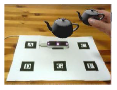 Figure 18: Result at the position of C in the AR marker
3.2. In the case of an object in front
This system conducted the hidden surface removal considering multiple virtual objects by the Z-buffer method. The blue point group follows only the thumb and the green point group follows the other fingers (see Figure 11). Besides, only the point group of the thumb was drawn on the front of the virtual object by the Z-buffer method. As a result, it was possible to draw only the thumb on the front (see Figure 19). The blue point group and green point group in Figure 11 are based on the depth information of the user’s fingers. Also, the anteroposterior relationship between the blue point group and the green point group is correctly displayed by the Z-buffer method. In this way, when the thumb is positioned behind the other fingers, the green point group is displayed on the front side of the blue point group.
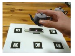 Figure 19: Result at the position of G in the AR marker
3.3. Various trials
We tested three movement patterns for each 3D objects. Here, we use cube (see Figure 20), cone (see Figure 21) and torus (see Figure 22) as 3D primitive objects.
In this section, we display the virtual object at position B.
Each movement is as follows.
- Grip the virtual object from the side.
- Grip the virtual object from the top.
- Grip the virtual object while the user’s thumb is behind the other fingers.
The results are shown below. Here, “Grip the virtual object from the side”, “Grip the virtual object from the side”, and “Grip the virtual object from the side” in order from the left in Figure 20 – Figure 22.
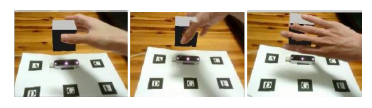 Figure 20: Cube
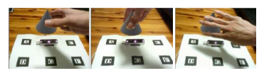 Figure 21: Cone
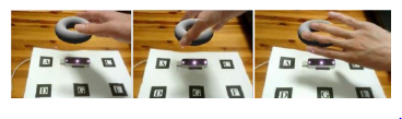 Figure 22: Torus
4. Consideration
We confirmed that this system can perform correctly hidden surface removal even when a user manipulates multiple virtual objects by Z-buffer method from the experiment result. In addition, we also confirmed that this system is effective for virtual objects of various shapes.
The distinction between the virtual object and the user’s hand was not clear when using the Z-buffer method when considering the depth between the virtual object and the user’s hand. Therefore, if there is only one virtual object or if the depth coordinates of the virtual objects are all at the same position, it is better to have blue point group follow the thumb of the user only than to have blue point group and green point group follow the palm of the user’s hand.
Regarding gripping the virtual object from the side (see Figure 20), it was confirmed that the hidden surface removal was accurately distinguished without involving a nearby finger.
Regarding gripping the virtual object from the top (see Figure 21), sometimes the hidden surface removal of the base of the thumb did not work well, and a virtual object was displayed superimposed on the thumb. This is because the area of the thumb extracted by the Canny method is smaller than the area of the real thumb.
Regarding gripping the virtual object while the user’s thumb is behind the other fingers (see Figure 22), it was confirmed that the hidden surface removal was properly treated even when the fingers other than the thumb were on the near side. This is an effect of the present system because the determination of the skin color is conducted on the foremost finger. Also, at this time, since the blue point group is moved to the back from the green point group, processing such as the Canny method for the thumb is ignored.
5. Conclusion
The future of AR as interaction technology in users and virtual objects looks bright. In recent years, AR has been applied to a wide range of fields such as education, medicine, entertainment and a guide for various tasks. Among them, the user directly manipulates virtual objects with their bare hands. In the future, we expect further development of interaction manipulation, and more detailed virtual object manipulation will be required.
Thus, we proposed and implemented hidden surface removal along the fingers, aiming at being able to apply to more detailed works about interaction manipulation in AR. In this study, we paid attention to detection the contour of the hand to realize hidden surface removal along the user’s fingers. In this system, processing based on hand depth information, color information and edge detection is conducted to detect hand contours.
As for edge detection, the Canny method was used to reduce noise and obtain a clear contour. By these processes, appropriate hidden surface removal was realized without involving other fingers.
In the evaluation experiment, it was shown that it can cope with multiple virtual objects. In addition, we tested various grip methods for virtual objects of various shapes, and showed that they manipulate normally.
As future works, since the generation of binary images is not stable at the time of skin color detection, it needs the solution. Moreover, since the contour of the thumb is interrupted at the time of the Canny edge detection, it needs to set more appropriate threshold in Canny edge detection.
- Kangdon Lee, “Augmented Reality in Education and Training”, TechTrends, vol.56, no.2, pp.13-21, 2012.
- Carmigniani J, Furht B, Anisetti M, Ceravolo P, Damiani E, Ivkovic M, “Augmented reality technologies, systems and applications”, Mul-timedia Tools and Applications 51:341-77, 2011.
- Abdelkader Bellarbi, Christophe Domingues, Samir Otmane, Samir Benbelkacem and Alain Dinis, “Underwater augmented reality game using the DOLPHYN”, Proceedings of the 18th ACM symposium on Virtual reality software and technology, ACM, 2012.
- Buchmann V, Violich S, Billinghurst M, Cockburn A. “FingARtips –Gesture Based Direct Manipulation in Augmented Reality”, 2nd inter-national conference on computer graphics and interactive techniques, ACM Press, pp.212–221
- R. Katahira, M. Soga. “Development and Evaluation of a System for AR enabling Realistic Display of Gripping Motions using Leap Motion Controller”, Procedia Computer Science 60:1595–1603, 2015.
- J. Adri´an Leal-Mel´endrez, Leopoldo Altamirano-Robles, and Jesus A. Gonzalez. “Occlusion Handling in Video-based Augmented Reality Using the Kinect Sensor for Indoor Registration”, Progress in Pattern Recognition, Image Analysis, Computer Vision, and Applications: 18th Iberoamerican Congress, CIARP 2013, Proceedings, Part II, 2013.
- J. Canny. “A Computational Approach to Edge Detection”, IEEE Trans. Pattern Analysis and Machine Intelligence, vol.8, no 6, pp.679-698, 1986.
- Abhinandan Julka and Sandeep Bhargava. “A Static Hand Gesture Recognition Based on Local Contour Sequence”, International Journal of Advanced Research in Computer Science and Software Engineer-ing, Volume 3, Issue 7, 2013.