
Model-Driven Engineering Infrastructure and Tool Support for Petrochemical Industry Automation
Volume 4, Issue 4, Page No 174-187, 2019
Author’s Name: Thaise Poerschke Damo1,a), Leandro Buss Becker1, Fabio Paulo Basso2
View Affiliations
1Federal University of Santa Catarina (UFSC), Automation and Control Systems Department, 88066-040, Brazil
2Federal University of Pampa (UNIPAMPA), Campus Alegrete, 97546-550, Brazil
a)Author to whom correspondence should be addressed. E-mail: thaisedamo@gmail.com
Adv. Sci. Technol. Eng. Syst. J. 4(4), 174-187 (2019); ![]() DOI: 10.25046/aj040422
DOI: 10.25046/aj040422
Keywords: Model-Driven Engineering, Object-Orientation, Industrial Automation

Export Citations
The definition of equipment and components of physical plants is a necessary step towards the development of simulation, control, and supervisory applications for the petrochemical industry. Often it happens that the same plant/equipment is (re)modeled on each application, causing a waste-oftime on repetitive (re)design, besides introducing potential inconsistencies between the models. Moreover, even though each software platform normally o_ers a di_erent view of the same plant, it is desirable to have some kind of interoperability between them. This paper presents a solution for such issues named M4PIA, which consists in a Model-Driven Engineering (MDE) tool support developed mainly for petrochemical industry automation. M4PIA allows representing industrial plants by means of di_erent and interchangeable object-oriented models, providing means to perform automatic code generation from a plant specification for di_erent software platforms. Currently, our work involves using M4PIA in high-level automation manouvers and plant simulations. Evaluations studies performed with M4PIA shows that it covers most features expected from a MDE tool suite. Besides, the use of M4PIA is expected to result in less development time and costs, while it increases e_ciency, maintainability, and reliability of the developed applications.
Received: 03 June 2019, Accepted: 16 July 2019, Published Online: 30 July 2019
1. Introduction
There is no doubt that todays industrial environments are highly automated, at least in the first two layers of the ISA95 automation pyramid. The most basic layer, named Field Level, includes devices, actuators, and sensors. The Control level is immediate above, and accounts with PLCs and PIDs to control such devices. Programming PLCs and PIDs is typically done by means of integrated development environments (IDEs) that comply with international standards IEC 61131-3 [1] and IEC 61499 [2]. Rarely this kind of system does not make use of SCADA (supervisory control and data acquisition) in a third Supervisory layer.
The IEC 61131-3 standard [1] addresses PLC programming, including four programming languages and sequential function charts (SFC). It helps migrating software developed for one PLC type to PLCs of other vendors. Targeting distributed systems, the IEC 61499 standard [2] replaces the cyclic execution model of IEC 61131 by an event-driven execution model, which allows an explicit specification of the execution order of function blocks (FB). Both standards cess operations there is the ISA 106 standard [3], which is typically deployed at the Supervisory level. Examples of commercial tools therefore are Exapilot from Yokogawa and GenSym G2 from Ignite Technologies. The present work stands at this layer, and makes use of a proprietary tool with similar goals named MPA [4].
Another common need in automation systems, specially when advanced control techniques come to play, is performing simulations. Examples of tools for such purposes are Labview, Matlab/Simulink, and Modelica-based (like Dymola and OpenModelica). These tools provide powerful simulation cores, and also provide a vast library of components that allow designers to build virtually every system or system element they want to. It happens, however, that there is no specific semantics for equipment specification.
Considering an automation plant, the lack of semantics for equipment specification brings difficulties for representing this same automation plant in the different software development tools used in all automation levels. Such repeated representation is something quite common, for instance, to implement different perspectives in the automation domain:
processes operation, monitoring, simulation, and control.
The work presented in this paper targets the integration of different perspectives in petrochemical industry automation through a tool support built on the Model-Driven Engineering (MDE) paradigm [5]. MDE is built on widespread techniques in Systems and Software Engineering, presenting the following main characteristics: (1) uses models in all the phases of software development to improve understanding; (2) raises the abstraction level of software system specifications, hiding platform-specific details; (3) develops Domain-Specific Languages (DSLs) [6] and frameworks to suit a domain; and (4) applies transformations to automate repetitive activities and improve product quality derived from Software Engineering (e.g., source code, libraries, processes, etc.) [7]. In other words, MDE proposes representation of diverse artifacts through modeling and tool support.
This paper presents M4PIA (Model-Driven Engineering for Petrochemical Industry Automation), which consists of an infrastructure and tool support to help the design of advanced control applications for the Petrochemical Industry. An evaluation of the proposal is also presented. Therefore, the remainder parts of this paper are organized as follows: Section 2 presents background information that motivates this research, highlighting the application domain and related works. Section 3 details the proposed M4PIA infrastructure and tool support. Section 4 shows the evaluation method employed for assessment. Section 5 details M4PIA assessment and presented obtained results. Section 6 highlights our conclusions and future works perspective.
2. Background
2.1. Advanced Control in the Petrochemical Industry
This work targets the design of advanced control strategies for the Petrochemical Industry. The advanced control does not intend to control the automation plant devices (valves, motors, etc) located in the Field Level of the automation plant. This low-level control should be done by the regulatory control in the upper, Control level, that executes on the PLCs. The advanced control stands at the Supervisory level.
For example, let us analyze the design cycle of an advanced control system for oil extraction platforms. Initially, designers should create a software-in-the-loop (SIL) environment, where the phenomena to be controlled (e.g. gas compression) is “executed” within a simulation tool (Labview, Simulink, Modelica) that communicates with the control software executing in the same hardware platform that will be used in the final system. Here, the automation plant elements are represented twice: (1) in the simulation model and (2) in the control software.
Before deploying the control system under design in the operational environment (the oil extraction platform), tests are typically performed in a hardware-in-the-loop (HIL) environment. At this point, instead of communicating the control system directly with the simulation tool, it must interact with the same hardware (PLCs) and software (drivers) that are used in the operational environment – here the PLCs communicate with the simulator. The communication between control software and PLCs is typically done by means of some kind of bridge, for instance OPC drivers. Using this kind of structure brings the need of creating a third plant representation, which stands for the supervisory software. A fourth plant representation could be used if an specific simulator is adopted in the HIL environment, which is something common in the oil industry. In theory, if the HIL implementation passes all tests, the control system is ready to be implemented in the operational environment.
Given such scenario, the problem under consideration in our work concerns providing a solution to optimize the long time needed to model the equipment in different software development tools (and languages). It also should reduce possible inconsistencies generated when moving from one model to the other. It is important to provide interoperability among such plant representations.
The development starting point of the proposed infrastructure was the analysis of a system called MPA (acronym for Automated Procedures Module). MPA software platform is widely used by the development team of Petrobras in the operation and control of several oil platforms and refineries. It can be used for simulation purposes and also to control the operation of real systems. In order to maximize the gains from using a MDE approach, it was also analyzed the system called EMSO (Environment for Modeling, Simulation and Optimization), a platform used for modeling and simulating chemical processes.
2.1.1 MPA Operation and Control Software
MPA [4] software was developed for oil platforms automation in order to support the development and execution of industrial control and automation applications. This software was developed by Tecgraf/PUC-Rio Institute under request of Petrobras S.A.
Automation is performed through operation maneuvers of plant equipment. Basically, MPA consists of an execution server and a configuration and management application. In the latter, industrial plants are modeled using objectorientation and diagrams are used to define the maneuvers in the respective plant. The server is responsible for executing the configured operation maneuvers in the diagrams and handles the equipment interacting with the supervisory system through OPC (OLE for Process Control) communication bridges.
Currently, processes equipment are modeled directly in LUA programming language as classes in the application’s pre-configuration phase. In this phase, attributes and methods of each class are defined, i.e., of each type of equipment. One equipment can be used to compose another, being modeled as its attribute. Equipment classes are described in a pre-configuration file and loaded at the MPA configuration stage. The developer uses such info to define the plant equipment instantiation and to model the execution diagrams, in flow language, which describes the operating maneuvers of plant equipment, i.e., the sequence of equipment functions execution. Plant and flow files are saved separately in other file formats.
The infrastructure proposed in this paper is able to simplify the pre-configuration phase by generating code automatically, reducing the time spent in conceptual modeling for new plants or even guiding the development of similar supervision and control applications, reusing existing models by including, extending, or modifying them.
2.1.2 EMSO Simulation Software
EMSO [8] is a tool for modeling and simulating dynamic processes based on equations. It is part of a project maintained by a consortium of Brazilian universities and national petrochemical companies.
The EMSO platform is composed by a graphical interface and its own object-oriented modeling/programming language. Such language was created from the combination of the best modeling characteristics found in existing languages, resulting in a simpler language with a better code reusability.
EMSO modeling language is composed of three major entities: models, devices, and flowsheets. Model is the mathematical description of a device. Device is an instance of the model and represents a real process equipment. Flowsheet represents the process to be analyzed, which is composed of a set of devices. A model development in EMSO consists of defining a class of a real equipment or a part of a process. Model can be composed of parameters, variables, equations, initial conditions, and sub-models and can be based on a pre-existing one, only adding new functionalities.
The graphical user interface allows developers to create models, build flowcharts, check project consistency, execute simulations and visualize the results. The software has several consistency analysis of the model and the whole process to be simulated, including: initial conditions consistency, measurement units, and system of equations solvability. The platform is multithread, which allows real-time simulations to run more than one simulation at the same time.
The proposed solution aims to support equipment models by generating automatic codes and to maintain a correct correspondence between plants to be controlled by other applications and their simulated processes in EMSO for tuning tests and validation of control proposals.
2.2. Challenges Related with MDE Usage
Using MDE in the present work comes from the fact that it is a software development methodology with emphasis on the domain specification models, allowing to improve productivity, system understanding, and its maintenance and evolution. MDE paradigm proposes applications described through models at different levels of abstraction using standards such as the UML (Unified Modeling Language). More than just conceptual design, the produced models can be interpreted by automation tools that can generate schemas, code skeletons, and tests for multiple platforms. Definitions of more abstract layers provide formal basis for structuring lower-layer models. Thus, it is possible to facilitate design decisions and to build artifacts automatically from models, reducing development times and costs.
Additionally, MDE has been used to support software systems development in both academia [9]–[11] and industry [12]–[19]. Among the benefits credited to MDE, Mohagheghi et al. [20] highlight the following: shortened development time and increased productivity; improved software quality; automation through generation of code and other artifacts; provision of a common framework for software development across the company and lifecycle phases; maintenance and evolution; improved communication and information sharing among stakeholders. MDE is especially interesting for scenarios involving systems that should be made available on multiple platforms [21].
However, developing software systems with MDE is not trivial. Besides the development of domain specific languages, it requires an automated process, including transformation scripts that connects MDE resources, such as refinement tools and model-based operations [22]. In special, these works need specific assessment for their pieces, such as for DSLs, as well as for their integration promoted by model transformations. In this sense, Mohagheghi et al. [14] go beyond and also expose the criteria that led companies to adopt MDE. Such criteria involve the abstraction level that hides details, communicating with non-technical staff, as well as model-based simulation, execution, and test. In other words, a feature analysis is required.
2.3. Related Works
The idea to use object-orientation towards developing industrial automation systems is not new. For instance, in [23], the authors presented an environment that allowed to make object-oriented modeling of plant equipment ir order to further make automatic code generation. Even though the proposal was conceptually very interesting, it did not make use of standard modeling languages (at that time UML was emerging), so that it could not be adapted to current standards. More up-to-date standards were used by Thramboulidis in [24], but the foccus of that work was not on the static-structure of the plants but on their their dinamic behavior, specially targeting implementation on PLCs. In fact that was an anticipation of the recent IEC-61131-3 standard [1], which covers the use of object-oriented programming on PLCs.
Other related works only covered partially the issues presented in this paper. In chemical engineering domain, for instance, Becker [25] presented an UML-based framework for building integration tools that help developers in change propagation for maintaining inter-document consistency, focusing on relationships between flow sheets, that describe chemical processes and its simulation models. MindCSP solution [26] focuses on specifying the autonomic behavior of cyber-physical systems by its sensor-actuator networks and the autonomic control loops (monitor/analyze/plan/execute). Another example of approach that supports development of industrial control applications is the AUKOTON process [27], based on the UML Automation Profile, uses profile’s concepts to represent the requirements, functionality and structure of the control applications, including requirements of stakeholders, alarm events, and control algorithms such PID, fuzzy and MPC. Other relevant applications of MDE are referenced in a state-of-the-art review of software engineering in industrial automation [28]. However, so far there is no other related work on MDE application with focus on the generic definition of industrial plants equipment for sharing between different software: control, operation, and simulation platforms. This gap is fulfilled by the proposal presented in this paper.
3. Proposed M4PIA Infrastructure
The proposed M4PIA infrastructure is composed by: 1) domain specific languages, which intents to abstract three levels that hides details from implementation; 2) two sets of model transformations supporting automated model integration between these three DSLs; and 3) two sets of code generators. Everything is developed under the same Eclipse ecosystem, including the Eclipse Modelling Framework (EMF) [29], the Acceleo model transformation engine for code generator [30], and QVTo as a mean to make transformations between different metamodels [31].
A model in MDE represents part of a function, structure, or behavior of a system. The domain knowledge necessary to design M4PIA was acquired by the analysis of a significant set of applications designed on different software platforms from the petrochemical industry, seeking to identify typical requirements and behaviors of these systems. Understanding different applications provide the ability to differentiate general structures, the invariant domain aspects, from the specific structures, the variable aspects. Successive analysis and synthesis steps converged to the generic domain design model that was created.
In a model-driven engineering method, a high level of abstraction is typically used in the application development. The system development process in MDE starts with the highest abstraction model and decreases through properly defined transformations (model refinement). There are two MDE abstraction levels used in the present work: a platform independent viewpoint, the Platform Independent Model (PIM) and specific platform viewpoints, the Platform Specific Model (PSM). The latter contains details and characteristics of specific implementations platforms.
In a new application development its PIM model is created according to the provided metamodel (constructed based on domain conceptual analysis), then the PSM model is automatically generated by a Model-to-Model transformation (M2M), based on the PIM model and according to the PSM metamodel. Lastly, the platform-specific source code is generated from the PSM through an automatic Modelto-Text transformation (M2T). This process is illustrated in Figure 1.
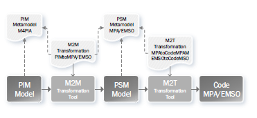 Figure 1: Development cycle using M4PIA
M4PIA infrastructure is built as support for the MDE
of equipment class definition, so that applications for operation, control, and simulation platforms for the petrochemical industry can be created. The proposed solution was implemented in the EMF (Eclipse Modeling Framework) tool [29], in Eclipse Oxygen environment. The first and fundamental element built is the M4PIA metamodel, a PIM metamodel that represents the entire domain of the desired applications to be created, independently of its implementation platform. Then the PSM metamodels were constructed, defining the specificities of each supported platform. Based on metamodels, it was defined the M2M transformations from PIM model to PSM models and, at last, the M2T transformations for the automatic source code generation from each PSM model.
3.1. M4PIA Metamodel
The identification and analysis of petrochemical industry applications allowed the definition of a set of generic elements, capable of being shared by a wide range of industrial automation systems. This set of elements are materialized by means of a metamodel named M4PIA. Our aim is that M4PIA metamodel can contribute substantially for the implementation of new systems from such application domain, targeting reusability and facilitating automatic code generation.
The developed M4PIA metamodel is presented here through a class diagram designed using the Eclipse Modeling Framework and its Ecore metamodel, similar to UML. The proposed class diagram is shown in Figure 2. The representation shows a set of classes, interfaces, and collaborations, with their respective relationships, expressing results of the structure and requirements analysis of the problem domain and its components. Model constraints were specified using OCL (Object Constraint Language). The main metamodel elements are detailed next.
An entity is defined as the most elementary unit of the proposed model. The Entity class is considered abstract and only provides a basic structure for the more specialized classes in the hierarchy. A Project is instantiated and can be composed of several Files. These can be imported as libraries, ImportedFile, or be an entity group to have their source code generated by the infrastructure, GeneratedFile.
An Equipment is a type of entity that can contain attributes and methods, defined as specific classes to reflect physical characteristics and functions performed by the equipment in a plant.
The abstract class Variable represents a logical variable and can be NonTyped or Typed. Typed variables can be EquipmentType or BasicType, more specifically Real, Integer, Boolean, or String.
The Method class is a Function specialization and has exclusive connection to an Equipment. The Function class represents a logical entity that can either represent a highlevel operation (in the physical domain of the plant) or a low-level (in the application domain). A function can have multiple Variable instances associated, acting as parameters or results, as well as may have a language and an associated code, which textually describes the instruction desired for the interpreter.
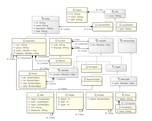 Figure 2: Elements of the proposed M4PIA metamodel
An equipment Attribute is a specific case of Variable which is allowed, through the relationships hierarchy, to assume a type that can be another Equipment. This aspect guarantees to the metamodel the ability to reproduce scenarios where there are natural recursions in relationships between equipment, i.e., an equipment or a machine that has other equipment as an attribute. For example, a specific type Compressor can be used as one of the attributes of a Compression System, both devices being instantiated by the Equipment class.
Furthermore in the Attribute context, there is a permission management for read or write operations, as highlighted in the Access class. New data types can be defined through the DeclaredType entity, based on basic types, and can be used as the basis for variables and attributes as well. For example, it is possible to declare a new type Positive Real and set a real type attribute Position of an equipment Valve based on the Positive Real type.
3.2. MPA and EMSO Metamodels
Given that the generic M4PIA metamodel was obtained through the analysis of the specific software platforms, the specific metamodels for each software are similar to the generic one and the main differences between them are further highlighted.
The PSM for MPA, or simply MPA metamodel, is depicted in Figure 3. The Component element corresponds to Entities in M4PIA. In addition to Equipment, the Class component can also be specified as PointClass, considered on the platform as a data type. Variable and Attribute classes are not abstract and must have an associated Type. Possible types are BasicType, point classes, and equipment.
MPA basic types instances are imported automatically at the beginning of each project, they are: Real, Integer, Logical, and Textual. Four instances of native MPA point classes are also imported: Real Point, Integer Point, Logical Point, and Textual Point, each with its attributes.
In the MPA platform, codes are not exclusive related with functions, classes and files can also be composed by Codes. File codes are used to import components of the DLL, declaring the available DLLFunctions and their DLLParameters.
The second PSM developed is the EMSO metamodel, which is presented in Figure 4. Since EMSO is a simulation platform, mathematical models of the equipment, or Devices, are instantiated through the Model class. Functions are always related to a model as Equations. In this specific domain, Variable is an Attribute specialization and represents the variable attributes of the models and Parameter the constant ones. Variables cannot assume a textual type, but textual parameters can be instantiated through a Switcher. Flowsheet entities with their Devices and Connections, parameter Estimation and process Optimization were not considered primordial for the equipment description domain and are not specified at this stage of the project.
3.3. M2M and M2T Transformations
For each PSM supported by M4PIA infrastructure it is necessary to define the respective transformations. Transformations can be either model-to-model (M2M) or model-totext (M2T). In M2M transformations the elements specified in the PIM model are mapped to elements from a specific PSM. M2M are implemented in our work using the Eclipse QVTo tool, an implementation of the standard
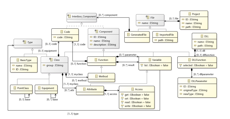 Figure 3: Elements of MPA metamodel
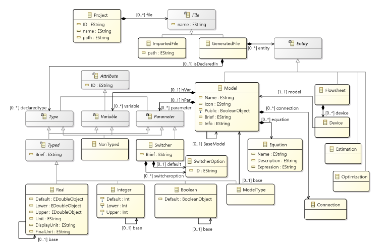 Figure 4: Elements of EMSO metamodel
OMG model transformation language QVTo (Operational Query/View/Transformation). The M2T transformations are developed specifically for each target platform. They are target in this work by using the Eclipse Acceleo tool for templates definitions and have as output the application source code ready to be used.
The explanation regarding each PSM metamodel provided in the previous section provide readers a good overview about the adopted M2M transformation rules, i.e., how the elements of the M4PIA metamodel (Fig. 2) map to the MPA metamodel (Fig. 3) and to the EMSO metamodel (Fig. 4). The M2T transformations are target in this work by using the Eclipse Acceleo tool for templates definitions and have as output the application source code ready to be used.
4. Evaluation Method
This section describes the evaluation method used to allow analyzing the completeness and applicability of the proposed infrastructure. Our goal is to capture the perception of M4PIA users in performing a characterization of the features associated with this MDE-based approach. By achieving this goal, it would allow us to understand whether the concepts introduced in M4PIA infrastructure really have potential in terms of technology, thus providing evidence of quality attributes associated with all the developed tools.
This evaluation, therefore, attempts an empirical study of type “feature analysis-experiment” [32], in a quantitative and qualitative experiment format. It allows providing evidences of suitability, very common for assessing tool support in computer science.
4.1. Context Selection
The context of this study is the academy, a first trial of invitro approach, with half of participants working in industry. The experiment captures the perceptions of individuals to measure the value of a technology in a real problem. It is applied with nine master students and two undergrad students from the Federal University of Pampa (Unipampa), all them with good knowledge on tool selection and software acquisition. This context configures a good sample, since students were introduced in the MDE theme, with desirable features from these tools. Therefore, it characterizes a good scenario to evaluate two main quality attributes for suitability that could be associated with the proposed tool support: completeness and applicability.
4.2. Experiment Design
No randomization and balancing: The subjects are not randomly placed into groups (not a randomized block design), so that only one design approach is performed by the same number of subjects. Thus, the goal is not to compare DSLs or code generators.
Blocking: The selected subjects for this quasiexperiment had different backgrounds in modeling systems, but no background in modeling petrochemical systems. Thus, to minimize the effect of eventual differences in experiences, the subjects received the same training. We also defined whether a subject is inexperienced or experienced, applying a survey, prior to the experiment, to qualify the subject background on the problem domain.
Instrumentation: It was provided a configured version of the Eclipse IDE with M4PIA plugins. The subjects installed this version in their notebooks in Windows or Linux. Then, we provided video tutorials in mp4 format, composed by: 1) A long duration video (75 minutes) depicting the proposed infrastructure, the needs and the proposed solution; 2) A second video (15 minutes) demonstrating how to use the Eclipse IDE, and 3) A third Video (25 minutes) demonstrating how to design a model using the proposed approach. Six other video-tutorials complement the other quantitative part of this experiment, focusing in evaluating specific design and codification tasks. However, they are irrelevant for the present evaluation, which focuses in presenting the feature analysis experiment.
4.3. Variables
Two sets of independent variables are used: (1) EMSO,
MPA, and M4PIA; (2) Academic Experience and Industrial Experience. Besides, two dependent variables are used: Completeness and Applicability.
4.4. Data Analysis
Applicability: a survey to measure the quality attributes from the experience along design and transformation tasks. Completeness: a coverage analysis of the main features considered important in MDE including the following.
4.4.1 Desirable Features from MDE Tools
Feature 1: Platform independence: Also known as PIM support [33], it evaluates the capacity to model the PIM application at a high abstract level.
Feature 2: Multiview representation: Also known as PSM support [33], it evaluates the capacity to automatically generate a PSM model for a chosen target platform.
Feature 3: Platform adherence: Also defined in [33], it states whether multiple target platforms are supported.
Feature 4: Evolution: Also known as Application evolution (Changeability) [33] [34], observes if model changes should be done in PIM level and implies new execution of transformations.
Feature 5: Interoperability: Relates to model import/export (tool interoperability) [33], observes the support for exporting models in XMI format.
Feature 6: Flexibility: From [33], accounts for the flexibility to change the transformation process and model refinements.
Feature 7: Correctness: From [33], accounts for model validation in order to check consistency with its metamodel.
Feature 8: Expressiveness: Also called completeness [33] [35], observe if all domain concepts are needed.
Feature 9: Traceability: From [33], accounts for models traceability.
Feature 10: Reverse engineering: From [33], accounts for Code-to-model and PSM-to-PIM transformations.
Feature 11: Built on standards: From [33], accounts for the use of standarized technologies.
Feature 12: Well defined concepts: Adopted from [34], observes if there are no contradictions between concepts of the models.
Feature 13: Code generation: Feature from [35], accounts for how complete is the generated application code.
4.4.2 Metrics
Metrics for estimating the completeness of the features:
CFx = 1 − ((44 − Cov)/44)
Where CFx is the completeness for a feature x, 44 is the maximum value rank for each feature, and Cov is the computed by:
Cov = (TD + PD + NA + PA + TA)
Where Cov is the coverage for a feature, as the sum of the following values posted by each respondent: TD is 0 (zero) and replaces the survey value for “Totally disagree”; PD is 1 (one) and replaces the survey value for “Partially disagree”; NA is 2 (two) and replaces the survey value for “Not agree or disagree”; PA is 3 (three) and replaces the survey value for “Partially agree”, and; TA is 4 (four) and replaces the survey value for “Totally agree”;
Thus, at the end of the quasi-experiment, a questionnaire was filled out in a Google Forms, were the participants should rate different criteria, where those for feature analysis are built on a five point Likert scale (0=worst, 4=best) for the analysis of the proposed infrastructure.
5. M4PIA Assessment
In order to evaluate the applicability of the proposed solution, this section presents the impressions noticed by the 11 users previously mentioned. Such impressions were collected after the users modeled a simplified Gas Compression System (GCS). The model was further used to generate the control software in the MPA tool and the simulation software in the EMSO tool. All related development, including the PIM model design and the transformation executions, was done within the Eclipse environment.
The simplified GCS consists of one surge tank (a knockout drum with a flaring valve), one output header, and two one-stage compressors. A stage of a compressor has one heat exchanger, one suction drum, one compression element, and one recycle valve. The output header has one exportation valve and two gas-lift output valves. Such system is illustrated in Figure 5. The present case study has 11 equipment, with a total of 36 attributes and 2 methods.
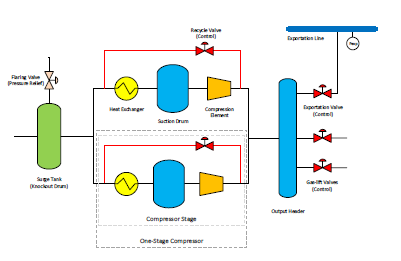 Figure 5: Simplified Gas Compression System
The work in the Eclipse tool can be summarized as follows. After creating a new project, the designer must create a PIM using the Eclipse tree structure. To illustrate how the designer interacts with Eclipse, Figure 6 shows the instantiation of three equipments from the GCS: Compression Element, Compressor, and Compression System. The former contains the following attributes: Flow, Suction/Discharge Pressures, and Suction/Discharge Temperatures. The latter has as attributes: Power, Surge Tank, Output Header, and a List of Compressors. It also has the method Calculate Power of the Compression System.
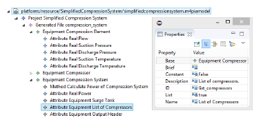 Figure 6: Illustration of the EMF tree structure
To model an equipment on both MPA and EMSO software platforms, the developers should seek out for generalization. For example, a compression system may have one or more compressors and a compressor may have one or more stages. Hierarchy is also highly desired, for example, a valve can be specialized in pressure relief or control valve, just as a tank can be specialized in surge tank or just a knockout drum. Given that in EMF the PIM is developed using a tree structure, as shown in Figure 6, the UML class diagram from Figure 7 was created to better illustrate the designed PIM.
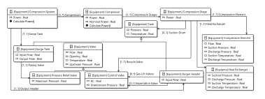 Figure 7: Class Diagram of the Simplified Gas Compression System PIM Model
After the PIM model development, the M2M transformations for MPA and EMSO platforms were performed. The PSM models were refined according to the specificity of each platform and it was possible to automatically generate the necessary source code to implement the compression system on the target platforms by applying the M2T transformations. In total, 245 effective lines of code were automatically generated for MPA and 117 for EMSO. One should recall that effective LOC means that comments and blank lines are not counted.
5.1. Preliminary Analysis
The system developed on this study can be considered small if compared to other existing applications, which can be five times bigger. In order to better illustrate the impact that the use of M4PIA can have on the development of the applications of this domain it is shown some data from a native MPA application example, which aims the detection and treatment of hydrate plug formation in gas pipelines of a floating production storage and offloading (FPSO). The numbers presented in Table 1 allow us to observe that an application with 50% more equipment classes (right on the table) can have twice the total amount of attributes and more than 12 times the number of methods. Observing the numbers regarding LOCs, the FPSO application is above 1K LOC. So it is not difficult to conclude that generating such code automatically – like M4PIA infrastructure does – can potentially save many working hours.
Table 1: Comparison of Domain Applications
| GCS | FPSO | |
| Class of Equipment | 11 | 17 |
| Total Amount of Attributes | 36 | 74 |
| Total Amount of Methods | 2 | 25 |
| Effective Lines of Code (LOC) – MPA | 245 | 1297 |
| Instantiated Equipment | 19 | 621 |
| Instantiated Control Points | 73 | 2428 |
5.2. Feature Analysis
In the following it is present data collected through a feature analysis, which allowed us to understand participants perceptions about the overall M4PIA infrastructure. The goal is to understand initial expectations of the overall approach introduced in the first video, so that their perception could help on the execution of the controlled experiment.
Figure 8 provides the answers to the analysis of Feature 1 – The approach allows to: model the application at platform independent level (PIM), at a high level of abstraction of the target problem used in the implementation (simulation, supervision, operation and control of industrial plants of the petrochemical industry. In this sense, nine from eleven students agree that this is an important feature provided in M4PIA infrastructure.
Figure 9 provides the answers to the analysis of Feature 2 – The approach allows: automatic generation of the platform-specific model (PSM) for the chosen target problem (simulation, supervision, operation and control of industrial plants in the petrochemical industry). Thus, nine from eleven students agree that this is an important feature provided by the infrastructure.
 Figure 8: Analysis of Feature 1: Platform independence
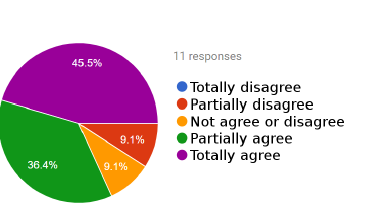 Figure 9: Analysis of Feature 2: Multiview representation
Figure 10 provides the answers to the analysis of Feature 3 – The approach allows: automatic generation of code for multiple target platforms. Seven participants agree that this is an important feature provided by the infrastructure, where five of them only partially agree. Thus, feature 3 should be planned for improvement.
 Figure 10: Analysis of Feature 3: Platform adherence
Figure 11 provides the answers to the analysis of Feature 4 – The approach supports the evolution of applications through model to model and model to code transformations. In this sense, nine from eleven students agree that this is an important feature provided by the M4PIA infrastructure. In fact, evolution is one of the greatest benefits promoted by MDE approaches for automated integration [14], and M4PIA is on a solid ground to allow this feature for their future users.
 Figure 11: Analysis of Feature 4: Evolution
Figure 12 provides the answers to the analysis of Feature 5 – The approach supports model interoperability. That is, it is evaluated whether these are exported and imported in a standard way, such as those provided by OMG. Seven agree that this is an important feature provided by the infrastructure, where five of them only partially agree. Three answers were uncertain, and this is because OMG supports lots of other standards not handled in M4PIA.
 Figure 12: Analysis of Feature 5: Interoperability
Figure 13 provides the answers to the analysis of Feature 6 – The approach supports flexibility to change the transformation process and model refinements. Eight respondents agree that this is an important feature that should be provided by the infrastructure. Three answers were also uncertain, and this is because they did not scaled the problem through the demonstration.
 Figure 13: Analysis of Feature 6: Flexibility
Figure 14 provides the answers to the analysis of Feature 7 – The approach supports the validation of the models to verify consistency with their respective metamodels. Eight respondents agree with that statement, concluding that M4PIA provides this as an important feature for designers. Consistency in design is an essential feature in a MDE-based process that needs the correct code generation. It can only be ensured with a rich set of OCL rules [36].
 Figure 14: Analysis of Feature 7: Correctness
Figure 15 provides the answers to the analysis of Feature 8 – The approach is expressive and allows to express all the concepts of the represented problem domain. Nine from eleven respondents agree that this is a design feature associated with M4PIA. Thus, since the ability of express domain concepts is a requirement for DSL development, we conclude that the provided metamodels satisfy the modeling needs of the presented context.
 Figure 15: Analysis of Feature 8: Expressiveness
Figure 16 provides the answers to the analysis of Feature 9 – The approach supports the traceability of models. Nine from eleven respondents agree that this is a design feature associated with M4PIA. Trace is promoted through model-to-model transformations and are used for configuration management issues [37].
 Figure 16: Analysis of Feature 9: Traceability
Figure 17 provides the answers to the analysis of Feature 10 – The approach supports reverse engineering from code to model. This statement was detected as an issue from the current version of M4PIA. first experimental trial. This feature is only implemented as a preliminary version of the infrastructure developed in ANTLr parser, not include in the provided Eclipse experimental package. In order to configure a reverse engineering into the Eclipse package, we are starting the development of reverse engineering using MODISCO. So the answers for this feature analysis were also confused.
 Figure 17: Analysis of Feature 10: Reverse engineering support.
Figure 18 provides the answers to the analysis of Feature 11 – The approach is heavily based on standards for building DSLs and model transformations. Nine from eleven respondents agree that this is an important feature associated with M4PIA. One of the answers reasoned that the adopted technologies is not a benefit.
 Figure 18: Analysis of Feature 11: Built on standards
Figure 19 provides the answers to the analysis of Feature
- – There are no contradictions between the concepts of models in the M4PIA infrastructure. Here only five agree that the metamodels are well characterized, while five are still confused and suggested that they would have a stronger position with a better characterization of the context from the Petrochemical industry.
 Figure 19: Analysis of Feature 12: Focused domain specific entities
Figure 20 provides the answers to the analysis of Feature
- – The complete application code can be generated. six from eleven respondents agree that this is an important feature associated with M4PIA. Almost half the respondents or disagree or did not have sufficient information to conclude about that.
 Figure 20: Analysis of Feature 13: Code generation
5.3. Final Remarks
Figure 21 presents the coverage analysis of the features after applying the metric. The highest possible score for each feature is 44. Figure 23 shows the dispersion bloxplot graph. Therefore, these graph demonstrates that M4PIA infrastructure is considered relevant for the stated problem.
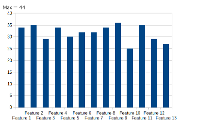 Figure 21: Coverage analysis of all the features
Finally, Table 2 presents the analysis of completeness of each analyzed feature. This data is also shown in Figure 22. The average of results from coverage is 72.73%, a good index suggesting the relevance to the MDE context. Thus, this suggests that we are on the way to achieve benefits reported by other MDE studies as well [14].
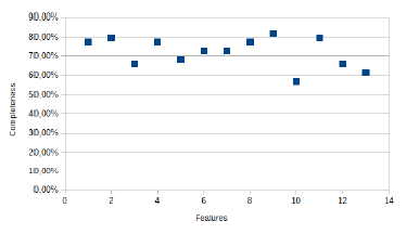 Figure 22: Completeness analysis of all the features.
5.4. Threats to Validity
As discussed by [32], studies of applicability using feature analysis experiment are usually target of the following
|
Table 2: Analysis of completeness after the feature analysis
|
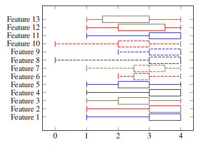 Figure 23: Boxplot of the analyzed features
threats to validity: 1) Benefits are difficult to quantify, 2) Benefits directly observable from the task output, 3) Relatively small learning time, and 4) Tool/method user population very varied. In the following, we present other threats conforming to [38].
5.4.1 Construct Validity
Feature analysis presents social threats to construct validity. In order to mitigate the Hypothesis guessing, before executing the experiment we: 1) presented the context of the problem; 2) presented the context of MDE tools; and 3) presented our goals, where we would evaluate their intuitiveness in using the M4PIA approach for each planned task along three different phases. These experimental tools were also important to mitigate the other two threats: Evaluation apprehension and Experimenter expectations. In order to mitigate the apprehension threat, an external executor for this quasi-experiment was used (the third author). This makes the study less biased, avoiding the interest in positive results, which could occur when the study is executed by the tool creators. The experiment executor also ensured the selection of subjects without any expectation about the evaluated tool, making clear their responsibility in feature analysis to rank M4PIA accordingly to the thirteen best MDE practices.
5.4.2 Internal Validity
This study was planned as a controlled experiment to be executed in three distinct phases: 1) the first one is to test the applicability of M4PIA; 2) the second one is the manual execution of the overall process, scoping design and codification tasks, performed without M4PIA; and 3) the last is the execution of the process with M4PIA. Along the execution of the first phase in the first trial, we observed that the internal validity threat called “mortality” would happen for the next phases due to the scarce available time from subjects. In order to mitigate this threat, and thus ensuring we would not loose subjects, we decided that participants could execute the experiment at home along three weeks. In this sense, they followed the video tutorials for execution of each requested task in a quasi-experiment rather than a fully controlled experiment, as initially planned. Therefore, in order to ensure the internal validity, the independent variable “time to accomplish each task” was not used.
5.4.3 External Validity
The results observed for feature analysis of M4PIA infrastructure are not generalized yet. For a such, we would need to repeat this study with, at least, three other subject profiles: 1) experts in physical plants presented on the development of simulation, control, and supervisory applications for the petrochemical industry; 2) experts both in physical plants and MDE; and 3) experts both in physical plants, MDE and software acquisition. Likewise, the threat “interaction of selection and treatment” was not mitigated, and will not gonna be while this experiment is not repeated with different subject profiles. Since our subjects are not experts in the problem domain, i.e. they are trainees in physical plants adopted by petrochemical industry, but they are experts in Software Engineering tool selection and software acquisition discipline, this study is also target of the threat “interaction of setting and treatment”. We mitigated this threat through nine video-tutorials, shared in the experimental package, which by the way are considered of high instructive quality.
5.4.4 Conclusion Validity
This study presents an associated threat, which is its low statistical power, as the evaluation presented was applied to only eleven participants. It happens that, for a feature analysis, the random heterogeneity of the subjects compensates the low statistical power, as it provides different perspectives when evaluating the tool. Likewise, the subjects present two distinct evaluators profiles: half working on companies as professional software engineers and half characterized as students, where two of them are finishing the undergraduate school in Software Engineering. Thus, our conclusions are moderated and drawn accordingly to the statistical power provided.
6. Conclusions and Future Works
The current paper presented M4PIA, an MDE solution that facilitates the design and development of equipment classes for simulation, control, and operation of applications devoted for the petrochemical industry. It contains three metamodels, which is a rich material in respect to formalizing the representation of the elements that constitute petrochemical plants and the related control structure. These metamodels, together with the developed model transformation engines, serve to provide automatic code generation.
The conducted evaluation showed that the majority of the 13 features considered important in the scope of MDE are properly covered by the proposed M4PIA. Solutions to improve those features that were not highly ranked, like reverse engineering, are already under development. Moreover, as future work it is possible to state that M4PIA should evolve towards allowing even non-programmers (like plant engineers/designers) to describe plant structures and thereby providing additional help to develop the required applications. Therefore, a graphical modeling language might be adopted.
Conflict of Interest
The authors declare no conflict of interest.
Acknowledgment
Firstly we thank Cenpes/ Petrobras for the finance support that made this work possible. Thanks are also given to: (i) Tecgraf/PUC-Rio Institute team for the outstanding support in respect to MPA-related issues; (ii) Prof. Rafael de Pelegrini Soares (UFRGS) for his support in respect to the EMSO platform; (iii) the students from UNIPAMPA/Alegrete that did not measured efforts to perform the proposed evaluation protocol.
- International Electrotechnical Commission, “Iec 61131: Programmable controllers – part 3: Programming languages,” standard, 2003.
- International Electrotechnical Commission, “Iec 61499: Function blocks standard,” standard, 2005.
- The International Society of Automation, “Isa 106: Procedure automation for continuous process operations,” standard, 2013.
- E. Satuf, S. F. Pinto, and B. Q. Dias, “Sistema autom´atico de alinhamento para a plataforma de rebombeio autˆonomo PRA-1,” in V Congresso Rio Automa¸c˜ao, (Rio de Janeiro, RJ, Brasil), Inst. Brasil.de Petroleo, G´as e Biocombust ́ ́ıveis – IBP, 2009.
- R. B. France and J. M. Bieman, “Multi-view software evolution: A UML-based framework for evolving object-oriented software,” in ICSM, pp. 386–395, 2001. https://10.1109/ICSM.2001.972751.
- M. V¨oelter and I. Groher, “Handling variability in model transformations and generators,” in Companion to OOPSLA 2007, pp. 1–8, ACM, 2007.
- P. Mohagheghi, Evaluating Software Development Methodologies Based on their Practices and Promises, pp. 14–35. Frontiers in Artificial Intelligence and Applications, 2008. https://doi.org/10.3233/978-1-58603-916-5-14.
- R. P. Soares and A. R. Secchi, “EMSO: A new environment for modelling,simulation and optimization,” in 13th European Symposium on Computer Aided Process Engineering, pp. 947–952, Elsevier Science Publishers, 2003. https://doi.org/10.1016/S1570-7946(03)80239-0.
- D. Batory, E. Latimer, and M. Azanza, “Teaching model driven engineering from a relational database perspective,” pp. 121–137, 2013. https://doi.org/10.1007/978-3-642-41533-3 8.
- V. Aranega, A. Etien, and S. Mosser, “Using feature model to build model transformation chains,” pp. 562–578, 2012.
https://doi.org/10.1007/978-3-642-33666-9 36. - R. S. P. Maciel, R. A. Gomes, A. P. F. Magalh˜aes, B. C. da Silva, and J. P. B. Queiroz, “Supporting model-driven development using a process-centered software engineering environment,”Autom. Softw. Eng., vol. 20, no. 3, pp. 427–461, 2013.
https://doi.org/10.1007/s10515-013-0124-0. - P. Mohagheghi, M. A. Fernandez, J. A. Martell, M. Fritzsche, and W. Gilani, “Mde adoption in industry: Challenges and success criteria,” vol. 5421, pp. 54–59, 2009. https://doi.org/10.1007/978-3-642-01648-6 6.
- J. Hutchinson, J. Whittle, M. Rouncefield, and S. Kristo_ersen, “Empirical assessment of mde in industry,” in 33rd International Conference on Software Engineering, ICSE ’11, pp. 471–480, 2011.
https://doi.org/10.1145/1985793.1985858. - P. Mohagheghi, W. Gilani, A. Stefanescu, M. A. Fernandez, B. Nordmoen, and M. Fritzsche, “Where does model-driven engineering help? experiences from three industrial cases.,” Software & Systems Modeling, vol. 12, pp. 619–639, july 2013. https://doi.org/10.1007/s10270- 011-0219-7.
- R. Capilla, J. Bosch, P. Trinidad, A. Ruiz-Cort´es, and M. Hinchey, “An overview of dynamic software product line architectures and techniques: Observations from research and industry,” Journal of Systems and Software, vol. 91, no. 0, pp. 3–23, 2014.
https://doi.org/10.1016/j.jss.2013.12.038. - R. Monteiro, G. Zimbrao, and J. Moreira de Souza, “Collaborative evolution process in mdarte: Exchanging solutions for information systems development among projects,” in Computer Supported Cooperative Work in Design (CSCWD), 2014 IEEE 18th International Conference on, pp. 569–574, May 2014.https://doi.org/10.1109/CSCWD.2014.6846907.
- M. Torchiano, F. Tomassetti, F. Ricca, A. Tiso, and G. Reggio, “Relevance, benefits, and problems of software modelling and model driven techniques-a survey in the italian industry,” J. Syst. Softw., vol. 86, pp. 2110–2126, aug 2013.
http://dx.doi.org/10.1016/j.jss.2013.03.084. - G. Liebel, N. Marko, M. Tichy, A. Leitner, and J. Hansson, “Assessing the state-of-practice of model-based engineering in the embedded systems domain,” pp. 166–182, 2014. https://doi.org/10.1007/978-3-319-11653-2 11.
- J. Whittle, J. Hutchinson, M. Rouncefield, B. Håkan, and H. Rogardt, “A taxonomy of tool-related issues a_ecting the adoption of modeldriven engineering,” Software & Systems Modeling, pp. 1–19, 2015.
http://dx.doi.org/10.1016/10.1007/s10270-015-0487-8. - P. Mohagheghi and V. Dehlen, Where Is the Proof? – A Review of Experiences from Applying MDE in Industry, pp. 432–443. Berlin, Heidelberg: Springer Berlin Heidelberg, 2008. https://doi.org/10.1007/978-3-540-69100-6 31.
- B. Selic, “On software platforms, their modelling with uml 2, and platform-independent design,” in 8th IEEE International Symposium on Object-Oriented Real-Time Distributed Computing, ISORC’05, pp. 15–21, 2005. https://doi.org/10.1109/ISORC.2005.40.
- L. Rose, E. Guerra, J. Lara, A. Etien, D. Kolovos, and R. Kolovos, “Genericity for model management operations,” Software & Systems Modeling, vol. 12, no. 1, pp. 201–219, 2013.
- L. B. Becker and C. E. Pereira, “SIMOO-RT-an object-oriented framework for the development of real-time industrial automation systems,” IEEE Transactions on Robotics and Automation, vol. 18, pp. 421–430, Aug 2002. https://doi.org/10.1109/TRA.2002.802933.
- K. C. Thramboulidis, “Using UML in control and automation: a model driven approach,” in Industrial Informatics, 2004. INDIN ’04. 2004 2nd IEEE International Conference on, pp. 587–593, June 2004.
https://10.1109/INDIN.2004.1417414. - S. M. Becker, T. Haase, B. Westfechtel, and J. Wilhelms, “Integration tools supporting cooperative development processes in chemical engineering,” in Proc. of Integrated Design and Process Technology (IDPT-2002), Pasadena, California, Citeseer, 2002.
- C. Vidal, C. Fern´andez-S´anchez, J. D´iaz, and J. P´erez, “A modeldriven engineering process for autonomic sensor-actuator networks,” International Journal of Distributed Sensor Networks, vol. 11, no. 3, p. 684892, 2015. https://doi.org/10.1155/2015/684892.
- D. H¨astbacka, T. Veps¨al¨ainen, and S. Kuikka, “Model-driven development of industrial process control applications,” Journal of Systems and Software, vol. 84, no. 7, pp. 1100–1113, 2011. https://doi.org/10.1016/j.jss.2011.01.063.
- V. Vyatkin, “Software engineering in industrial automation: State-of-the-art review,” IEEE Transactions on Industrial Informatics, vol. 9, no. 3, pp. 1234–1249, 2013.https://doi.org/10.1109/TII.2013.2258165.
- D. Steinberg, F. Budinsky, E. Merks, and M. Paternostro, EMF: Eclipse Modeling Framework. Pearson Education, Inc., 2 ed., 2008.
- “Acceleo mda generator,” 2013. Av. at http://www.acceleo.org.
- OMG, “Meta object facility version 2.0 query/view/transformation specification,” tech. rep., OMG, 2005.
- B. Kitchenham, S. Linkman, and D. Law, “Desmet: a methodology for evaluating software engineering methods and tools,” Computing Control Engineering Journal, vol. 8, pp. 120–126, June 1997.
- “An Evaluation of Compuware OptimalJ Professional Edition as an MDA Tool,” tech. rep., Department of Computer Science – The University of York and King’s College London, 2003.
- P. Mohagheghi, V. Dehlen, and T. Neple, “Definitions and approaches to model quality in model-based software development – A review of literature,” Information and Software Technology, vol. 51, no. 12, pp. 1646–1669, 2009. https://doi.org/10.1016/j.infsof.2009.04.004.
- C. F. Lange and M. R. Chaudron, “Managing model quality in UMLbased software development,” in Software Technology and Engineering Practice, 2005. 13th IEEE International Workshop on, pp. 7–16, IEEE, 2005. https://doi.org/10.1109/STEP.2005.16.
- P. Andersson and M. H¨ost, “Uml and systemc – a comparison and mapping rules for automatic code generation,” vol. 10, pp. 199–209, 2008. https://doi.org/10.1007/978-1-4020-8297-9 14.
- J. Vara, V. Bollati, A. Jim´enez, and E. Marcos, “Dealing with traceability in the mdd of model transformations,” Transactions on Software Engineering, vol. 40, no. 6, pp. 555–583, 2014. http://dx.doi.org/10.1109/TSE.2014.2316132.
- C. Wohlin, P. Runeson, M. H¨ost, M. Ohlsson, B. Regnell, and A. Wessl´en, Experimentation in Software Engineering. Springer, 2012.