
Signal-to-Quantization Noise Ratio of the Parallel Digital Ramp Analog-to-Digital Converter
Volume 4, Issue 4, Page No 169-173, 2019
Author’s Name: Constantine Andreas Pappasa)
View Affiliations
ECE, Stevens Institute of Technology, 07030, USA
a)Author to whom correspondence should be addressed. E-mail: cpappas@stevens.edu
Adv. Sci. Technol. Eng. Syst. J. 4(4), 169-173 (2019); ![]() DOI: 10.25046/aj040421
DOI: 10.25046/aj040421
Keywords: SQNR, PDR ADC, Nonuniform Sampling

Export Citations
This work presents a theoretical analysis of the Signal-to-Quantization Noise Ratio (SQNR) of the nonuniform Parallel Digital Ramp Pulse Position Modulator Analog-to-Digital Converter (PDR-ADC) architecture. The PDR-ADC partitions the amplitude axis into P non-overlapping partitions that sample the analog input at input signal driven instances. Samples are generated when the input signal crosses a digital ramp in a partition. The parallel digital ramps operate from a single clock. For sinusoidal signals, it is shown, for uniform partitions the SQNR can be increased be increasing the number of bits in the counter or by increasing the number of partitions. A geometric partitioning scheme is then proposed where, again for sinusoids, it is shown that this quantization rule has the e_ect of attempting to maintain the SQNR approximately constant. For geometric partitioning, it is shown that the largest SQNR is achieved when the geometric parameter, common ratio, equals two.
Received: 05 March 2019, Accepted: 15 June 2019, Published Online: 30 July 2019
1. Introduction
Many alternatives to Nyquist rate sampling systems have been proposed in the literature [1] – [8]. Of the various methods described, the nonuniform Level Crossing (LC) architectures appear to dominate the recent literature, [9] -[14]. In [15], the PDR-ADC was introduced and circuits to affect the desired response developed. A specific partitioning scheme based upon partitioning the signal amplitude axis as a geometric series was developed in terms of circuit parameters. In this communication, alternative methods to increase the SQNR of the PDR-ADC and a more general discussion of the geometric partitioning in terms of the geometric progression parameter, common ratio, are presented.
All uniform quantizers begin to lose resolution as the amplitude of the input signal decrease. To understand where information is lost in uniform quantizers, a brief review of uniform quantization is presented. Next, the SQNR of the PDR-ADC is obtained under the conditions of a uniform partitioning scheme. The SQNR for a geometric partitioning scheme with common ratio two is developed without regard to any specific circuit analysis. Lastly, the SQNR for arbitrary common ratio is presented, where is is shown that the maximum increase in SQNR for geometric partitioning is obtained for a common ratio equal to two.
2. Uniform Quantization
Figure 1 is a block diagram of an ideal, uniform, analog to digital converter. The switch represents an ideal sample and hold (S&H) operation (aperture effects are ignored), such that the output of the S&H is the ‘instantaneous’ analog value of the input, f(t). The quantization rule is represented by the Q block. Lastly, the encoder, E, converts the quantizer output into the corresponding digital word.
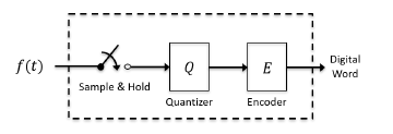 Figure 1: Ideal ADC
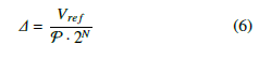
Let the number of bits in the digital word be, N, and let, Vref , be the analog reference voltage for the ADC, then, as is well known, that the quantization step size, ∆ is [15, 16]:
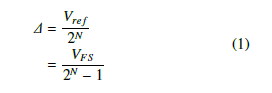 where VFS is the full scale voltage: VFS = Vref − ∆.
In uniform quantizers, the quantization noise power, PNQ , is well approximated by, [17, 18]:
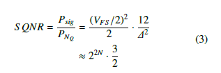
![]() The signal-to-quantization noise ratio (SQNR) is the ratio of the signal power, Psig, to the quantization noise power, PNQ . For a full scale sinusoid of the form, y =VFS sin(ωt), the S QNR is found to be:
The signal-to-quantization noise ratio (SQNR) is the ratio of the signal power, Psig, to the quantization noise power, PNQ . For a full scale sinusoid of the form, y =VFS sin(ωt), the S QNR is found to be:
 or in decibels, the familiar “rule of thumb” for sinusoids is obtained:
![]() Lastly, as is well known, when the amplitude of a sinusoidal signal decreases by a factor of 2, the signal power decreases by a factor of 4 and the ADC loses 1 bit of resolution. The S QNRdB, from 4, may be written as:
Lastly, as is well known, when the amplitude of a sinusoidal signal decreases by a factor of 2, the signal power decreases by a factor of 4 and the ADC loses 1 bit of resolution. The S QNRdB, from 4, may be written as:
 3. PDR: Uniform Partitions
Conceptually, the PDR-ADC may initially be regarded as a parallel arrangement of uniform quantizers as shown in Figure 2. Each quantizer, in Figure 2, is referenced independently and spans a different range of possible input signal values, thus partitioning the input signal axis [19, 15].
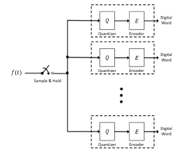 Figure 2: Parallel Quantization
In such an arrangement, if P is the number of partitions, and if each quantizer contains the same number of quantization levels, L, where L = 2N, and if each quantizer Vref has a dynamic range, so that together the P partitions P span Vref , then the quantization step size is given by:
 Such a parallel uniform partitioning scheme is illustrated in Figure 3 for a system with 4 partitions with 4 levels per partition.
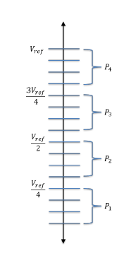 Figure 3: Parallel Uniform Partitioning
Equation (6) yields the same quantization step size as a single ADC with L = P · 2N levels, operating from the same
The PDR-ADC, however, operates from a single N bit digital counter, that generates 2N counts, that are scaled and shifted to generate the required number of partitions [15]. Consequently, if a single digital ramp ADC, operating with clock rate, TCLK, were required to span the same dynamic range, Vref , this single digital ramp would take P · 2N · TCLK seconds. The PDR-ADC however, spans the same dynamic range in 2
N · TCLK seconds, a 1 times improvement.
For a PDR-ADC, governed by (6), excited by a full scale VFS sinusoid of the form, y =sin(ωt), the S QNR is found 2 to be:
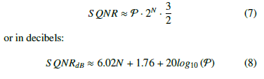 Equation (8) states, in the PDR-ADC, with each partition operating with the identical, uniform, step size, ∆, the signal-to-quantization noise may be increased in the usual way by increasing the number of bits used in the counter, N, and/or by increasing the number of partitions, P.
For example, the identical S QNR performance of a single, 16 bit ADC can be achieved with a PDR-ADC designed with, P = 8 partitions, operating with a 13 bit counter. Additionally, in this case, the PDR only counts to 8192, whereas a single digital ramp ADC would be required to count the full 65536 counts.
Additionally, in the PDR-ADC, the counter is not required to count, to a count value that is a power of 2. The same performance as described can be matched, approximately, from a PDR-ADC designed with P = 10 partitions and a counter that counts to 6554, thereby further decreasing the total time required to span the full dynamic range. A practical design constraint is that the number of partitions be even, so that the dynamic range of the PDR-DAC is symmetric about zero Volts.
4. PDR: Geometric Partitioning
In this section, the general behavior of the PDR-ADC with a geometric partitioning scheme of the amplitude axis, as illustrated in Figure 4, is presented without reference to circuit analysis[1]. For clarity, Figure 4 shows the essence of the geometric partitioning with a system of 4 partitions with 4 levels per partition. In the figure, the reference voltage of the entire system is equated to the maximum of the geometric sum, which is designated, 15Vx, for the yet to be determined voltage, Vx.
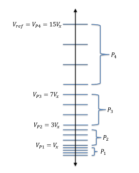 Figure 4: Parallel Geometric Partitioning
The mth reference voltage, VPm for each partition is related as a geometric series, and is obtained from:
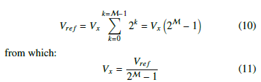
 Let M to be the maximum partition number, then, from the system reference voltage, Vref , the voltage Vx may be found from:
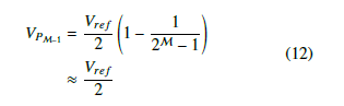
 The ratio of the nth term of a geometric progression to th + 1 term is, 1, where r is the common ratio, as is well known. If the common ratio is, r = 2, then as the number of partitions increases, the second to last partition is Vref referenced to a value that approaches 2 . In the case under consideration, the M − 1 partition is referenced from:
 4.1. Geometric SQNR
In the PDR-ADC, for any adjacent partitions, the ratio of the quantization step sizes is the common ratio, which may be written as:
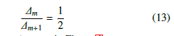 where this behavior can be seen in Figure 4.
From (2) and (13), it is seen, in the PDR-ADC, with common ratio, r = 2, the quantization noise power of adjacent partitions may be written as:
![]() In a PDR-ADC, with geometric partitioning, the quantization noise power decreases by a factor of 4 when transitioning from a higher partition to a lower partition.
In a PDR-ADC, with geometric partitioning, the quantization noise power decreases by a factor of 4 when transitioning from a higher partition to a lower partition.
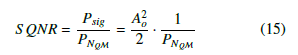
Let a full scale sinusoid of the for, y = Aosin(ωt), be input to the PDR-ADC, the SQNR is of the form:
 Now, suppose the input signal amplitude decreases by a Ao factor of 2 and let y = sin(ωt) be input to the PDR-ADC,2 the SQNR is given by:
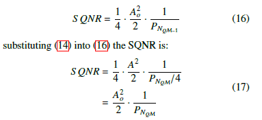 Equation (17) states, in the PDR-ADC, with a geometric partitioning, the signal-to-quantization noise attempts to remain approximately constant.
4.2. Constant SQNR
The constant value that the SQNR attempts to maintain can be obtained in terms of uniform ADC parameters with the aid of Figure 5. Figure 5 shows, on the left hand side, the uniform levels and the quantization step size for an 4 bit
(16 Levels) uniform ADC with dynamic range, VFS . The right hand side of Figure 5 shows the geometric partitioning for the same dynamic range. In the detail of Figure 5, the quantization step size of the largest partition is shown for a 4 bit counter that produces the same number of quatization levels (16 Levels) as the uniform quantizer shown on the left.
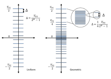 Figure 5: Constant Quantization Step Size
From (12), the dynamic range of the largest partition always approaches of the maximum voltage value, assuming a sufficient number of partitions. In the present case under consideration, as seen in Figure 5, this dynamic range is, . Consequently, when this range is divided by 4 2N levels, the largest quantization step size of a PDR-ADC with geometric partitioning is:
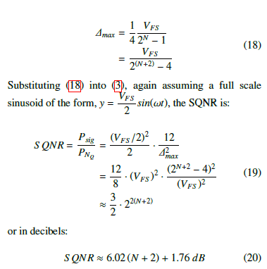
Equation (20) states, for a full scale sinusoidal input, a
PDR-ADC with geometric partitioning, operating from an N bit counter, gains 2 bits or resolution.
When the results of (20), (14) and (5) are taken together,
for a PDR-ADC with geometric partitioning, operating from an N bit counter, the following behavior is deduced:
- From (20): The PDR-ADC behaves as a system with N+2 bits.
- From (5): When the signal amplitude drops by a factor of 2, the signal power drops by a factor of 4 and the system loses 1 bit of resolution.
- From (14): When the signal amplitude drops by a factor of 2, the quantization noise power drops by a factor of 4, and the system gains 1 bit of resolution, and the system continues to behave as a system with N + 2 bits of resolution.
With geometric partitioning, the PDR data converter attempts to maintain the signal-to-quantization noise ratio approximately constant.
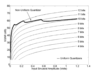 Figure 6: Approximately Constant SQNR from Geometric Partitioning
In Figure 6, the SQNR for the geometric partitioning, with common ratio r = 2, is shown as a function of input signal amplitude. The full scale voltage was, VFS = 2.4 Volts and the system was driven with a sinusoid of the form, y = Aosin(ωt), where Ao was varied from 1.2 Volts to approximately 1mV. The PDR was modeled with P = 8 partitions with an N = 8 bit counter.
For reference comparison, the SQNR for several uniform quantizers are also plotted in Figure 6. It is seen that the system performance is approximately equivalent to a system with N = 10 bits of resolution and that the system attempts to maintain this performance against variations in the peak signal amplitude. The peaking in the non-uniform quantizer are the locations where input signal voltage amplitude transitions from one partition to the adjacent partition.
5. Common Ratio and SQNR
Let the maximum voltage of the data converter be, , then, 2 for any value of the common ratio, r, the maximum value VFS of the next lower partition always approaches, , using a 2r
geometric partitioning scheme. Consequently, the dynamic range of the largest (outer) partition, M, is approximately:
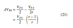 Assuming that this voltage is spanned by an N bit counter, and if driven by a sinusoid, the SQNR becomes:
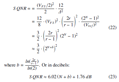 In 23, as the common ratio, r → ∞, b → 1, and the system only gains 1 bit of resolution. Alternatively, as r → 2, its minimum possible value, b → 2, and the system gains 2 bits of resolution. It is seen, in the PDR with geometric partitioning, the largest increase in the effective number of bits occurs with the common ratio, r = 2.
6. Conclusion
The signal-to-quantization noise (SQNR) of the parallel digital ramp analog to digital (PDR-ADC) has been formulated using a more general analysis using the common ratio of a geometric series. It was shown that for all values of the common ratio, using a geometric partitioning scheme, the maximum possible increase in the SQNR is achieved when the common ratio, r = 2, and the effective increase in the number of bits of resolution provided by an N bit counter is accordingly, 2. It was shown that with geometric partitioning, the PDR-ADC attempts to maintain the SQNR approximately constant. Additionally, it was shown, using a uniform partitioning scheme provides more flexibility in the effective increase in the counters effective resolution with a trade off in the number of partitions, though in this case, the SQNR does not remain approximately constant.
Conflict of Interest
The author declares no conflict of interest.[1] A circuit realization of the geometric behavior can be found in [15].
- J. Mark, T. Todd, “A Nonuniform Sampling Approach to Data Compression” IEEE T COMMUN, 29(1), 24–32, 1981.https://doi.org/10.1109/TCOM.1981.1094872
- N. Sayiner, H. Sorensen, T. Viswanathan, “A Level-Crossing Sampling Scheme for A/D Conversion” IEEE T CIRCUITS SYST, 43(4), 335–339, 1996. https://doi.org/10.1109/82.488288
- E. Allier, J, Goulier, G. Sicard, A. Dezzani, E. Andre, M. Renaudin, “A 120nm Low Power Asynchronous ADC” in ISLPED ’05. Proceedings of the 2005 International Symposium on Low Power Electronics and Design, San Diego USA, 2005. https://doi.org/10.1145/1077603.1077619
- T. Wang, D. Wang, P. Hurst, B. Levey, S. Lewis, “A Level-Crossing Analog-to-Digital Converter with Triangular Dither” IEEE T CIRCUITS SYST, 56(9), 2089–2099, 2009. https://doi.org/10.1109/TCSI.2008.2011586
- S. Naraghi, “Time-Based Analog to Digital Converters”, Ph.D Thesis, University of Michigan, 2009.
- P. Maechler, N. Felber, A. Burg, “Random Sampling ADC for Sparse Spectrum Sensing” in 2011 19th European Signal Processing Conference, Barcelona Spain, 2011.
- S. Becker, “Practical Compressed Sensing: Modern Data Acquisition and Signal Processing”, Ph.D Thesis, California Institute of Technology, 2011.
- M. Wakin, S. Becker, E. Nakamura, M. Grant, E. Sovero, D. Ching, J. Yoo, J. Romberg, A. Emami-Neyestanak, E. Candes, “A Nonunifom Sampler for Wideband Spectrally-Sparse Environments” IEEE J EM SEL TOP C, 2(3), 516–529, 2012. https://doi.org/10.1109/JETCAS.2012.2214635
- R. Siddharth, Y. Nithin Kumar, M. Vasantha, Edoardo Bonizzoni, “A Low-Power Auxiliary Circuit for Level-Crossing ADCs in IoT-Sensor Applications” 2018 IEEE International Symposium on Circuits and Systems (ISCAS), Florence, Italy, May 2018. https://doi.org/10.1109/ISCAS.2018.8351368
- Marco A. Gurrola-Navarro, “Frequency-Domain Interpolation for Simultaneous Periodic Nonunifom Samples” in 2018 IEEE 9th Latin American Symposium on Circuits and Systems (LASCAS), Puerto Vallarta Mexico,, 2018. https://doi.org/10.1109/LASCAS.2018.8399937
- T. Wu, C. Ho, M. Chen, “A Flash-Based Non-Uniform Sampling ADC With Hybrid Quantization Enabling Digital Anti-Aliasing Filter” IEEE J Solid-State Circuits, 5(9), 2335 – 2349, 2017. https://doi.org/10.1109/JSSC.2017.2718671
- S. Qaisar, M. Ben-Romdhane, O. Anwar, MTlili, A. Maalej, F. Rivet, C. Rebai, D. Dallet, “Time-domain characterization of a wireless ECG system event driven A/D converter” in 2017 IEEE International Instrumentation and Measurement Technology Conference (I2MTC), Turin Italy, 2017. https://doi.org/10.1109/I2MTC.2017.7969682
- M. Malmirchegini, M. Kafashan, M. Ghassemian, F. Marvasti, “Nonuniform sampling based on an adaptive level-crossing scheme” IET SIGNAL PROCESS, 9(6), 484–490, 2015. https://doi.org/10.1049/ietspr. 2014.0170
- S. Qaisar, R. Yahiaoui, T. Gharbi, “An E_cient Signal Acquisition with an Adaptive Rate A/D Conversion” 2013 IEEE International Conference on Circuits and Systems (ICCAS), Kuala Lumpur, Malaysia , 2013. https://doi.org/10.1109/CircuitsAndSystems.2013.6671611
- R. Baker, H. Li, and D. Boyce, CMOS Circuit Design, Layout and Simulation, IEEE Press Series on Microelectronic Systems, Wiley Interscience, 1998.
- W.R. Bennett, “Spectra of Quantized Signals” Bell Sys. Tech. Journal, 27(3), 446–472, 1948. https://doi.org/10.1002/j.1538-7305.1948.tb01340.x
- R. Gray, D. Neuho_ “Quantization” IEEE T INFORM THEORY, 44(6), 2325–2383, 1998. https://doi.org/10.1109/18.720541
- C. Pappas, “A New Non-Uniform ADC: Parallel Digital Ramp Pulse Position Modulator” in 2018 IEEE Canadian Conference on Electrical & Computer Engineering (CCECE), Quebec