
Experimental Evaluation of Transmission between Two XBee Modules Using Radio-over-Fiber Technique
Volume 4, Issue 4, Page No 128-132, 2019
Author’s Name: Luis Alejandro González Mondragón1, Leidy Johana Quintero Rodríguez1, Ana Gabriela Correa Mena1, Jorge Rodríguez Asomoza2, Alejandro García Juárez3, Ignacio Enrique Zaldívar Huerta1,a)
View Affiliations
1Instituto Nacional de Astrofísica, Óptica y Electrónica, Depto. de Electrónica, Calle Luis Enrique Erro No. 1, Tonantzintla, Puebla, México, 72840
2Universidad de las Américas, Depto. de Ing. Electrónica, Ex-hacienda Sta. Catarina Mártir, Cholula, Puebla C.P. 72820, México
3Universidad de Sonora, Depto. de Investigación en Física, Blvd. Luis Encinas y Rosales S/N, Hermosillo, Sonora, 83000, México.
a)Author to whom correspondence should be addressed. E-mail: zaldivar@inaoep.mx
Adv. Sci. Technol. Eng. Syst. J. 4(4), 128-132 (2019); ![]() DOI: 10.25046/aj040415
DOI: 10.25046/aj040415
Keywords: Microwave signals, Radio over fiber, Optical communications, XBee

Export Citations
An experimental transmission between two XBee modules using Radio over Fiber technique is demonstrated. Data issued from an XBee module coded on a wireless microwave carrier at 2.44GHz is transmitted through an optical link of 25.24 km. The optical transmission is based on an external modulation scheme over a dispersive channel. Frequency response of the external modulation scheme is determined by simulation and experimentally. In particular, the chromatic dispersion of the optical fiber associated to its length allow the generation of a pass-band filter whose bandwidth is used to code the RF signal. The recovered RF signal exhibits a SNR of 27dB. Obtained results allow proposing this RoF scheme as a good contender for data transmission.
Received: 05 April 2019, Accepted: 04 July 2019, Published Online: 17 July 2019
1. Introduction
This paper is an extension of the work originally presented at the 15th International Conference on Electrical Engineering, Computing Science and Automatic Control [1]. Now, the main contribution of this extended work resides in the fact that we are describing the mathematical procedure that allows determining the frequency response of the electro-optical system used for the transmission. Besides, the theoretical behavior of the optical communication system is validated by simulations. This work is situated on the field of Radio-over-Fiber (RoF), a technique that allows joining radio frequency and electro-optic methods. RoF emerges as a promising solution to fulfill the capacity and mobility of access networks providing high data rate, high capacity and a mobility proposal to transmit information [2-4]. Given that the transmission of information is via light through optical fibers, it is evident that its inherent advantages are exploited, such as low losses, immunity to electromagnetic interference and especially the huge bandwidth available. Figure 1 shows a basic RoF scheme composed by a RF-to-Optical stage, an optical link and an Optical-to-RF stage. The RF signal modulates the light (either directly or externally). The modulated light travels across the optical channel. Finally, the light is turned into its electrical form where it can be radiated by an antenna providing wireless coverage in zones of difficult connection such as shopping centers and subterraneous places [5].
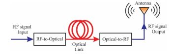 Figure 1. Basic diagram of a RoF system
RoF technology is a candidate that aims to alleviate the bandwidth restrictions for 5G Mobile, delivering wireless data signals via optical fiber channels. [6]. Thus, RoF allows supporting secure, cost-effective coverage as well as excellent capacity mobile-wireless access for oncoming services. Some drawbacks inherent to RoF are due to the distortion and noise derived by the non-linear features of the components employed in the optical network as the optical sources, the chromatic dispersion and photodetectors. For this reason, to mitigate sources of noise and misstatement, intensity-modulation-direct-detection is advisable [7]. In this regard, we propose and experimentally demonstrate a RoF scheme using an optical communication system in the modality of external modulation for the transmission and distribution of a RF-signal. Furthermore, it is demonstrated that the chromatic dispersion (considered as a drawback in this type of systems), is used in an advantageous manner to the generation of notch filters. On the other side, it is known that an XBee is an electronic device whose operation is based on the network transport protocol IEEE 802.15.4, it is able to generate wireless paths to establish communication between devices (http://xbee.cl/que-es-xbee, https://www.digi.com/products/xbee-rf-solutions/xctu-software/xctu). In this sense, XBee modules that use the ZigBee protocol find applications in RoF networks [8, 9]. In this experimental proposal, a wireless signal delivered by an XBee module is used as test signal. A baseband modulation Gaussian Frequency Shift Keying (GFSK) signal at 2.44GHZ is generated by an XBee. This electrical signal modulates an intensity electro-optic modulator. This work is structured as follows. In Section 2, is given the principle of operation of the optical communication system at external modulation and also numerical simulations are presented. In Section 3, experimental set-up of the RoF is described. At the end, a short conclusion is given in Section 4.
2. Principle of Operation
Figure 2 depicts the block diagram the optical communication system in the modality of external modulation used in this work. Basically, it is constituted by a single-mode laser diode as optical source, a Mach Zhender-Intensity Modulator (MZ-IM), a Single Mode-Standard Fiber (SM-SF), as well as a Photodiode (PD).
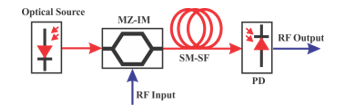 Figure 2. Block diagram of the model used
In the following, a full mathematical analysis explaining the behavior of the model is given. In order to exploit the chromatic dispersion exhibited by the SM-SF, it is necessary to assume that the single-mode laser diode emits at 1550nm. It is demonstrated that the chromatic dispersion (D) and the length (L) of the optical link play an important role that allow the system to act as photonic notch filter.
Mathematically, the optical spectrum of a single-mode laser diode (for example a DFB) can be modeled by a Gaussian envelope centered at an angular frequency as [10]
![]() where is the maximum power emission and is the Full Width at Half Maximum of the spectrum that can be expressed in terms of . Eq. (1) can be simplified, defining and , resulting in
where is the maximum power emission and is the Full Width at Half Maximum of the spectrum that can be expressed in terms of . Eq. (1) can be simplified, defining and , resulting in
![]() The Fourier Transform (FT) of Eq. (2) is the spectral density of the optical source, thus
The Fourier Transform (FT) of Eq. (2) is the spectral density of the optical source, thus
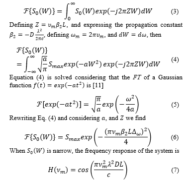 The squared of the modulation frequency makes the system behave like a non-periodic notch filter.
The notch frequencies , for which Eq. (7) becomes zero, are determined by
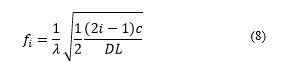 where is the central wavelength in nm, is in ps/nm·km, is speed of light in nm/s, and is the length of the optical link in km.
Equation (7) is numerically evaluated by using MATLAB for the frequency range 0-25GHz, considering: λ=1550nm, c=2.9979×10¹⁷nm/seg, L=25.24km, D=15.81ps/nm×km.
Moreover, substituting λ, c, L, and D in Eq. (8), the first and second notch frequency values are f1=12.50GHz and f2=21.65GHz, respectively.
Figure 3 shows the result of this numerical evaluation. The result of this evaluation is corroborated by a block level simulation using VPIphotonics softwareâ (http://www.vpiphotonics.com/index.php), and plotted on the same graph. This software is provided with a full library of electro-optics components whose properties can be easily manipulated, therefore, the degree of reliability for the results is high.
From this graph, it is clearly appreciable that the separation between consecutive notches is not constant and decreases as the frequency increases. The bandwidth at -3dB for the low-pass band and for the first lobe (band-pass) are in the order of GHz. The common point between both curves is their tendency. Note that both curves converge to the values of 12.50GHz and 21.65GHz as stablished by Eq. (8). The justification to use 25km is because the current transmission lengths are designed to meet 20 km, as is determined by an international standard [12].
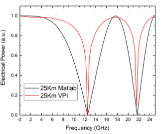 Figure 3. Simulated frequency response using MATLAB and VPI photonics software.
3. Experimental Results
Initially, a test communication between two XBee devices is carried out. Later, a characterization of the optical communication system is done. Finally, the performance of the system composed by a couple of XBee modules over a RoF link is accomplished.
3.1 Test of the XBee devices
XBee is a trademark of radio devices capable of supporting communication protocols as ZigBee, 802.15.4, and Wi-Fi, among others [9]. Figure 4 depicts an XBee network. One module plays the role of Coordinator whereas the other of an End Device.
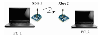 Figure 4. Network generated by using two XBee modules.
The Coordinator handles out addresses and manages the network The End Device is responsible for joining existing networks, transmitting and receiving information. In this work, two XBee modules (XBee-PRO model ZNet 2.5 OEM, indoor range 100m, operating frequency 2.4GHz, transmit power output 18dBm) are used. Both devices are provided with an omnidirectional antenna (Gain 2.15dBi, frequency range from 2.4 to 2.4835GHz) and an USB adapter (Sparkfun XBee Explorer Dongle) that allows the connection via serial communication. The communication between these devices is achieved by using the platform XCTU. Figure 5 shows this interface (https://www.digi.com/products/xbee-rf-solutions/xctu-software/xctu). Data to be transmitted by PC_1 (Coordinator) are coded at the frequency of 2.44GHz and then radiated via an antenna and decoded by PC_2 (End Device).
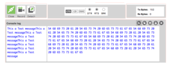 Figure 5. Screenshot showing the interface to control the Coordinator.
Figure 6 shows the spectrum of the emitted radio frequency signal at 2.44GHz measured by an Electrical Signal Analyzer (ESA) exhibiting a SNR value of 55dB. The baseband data is coded within the side lobes.
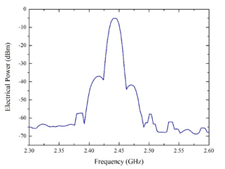 Figure 6. Electrical spectrum corresponding to the Coordinator
3.2 Experimental Frequency Response
Figure 7 illustrates the experimental bench used in this work. It is well known that the use of multimode optical fibers is reserved for short distances, such as in local area networks. Because, we are interested to emulate a FTTH-PON, whose typical length is in the order of 20km [12], thus the use of single-mode optical fiber is mandatory, due to its characteristics of extremely low-losses. Furthermore, most of commercial electro-optical devices (optical sources, optical modulators, photodetectors, etc.) operating at the commercial wavelengths of 1300 and 1550 nm, are supplied with this type of fiber. From the comments above described, SM-SF is used in this experiment. In the next sub-section, a detailed description of the optical communication system is given.
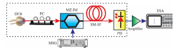 Figure 7. Optical communication system externally modulated
First, the optical spectrum of a DFB (NX8508-55, Side Mode Suppression Ratio SMSR=40dB, linewidth 0.1nm) is recorded by means of an Optical Spectrum Analyzer. According to the datasheet, this optical source has its own internal optical isolator to avoid reflections, therefore a good optical stability is guaranteed. Figure 8 shows the optical spectrum for an operation current of 20mA exhibiting a central wavelength l0=1553.5nm. The shape of the optical spectrum corresponds to Eq. (1).
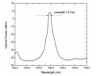 Figure 8. Optical spectrum of the DFB laser source used
Once the characteristics of the optical source are known, the light generated by the DFB is modulated via the electro-optic MZ-IM (insertion loss of 2.7dB, BW-20GHz, operating wavelength 1530-1580 nm, Vπ=7.5 V). The Polarization Controller (PC) device allows optimizing the optical power level at the output of the modulator. The RF signal used to modulate the light is provided by a Microwave Signal Generator (MSG) through a sweep in frequency range of 0.01-13 GHz at a power of 0 dBm. The modulated beam is injected to a reel of SM-SF (D=15.81ps/nm·km @ 1550nm, a=0.22dB/km, L=25.24 km). The light that emerges of the optical fiber is turned to its corresponding electrical signal by the PD (Miteq, BW-13GHz, Responsivity=0.9Amp/Watt). This signal is submitted to a process of amplification (Minicircuits, ZVA-183-S+ Ultra-Wideband Amplifier, 0.7-18GHz, Gain 26dB) and finally visualized in the screen of the ESA. Figure 9 corresponds to the measured frequency response where the simulation curves have been superimposed. Since the frequency emitted by the XBee Module is at 2.44GHz, the low-pass band will be used to code the transmission of the RF signal.
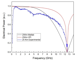 Figure 9. Comparison between simulated and experimental results
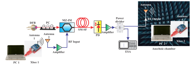 Figure 10. Experimental scheme assembled to test the RoF XBee transmission system
From this graph, it is noticeable that the response is restricted by the BW of the PD.
3.3 Experimental RoF Transmission
Figure 10 shows the test bench for carry out the transmission of the signal issued from the XBee module. The main difference to the scheme shown in Fig. 7 is that now the MSG is replaced by the coordinator module connected to PC_1 generating the information to be sent (an electrical signal at 2.44GHz at -6dBm) that is emitted from Antenna 1. Antenna 2 receives this signal which is amplified and launched to the RF port of the MZ-IM to modulate the optical signal. The modulated light is injected to the SM-SF. At the end of the link, the modulated light is converted into electric signal by the PD. Subsequently, amplified and separated by a power divider. A percentage of the recovered signal is evaluated by the ESA and the remainder is connected to the Antenna 3 where is emitted. An anechoic chamber is used to guarantee isolation between the signals emitted by antennas 1 and 3. Lastly, antenna 4 captures the signal to be handled by the second XBee module coupled to computer number 2 (PC 2), recovering in this manner the original transmitted message. Figure 11 corresponds to the measured electrical spectrum corresponding to the recovered signal with a SNR of 27dB.
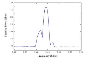 Figure 11. Recovered spectrum corresponding to the output of the system
4. Conclusion
In this work, we have experimentally demonstrated an efficient communication between two XBee modules using the RoF technique. The optical transmission was carried out by using an external modulation scheme. A full mathematical analysis explaining the principle of operation of an optical communication system was given. The relationship that allows determining the frequency response of the optical communication system was evaluated by a numerical simulation achieved in Matlab. Later, a block level simulation of the optical system was carried out by using VPIphotonics software corroborating the previous results. One thing to keep in mind is that the usage of an optical source whose central wavelength is 1310nm associated with SMSF allows the cancellation of the chromatic dispersion effect [12]. However, in this work, we have used a DFB laser whose central wavelength is around 1550nm and SM-SF; thus, the chromatic dispersion value was considerable. This effect, as well as, the length of the optical link has an important role to determine the electrical bandwidth of the system as it was evident in Eq. (7) and Eq. (8). The frequency response was composed by a low-pass band as well as a series of bandpass or notches. In particular, the first lobe was used for the transmission of a wireless signal of 2.44GHz issued by the XBee module. Optical transmission was successfully achieved through an optical link of 25.24Km. The recovered RF signal exhibits a SNR of 27dB. Considering that the electrical bandwidth can be tailored in function of the length of the optical link, it is possible to assure the possibility to accommodate future services distributed by means of RoF schemes using a larger bandwidth. Furthermore, another interesting feature of this RoF system is that, at the end of the link, data can be distributed by antennas to several customers. Direct and external modulation can be used to implement a D-RoF system in our case we have opted for external modulation using a Mach Zehnder modulator (MZM) to modulate a DFB laser in order to generate a simpler configuration [13]. As future work, we propose the use of a VCSEL as optical source in order to benefit of its properties as threshold currents of very few mA and facilitate the coupling with optical fibers [14].
Acknowledgments
- A. González-Mondragón, L. J. Quintero-Rodríguez, and A. G. Correa-Mena, wish to thank the CONACyT for the student scholarships number 553921, 465594 and 335148, respectively.
- L. A. González-Mondragón, L. J. Quintero-Rodríguez, A. G. Correa-Mena, J. Rodríguez-Asomoza, A. García Juárez, I. E. Zaldívar-Huerta, “Performance Evaluation of Transmission Between Two Wireless Devices Based on Radio-over-Fiber Technology”, in 2018 15th International Conference on Electrical Engineering, Computing Science and Automatic Control (CCE), Mexico City , MX, 2018. https://doi.org/10.1109/ICEEE.2018.8533916
- A. M. Zin, M. S. Bongsu, S. M. Idrus, and N. Zulkifli, “An overview of Radio-over-Fiber Network Technology”, in 1st International Conference on Photonics 2010 (ICP 2010), Langkawi, Malaysia, 2010. https://doi.org/10.1109/ICP.2010.5604429
- A. K. Vyas, N. Agrawal, “Radio over Fiber: Future Technology of Communication”, International Journal of Emerging Trends & Technology in Computer Science, 1(2), 233-237, 2012.
- J. Beas, G. Castañon, I. Aldaya, A. Aragón-Zavala and G. Campuzano, “Millimeter-Wave Frequency Radio over Fiber Systems: A Survey”, IEEE Communications Surveys Tutorials, 15(4), 1593-1619, 2013 https://doi.org/10.1109/SURV.2013.013013.00135
- S. Kaur, M. Srivastava, K. Singh Bhatia, “Radio over Fiber Technology–A Review,” International Conference of Technology, Management and Social Sciences, Special Issue ICTMS-15, 85-89, 2015.
- D. Apostolopoulos, G. Giannoulis, N. Argyris, N. lliadis, K. Kanta, and H. Avramopoulos, “Analog Radio-over Fiber Solutions in Support of 5G”, in 2018 International Conference on Optical Network Design and Modeling (ONDM), Dublin, Ireland ,2018. https://doi.org/10.23919/ONDM.2018.8396143
- Pooja, Saroj, Manisha, “Advantages and Limitations of Radio over Fiber System”, International Journal of Computer Science and Mobile Computing, 4(5), 506-511, 2015.
- Li Zonglei, Yan Lianshan, Jiang Hengyun, Chen Zhiyu, Guo Yinghui, “Simultaneous transmission of RFID, WIFI and ZigBee over fiber”, in 22nd Wireless and Optical Communication Conference (WOCC), Chongqing, China, 2013. https://doi.org/10.1109/WOCC.2013.6676438
- Z. Li, L. Yan, W. Pan, B. Luo, J. Ye, H. Jian, “Simultaneous transmission of multiple wireless services over fiber with reduced network complexities”, IEEE/OSA Journal of Optical Communications and Networking, 6(1), 26-32, 2014. https://doi.org/10.1364/JOCN.6.000026
- J. P Goedgebuer, A. Hamel, ,H. Porte, and N. Butterlin, “Analysis of optical crosstalk in coherence multiplexed systems employing a short coherence laser diode with arbitrary power spectrum”, IEEE Journal of Quantum Electronics, 26(7):1217-1226, 1990. https://doi.org/10.1109/3.59661
- B. Saleh and M. Teich,. Fundamentals of photonics. Wiley Interscience, 1991.
- C. Lee, W. V. Sorin and B. Y. Kim, “Fiber to the Home Using a PON Infrastructure,” in Journal of Lightwave Technology, 24(12), 4568-4583, 2006. doi: 10.1109/JLT.2006.885779
- M. U. Hadi, H. Jung, S. Ghaffar, P. A. Traverso, G. Tartarini, “Optimized digital radio over fiber system for medium range communication”, Optics Communications, 443, 177-185, 2019. https://doi.org/10.1016/j.optcom.2019.03.037
- M. U. Hadi, P. A. Traverso, G. Tartarini, O. Venard, G. Baudoin and J. Polleux, “Digital Predistortion for Linearity Improvement of VCSEL-SSMF-Based Radio-Over-Fiber Links”, IEEE Microwave and Wireless Components Letters, 29(2), 155-157, 2019. doi: 10.1109/LMWC.2018.2889004