
All-Pass RC-Filters Architecture with Independent Adjustment of the Main Parameters Based on Differential Difference Amplifiers
Volume 4, Issue 4, Page No 65-72, 2019
Author’s Name: Darya Denisenko1,2,a), Nikolay Prokopenko1,3, Nikolay Butyrlagin1
View Affiliations
1Information systems and radio engineering, Don State Technical University, DSTU, Rostov-on-Don, 344000, Russia
2Systems of automation control, Southern Federal University, SFedU, Taganrog, 347928, Russia
3Institute for Design Problems in Microelectronics of Russian Academy of Sciences, IPPM RAS, Zelenograd, 124681, Russia
a)Author to whom correspondence should be addressed. E-mail: butyrlagin@gmail.com
Adv. Sci. Technol. Eng. Syst. J. 4(4), 65-72 (2019); ![]() DOI: 10.25046/aj040409
DOI: 10.25046/aj040409
Keywords: All-Pass ARCF, Low-Pass Filter, High-Pass Filter, Band-Pass Filter, Rejection Filter, Differential Difference Amplifier, Pole Q-Factor, Pole Frequency, ARCF Transfer Ratio, Filter Parameters Trimming

Export Citations
We have suggested an architecture of the second-order all-pass active RC-filter (ARCF), based on three differential difference amplifiers (DDA’s), which provides full set of amplitude-frequency responses (AFR’s) (low pass filter (LPF), high pass filter (HPF), band pass filter (BPF), rejection filter (RF)). We have given the basic equations, which allow ARCF’s. The results of computer simulation of the LPF, HPF, BPF and RF’s are discussed. In case of small volume production, it is possible to produce the given ARCF in a form of specialized structural arrays, in which LPF, HPF, BPF and RF characteristics are realized by using one of the seven inputs, to which the processed signal is supplied, and four outputs, from which the said signal is outputted. The ARCF is noted, because its transfer ratio and pole frequency are not changed, when the pole Q-factor is adjusted.
Received: 28 May 2019, Accepted: 04 July 2019, Published Online: 11 July 2019
1. Introduction
All-pass active RC-filters (ARCF), which provide amplitude-frequency responses (AFR) of low-pass filter (LPF), high-pass filter (HPF), band-pass filter (BPF), rejection filter (RF) [1-16] at different outputs, are attractive for production in a form of special structural crystals [17,18] in conditions of small volume specific type of electronic equipment. At the same time, the application of promising electronic component base in ARCF, for example, differential difference amplifiers (DDAs) [19-33], which provides new properties of frequency selection devices of this class, is of considerable interest.
The present article’s purpose and novelty are analysis of all-pass ARCF’s new structure’s properties [34]. The filter is provided with independent adjustment of base parameters (for example, with digital potentiometers or passive elements’ digital switching. A full set of LPF, HPF, BPF, RF’s characteristics are implemented by switching seven inputs, on which the signal is supplied, and four outputs, form which the said signal is outputted.
2. ARC-Filter Base Architecture’s Properties
There is a circuit of the suggested all-pass ARC-filter (LPF, HPF, BPF, RF) on Fig. 1 [34]. It provides an independent adjustment of pole Q-factor, when pole frequency and transfer ratio, which depend on other elements’ parameters, are constant. The independent adjustment is achieved by controlling resistors’ resistance. It significantly simplifies a process of frequency selection devices’ trimming and adjustment, based on the suggested ARCF circuit. The buffer amplifier (BuffAmp) in scheme Fig. 1 is implemented on a base of traditional operational amplifiers (OpAmps) or DDA, it provides a wide range of R3, R4 resistors’ resistance change.
All types active RC-filters’ (LPF, HPF, BPF, RF) generalized transfer function is written as (the filters are implemented on the circuit, given on Fig. 1):
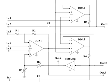 Figure 1: Suggested ARC-Filter’s Circuit
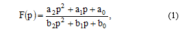 where ai, bj are equation (1) numerator’s and denominator’s coefficients, which depend on components’ parameters and inputs and outputs in circuit on Fig. 2.
A set of transfer function’s numerator coefficients ai defines a type of ARC-filter (LPF, HPF, BPF, RF).
There are transfer functions’ (1) numerator coefficients ai, which are realized in particular ARCF of the Fig. 1 connection circuits, given in Table 1.
The sensitivity functions of the basic parameters of ARCF (Fig. 1) easily correspond to formulas (1) and Table 1.
In the proposed ARCF schemes, typical schemes are applicable, including digital potentiometers or digital switching passive elements, which are described in detail in [35, 36].
The implemented filters’ (LPF, HPF, BPF, RF) transfer functions’ (1) denominator coefficients bj relate to elements of the circuit on Fig. 1 by the following equations:
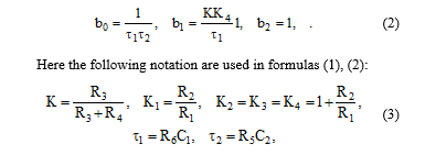 where Rij are resistance of ij-resistor, C1, C2 are capacitance of capacitors С1 and С2.
The active RC-filters, shown in Table 1 and defined as LPF(+), HPF(+), BPF(+), RF(+), have the pole Q-factor, transfer ratio’s and pole frequency’s independent adjustment properties. Here the pole Q-factor adjustment does not change the filter’s transfer ratio and its pole frequency. These filters have the greatest practical interest.
The active RC-filters, defined in Table 1 as LPF, HPF, BPF, RF, do not have the Q-factor, transfer ratio’s and pole frequency’s independent adjustment properties. Here the transfer ratio and pole frequency coefficients may change, when the pole Q-factor is changed.
The active RC-filters, defined in Table 1 as LPF(-), HPF(-), BPF(-), RF(-), have an amplitude-frequency response slope, which corresponds the first-order transfer function. It limits application scope for these circuit solutions.
There are variants of ARCF Fig. 1 inputs and outputs application on Fig. 2-Fig. 6, they provide AFR different modifications’ implementation. In this case, connecting a signal source, for example, to the first input (In.1) assumes that unused inputs are connected to a common bus.
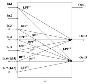 Figure 2: ARCF (Fig. 1) Inputs and Outputs Application Variants, which Provide BPF(+), RF(+), LPF(+),HPF(+) Implementation with Pole Q-Factor Independent Adjustment
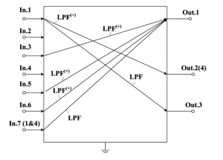 Figure 3: ARCF (Fig. 1) Inputs and Outputs Application, which Provide Low-Pass Filters LPF(+) and LPF Implementation
Table 1: ARC-Filters’ Transfer Functions’ (1) Numerator Coefficients ai, Implemented on Base of Circuit, Given on Fig. 1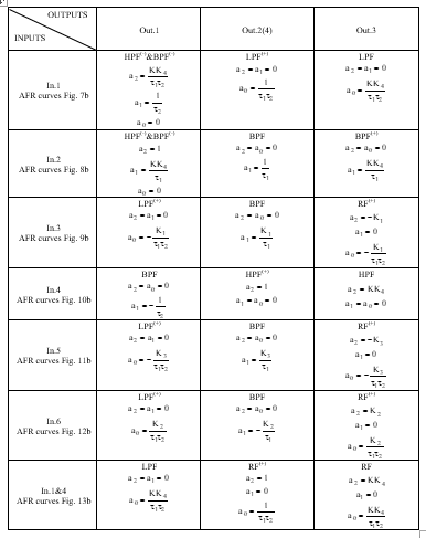
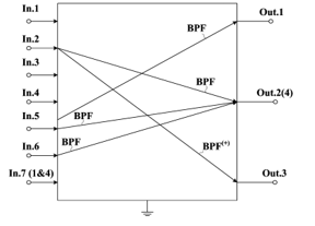 Figure 4: ARCF (Fig. 1) Inputs and Outputs Application, which Provide Band-Pass Filters BPF(+) and BPF Implementation
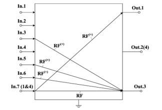 Figure 5: ARCF (Fig. 1) Inputs and Outputs Application, which Provide Rejection Filters RF(+) and RF Implementation
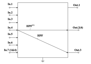 Figure 6: ARCF (Fig. 1) Inputs and Outputs Application, which Provide High-Pass Filters HPF(+) and HPF Implementation
The computer simulation of the ARCF Fig. 1 different modifications, which correspond Fig. 2-Fig. 6, was made in MicroCap on AD830 DDA. It has confirmed the above properties of the suggested ARCF’s circuit solution.
3. Low-Pass Filter LPF(+)
ARCF’s inputs (Fig. 1) are connected according to the circuit, given on Fig. 7a, it provides amplitude-frequency responses of HPF(-)&BPF(-), LPF(+), LPF on outputs Out.1, Out.2(4), Out.3.
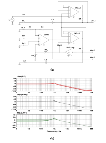 Figure 7: Special ARC-Filter’s Switching Circuit (a) and its AFRs (b)
Analysis of the AFR’s curves (Fig. 7b) has shown, that transfer ratio and pole frequency are not changed in LPF(+), implemented for output Out.2(4), when the pole Q-factor is adjusted (by changing R3 and R4 resistors resistance). At the same time, the pole frequency in this circuit can be tuned using resistors R5 and R6.
4. Band-Pass Filter BPF(+)
ARCF’s inputs (Fig. 1) are connected according to the circuit, given on Fig. 8a, it provides amplitude-frequency responses of HPF(-)&BPF(-), BPF, BPF(+) on outputs Out.1, Out.2(4), Out.3.
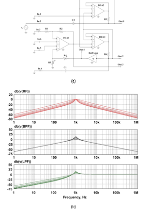 Figure 8: Special ARC-Filter’s Switching Circuit (a) and its Amplitude-Frequency Responses (b)
Based on the BPF(+)‘s AFRs curves (Fig. 8b) for output Out.3, can be concluded, that transfer ratio and pole frequency are not changed, when the pole Q-factor is adjusted (by changing R3 and R4 resistors’ resistance). In this case, the pole frequency in this circuit can be tuned with resistors R5 and R6, and the transfer ratio change with resistors R1 and R2.
5. Rejection Filter RF(+) and Low-Pass Filter LPF (+)
ARCF’s inputs (Fig. 1) are connected according to the circuit, given on Fig. 9a, it provides amplitude-frequency responses of LPF(+), BPF, RF(+) on outputs Out.1, Out.2(4) and Out.3.
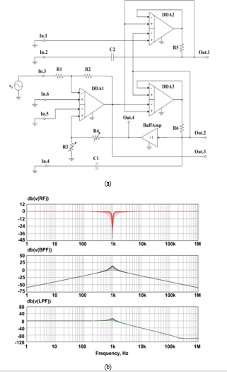 Figure 9: Special ARC-Filter’s Switching Circuit (a) and its Amplitude-Frequency Responses (b)
So the ARC’s curves (Fig. 9b) show, that transfer ratio and pole frequency are not changed in the implemented LPF(+) and RF(+) for outputs Out.1 and Out.3, when the pole Q-factor is adjusted by changing R3 and R4 resistors’ resistance. The pole frequency in this circuit can be tuned with resistors R5 and R6, and the transfer ratio with resistors R1 and R2.
6. High-Pass Filter HPF(+)
ARCF’s inputs (Fig. 1) are connected according to the circuit, given on Fig. 9a, it provides amplitude-frequency responses of BPF, HPF(+) and HPF on outputs Out.1, Out.2(4), Out.3.
It should be noted that when the pole Q-factor is adjusted, the transfer ratio and pole frequency of HPF(+) for output Out.2(4) are not changed, which follows from AFR on Fig. 10b. At the same time, the pole frequency in this circuit can be tuned using resistors R5 and R6.
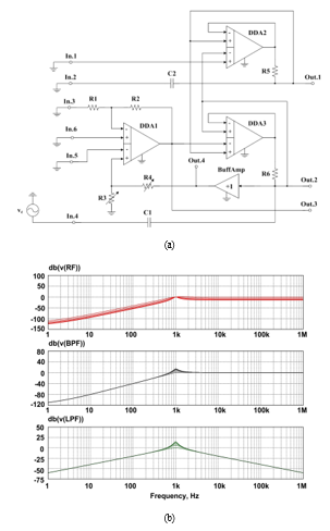 Figure 10: Special ARC-Filter’s Switching Circuit (a) and Amplitude-Frequency Responses (b)
7. Low Pass Filter LPF(+) and Rejection Filter RF(+), Inverting Input Signal
ARCF’s inputs (Fig. 1) are connected according to the circuit, given on Fig. 11a, it provides amplitude-frequency responses of LPF(+), BPF, RF(+). on outputs Out.1, Out.2(4), Out.3.
The given AFRs’ curves’ (Fig. 11b) analysis has shown, that the transfer ratio and pole frequency in LBF(+) and RF(+) for outputs Out.1 and Out.3 are not changed, when the pole Q-factor is adjusted by changing R3 and R4 resistors’ resistance. At the same time, the pole frequency in this circuit can be tuned with resistors R5 and R6, and the transfer ratio with resistors R1 and R2.
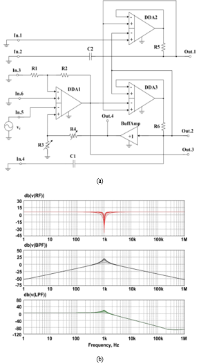 Figure 11: Special ARC-Filter’s Switching Circuit (a) and its Amplitude-Frequency Responses (b)
8. Low Pass Filter LPF (+) and Rejection Filters (+), Non-inverting Input Signal
ARCF’s inputs (Fig. 1) are connected according to the circuit, given on Fig. 12a, it provides amplitude-frequency responses of LPF(+), BPF, RF(+) on outputs Out.1, Out.2(4) and Out.3.
When the pole Q-factor is adjusted (by changing R3 and R4 resistors resistance), the transfer ratio and pole frequency of LPF(+) and RF(+) (for outputs Out.1 and Out.3 correspondently) are not changed. At the same time, the pole frequency in this circuit can be adjusted using resistors R5 and R6, and the transfer ratio using resistors R1 and R2.
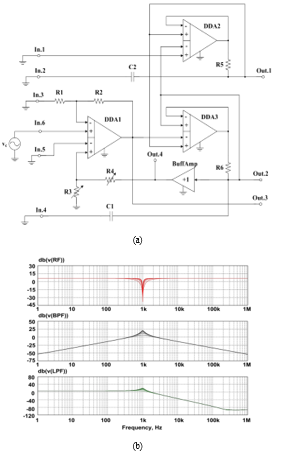 Figure 12: Special ARC-Filter’s Switching Circuit (a) and its AFRs (b)
9. Rejection Filter RF(+)
ARCF’s inputs (Fig. 1) are connected according to Fig. 13a, it provides amplitude-frequency responses of LPF, RF(+), RF on outputs Out.1, Out.2(4), Out.3.
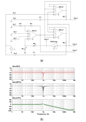 Figure 13: Special ARC-Filter’s Switching Circuit (a) and its Amplitude-Frequency Responses (b)
From the analysis of the AFRs’ curves (Fig. 13b), it may be concluded, that the transfer ratio and pole frequency are not changed in the RF(+), implemented for output Out.2(4), when the pole Q-factor is adjusted (by changing R3 and R4 resistors resistance). At the same time, the pole frequency in this circuit can be tuned using resistors R5 and R6.
10. Conclusion
We have developed a structure of all-pass ARCF with pole Q-factor, transfer ratio and pole frequency independent adjustment for the whole spectrum of amplitude-frequency responses of the second-order filter (LPF, HPF, BPF, RF) implemented. This is a significant advantage of the considered circuit design solutions in comparison with the known ARCF of this class. We recommend using the suggested ARCF as a specialized chip of a structural array because of its universality. It is possible to implement a wide range of frequency selection devices in the said ARCF, because the signal source is connected to one of seven inputs and four outputs.
Conflict of Interest
The authors declare that there is no conflict of interests regarding publication of this paper.
Acknowledgments
The research is carried out at the expense of the Russian Science Foundation Grant (Project No. 18-79-10109).
- W. Chiu and J. Horng, “High-Input and Low-Output Impedance Voltage-Mode Universal Biquadratic Filter Using DDCCs,” in IEEE Transactions on Circuits and Systems II: Express Briefs, vol. 54, no. 8, pp. 649-652, Aug. 2007. DOI: 10.1109/TCSII.2007.899460
- Miao Huijing, Liu Xiaoyan, Tan Boxue, Shen Jin and Wang Yajing, “A universal active filter design method,” 2010 International Conference on Information, Networking and Automation (ICINA), Kunming, 2010, pp. V1-18-V1-22. DOI: 10.1109/ICINA.2010.5636442
- C. Chang, “Universal active current filter with single input and three outputs using CCIIs,” in Electronics Letters, vol. 29, no. 22, pp. 1932-1933, 28 Oct. 1993. DOI: 10.1049/el:19931286
- Xifeng Zhou, Shanshan Li and Jiake Wang, “An electronically tunable active-C current-mode universal filter employing CCCII and OTA,” 2011 IEEE International Conference on Computer Science and Automation Engineering, Shanghai, 2011, pp. 647-651. DOI: 10.1109/CSAE.2011.5952930
- F. Khateb, S. B. A. Dabbous, M. Kumngern and T. Kulej, “Novel current controlled differential-input buffered output active element and its application in all-pass filter,” 2015 38th International Conference on Telecommunications and Signal Processing (TSP), Prague, 2015, pp. 335-338. DOI: 10.1109/TSP.2015.7296279
- P. Ahmadi, B. Maundy, A. S. Elwakil, L. Belostotski and A. Madanayake, “A New Second-Order All-Pass Filter in 130-nm CMOS,” in IEEE Transactions on Circuits and Systems II: Express Briefs, vol. 63, no. 3, pp. 249-253, March 2016. DOI: 10.1109/TCSII.2015.2482578
- B. Metin, N. Herencsar, J. Koton and E. Arslan, “All-pass filter application using electronically tunable DDCC,” 2014 24th International Conference Radioelektronika, Bratislava, 2014, pp. 1-4. DOI: 10.1109/Radioelek.2014.6828413
- L. Mohammadi and K. Koh, “Integrated C-band (4–8 GHz) frequency-tunable & bandwidth-tunable active band-stop filter in 0.13-µm SiGe BiCMOS,” 2015 IEEE MTT-S International Microwave Symposium, Phoenix, AZ, 2015, pp. 1-4. DOI: 10.1109/MWSYM.2015.7167026
- T. S. Arora, M. Gupta and S. Gupta, “Current mode universal filter employing operational transconductance amplifier and third generation current conveyor,” 2016 IEEE 1st International Conference on Power Electronics, Intelligent Control and Energy Systems (ICPEICES), Delhi, 2016, pp. 1-4. DOI: 10.1109/ICPEICES.2016.7853305
- S. Gautam, P. Yunqing, M. Kashif, Y. R. Kafle, Z. Z. Hua and L. Bo, “Study on software phase locked loop for single phase active power filter,” Fifth International Conference on Advances in Recent Technologies in Communication and Computing (ARTCom 2013), Bangalore, 2013, pp. 319-327. doi: 10.1049/cp.2013.2191
- N. Herencsar, J. Jerabek, J. Koton, K. Vrba, S. Minaei and İ. C. Göknar, “Pole frequency and pass-band gain tunable novel fully-differential current-mode all-pass filter,” 2015 IEEE International Symposium on Circuits and Systems (ISCAS), Lisbon, 2015, pp. 2668-2671. DOI: 10.1109/ISCAS.2015.7169235
- N. Herencsar, J. Koton, K. Vrba and O. Cicekoglu, “Low-voltage fully cascadable resistorless transadmittance-mode all-pass filter,” 2014 IEEE 57th International Midwest Symposium on Circuits and Systems (MWSCAS), College Station, TX, 2014, pp. 185-188. DOI: 10.1109/MWSCAS.2014.6908383
- A. Upadhyay and K. Pal, “A DVCC based voltage mode all pass filter using operational amplifier pole,” 2014 International Conference on Power, Control and Embedded Systems (ICPCES), Allahabad, 2014, pp. 1-4. DOI: 10.1109/ICPCES.2014.7062817
- N. Wattikornsirikul and M. Kumngern, “Three-input one-output voltage-mode universal filter using simple OTAs,” 2014 Twelfth International Conference on ICT and Knowledge Engineering, Bangkok, 2014, pp. 28-31. DOI: 10.1109/ICTKE.2014.7001530
- R. Sotner, J. Jerabek, J. Petrzela, K. Vrba and T. Dostal, “Design of fully adjustable solution of band-reject/all-pass filter transfer function using signal flow graph approach,” 2014 24th International Conference Radioelektronika, Bratislava, 2014, pp. 1-4. DOI: 10.1109/Radioelek.2014.6828418
- I. Mondal and N. Krishnapura, “A 2-GHz Bandwidth, 0.25–1.7 ns True-Time-Delay Element Using a Variable-Order All-Pass Filter Architecture in 0.13 $mu$ m CMOS,” in IEEE Journal of Solid-State Circuits, vol. 52, no. 8, pp. 2180-2193, Aug. 2017. doi: 10.1109/JSSC.2017.2693229.
- J. Teifel, R. S. Flores, S. Pearson, C. Begay, K. K. Ma and J. Palmer, “ViArray standard platforms: Rad-hard structured ASICs for digital and mixed-signal applications,” 2012 IEEE Aerospace Conference, Big Sky, MT, 2012, pp. 1-9. DOI: 10.1109/AERO.2012.6187235.
- “Analogue arrays from Sweden, ” SLA description, Dec. 1999, pp. 1-4.
- V. Stornelli, L. Pantoli, G. Leuzzi, G. Ferri, “Fully differential DDA-based fifth and seventh order Bessel low pass filters and buffers for DCR radio systems, ” Analog Integr Circ Sig Process 2013;75(2):305–10. https://doi.org/10.1007/s10470-013-0051-9.
- F. Khateb, T. Kulej, M. Kumngern and C. Psychalinos, “A compact power-efficient 0.5V fully differential difference amplifier, ” AEU – International Journal of Electronics and Communications, 105, 71–77. DOI:10.1016/j.aeue.2019.04.007
- F. Khateb, M. Kumngern, T. Kulej and V. Kledrowetz, “Low-voltage fully differential difference transconductance amplifier,” in IET Circuits, Devices & Systems, vol. 12, no. 1, pp. 73-81, 1 2018. DOI: 10.1049/iet-cds.2017.0057
- H. Alzaher and M. Ismail, “A CMOS fully balanced differential difference amplifier and its applications,” in IEEE Transactions on Circuits and Systems II: Analog and Digital Signal Processing, vol. 48, no. 6, pp. 614-620, June 2001. DOI: 10.1109/82.943332.
- M. Kumngern, F. Khateb, “0.8-V Floating-Gate Differential Difference Current Feedback Operational Amplifier, “2014 11th International Conference on Electrical Engineering/Electronics, Computer, Telecommunications and Information Technology (ECTI-CON), 14-17 May 2014, pp. 1-5. DOI: 10.1109/ECTICon.2014.6839780
- M. Kumngern, K. Klangthan, “0.5-V Fourth-Order Low-Pass Filter, ” 2017 2nd International Conference on Automation, Cognitive Science, Optics, Micro Electro-Mechanical System, and Information Technology (ICACOMIT), Oct. 23, 2017, Jakarta, Indonesia, pp. 119-122. DOI: 10.1109/ICACOMIT.2017.8253398
- J. Wang, Zh. Zhu, S. Liu, R. Ding, “A low-noise programmable gain amplifier with fully balanced differential difference amplifier and class-AB output stage, ” J. Microelectronics, 2017, no. 64, pp. 86–91.
- S.G. Krutchinsky, N.N. Prokopenko, E.A. Zhebrun, N.V. Butyrlagin. The Peculiarities of the Structural Optimization of the Energy-Efficient Precision ARC-Filters on the Base of Classical and Differential Difference Operational Amplifiers // IEEE East-West Design & Test Symposium (EWDTS’2015), 26 – 29 Sep. 2015. – Batumi, Georgia. DOI: 10.1109/EWDTS.2015.7493136
- N. N. Prokopenko, N. V. Butyrlagin, S. G. Krutchinsky, E. A. Zhebrun and A. E. Titov, “The Advanced Circuitry of the Precision Super Capacitances Based on the Classical and Differential Difference Operational Amplifiers,” 2015 IEEE 18th International Symposium on Design and Diagnostics of Electronic Circuits & Systems, Belgrade, 2015, pp. 111-114. DOI: 10.1109/DDECS.2015.46
- D. Jana and A. K. Mal, “Design of low noise amplifier for sensor applications,” 2017 Devices for Integrated Circuit (DevIC), Kalyani, 2017, pp. 451-455.doi: 10.1109/DEVIC.2017.8073990
- Q. Hu, L. Yang and F. Huang, “A 100–170MHz fully-differential Sallen-Key 6th-order low-pass filter for wideband wireless communication,” 2016 International Conference on Integrated Circuits and Microsystems (ICICM), Chengdu, 2016, pp. 324-328. DOI: 10.1109/ICAM.2016.7813617
- J. S. Mincey, C. Briseno-Vidrios, J. Silva-Martinez and C. T. Rodenbeck, “Low-Power Gm-C Filter Employing Current-Reuse Differential Difference Amplifiers,” in IEEE Transactions on Circuits and Systems II: Express Briefs, vol. 64, no. 6, pp. 635-639, June 2017. DOI: 10.1109/TCSII.2016.2599027
- N. Van Helleputte, R. F. Yazicioglu, “Instrumentation amplifier and signal amplification method, ” U.S. Patent 9 294 048, Mar. 22, 2016.
- J. Koton, N. Herencsar, J. W. Horng, “Differential second-order voltage-mode all-pass filter using current conveyors, ” Elektronika ir Elektrotechnika, 2016, vol. 22, no. 5, pp. 52-57. DOI: 10.5755/j01.eie.22.5.16344
- A. Yesil, F. Kacar, “Band-pass filter with high quality factor based on current differencing transconductance amplifier and current amplifier, ” AEU-International Journal of Electronics and Communications, 2017, vol. 75, pp. 63-69. DOI: 10.1016/j.aeue.2017.03.007
- D. Yu. Denisenko, N. N. Prokopenko, “All-pass Active RC Filter Based on Differential Difference Amplifiers, ” Patent Appl. RU 2019107341, March 15, 2019. (In Russian).
- D. Y. Denisenko, Y. I. Ivanov, N. N. Prokopenko and N. A. Dmitrienko, “Digital potentiometers in the tasks of settings precision analog RC-filters taking into account the tolerances for passive components,” 2017 18th International Conference of Young Specialists on Micro/Nanotechnologies and Electron Devices (EDM), Erlagol, 2017, pp. 205-210. https://doi: 10.1109/EDM.2017.7981741
- Digital Potentiometers (DigiPOT). URL: https://www.analog.com/en/products/digital-to-analog-converters/digital-potentiometers.html