
Performance Analysis of Thyristors Switched Capacitors used for Reactive Power Compensation of Induction Motor
Volume 4, Issue 4, Page No 58-64, 2019
Author’s Name: Dmitry Ivanovich Panfilov1,a), Ahmed Elsayed ELGebaly2, Michael Georgievich Astashev3, Alexander Nikolaevich Rozhkov1
View Affiliations
1Department of industrial electronics, Moscow power engineering institute, Moscow, 111250, Russia
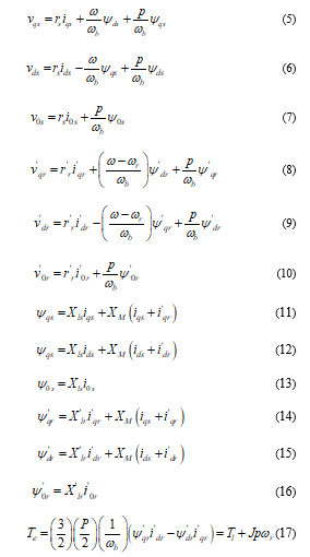
2Electrical power and machines department Faculty of engineering, Tanta university, Tanta, 31527, Egypt
3A G. M. Krzhizhanovsky power engineering institute (JSC ENIN), Moscow, 119991, Russia
a)Author to whom correspondence should be addressed. E-mail: Dmitry.panfilov@inbox.ru
Adv. Sci. Technol. Eng. Syst. J. 4(4), 58-64 (2019); ![]() DOI: 10.25046/aj040408
DOI: 10.25046/aj040408
Keywords: Reactive power compensation, Thyristors switched capacitors, Induction motor starting

Export Citations
This paper analyzes the process of reactive power compensation using thyristors switched capacitors TSC topology based on multiterminal switch during the starting of induction motor. The paper explains the control principle of this TSC topology which depends on the multiterminal switch. To actively track the required reactive power for the dynamic load and to perfectly transit from it from one level to other, proper control system is established. MATLAB/SIMULINK is used to develop a simulation model to prove the dynamic performance of the proposed TSC during the compensation of reactive power required for induction motor during starting.
Received: 29 April 2019, Accepted: 26 June 2019, Published Online: 11 July 2019
1. Introduction
This paper is an extension of work originally presented in 2018 X International Conference on Electrical Power Drive Systems (ICEPDS) under title (Performance Assessment of Thyristors Switched Capacitors during Reactive Power Compensation of Dynamic Load) [1]. It is well known that; the induction motors are the most broadly utilized motors in the world due to their high rigidness [2]. The powers of the used induction motors vary from the fraction of kilowatt up to several megawatt [3]. The induction motors require reactive power during their operation either they are supplied from conventional AC source or through drive system [4]. But, the connection of reactive power compensators with the induction motors improves the power system quality where they are supplied [5]. The compensation of the reactive power may be achieved by the connection of fixed capacitor on the terminals of the induction motor. But, this method doesn’t adapt the requirements of the motor for the various operation modes. The application of dynamically changed reactive power supply improves the power factor for wider operation range particularly during the starting of the motors [6]. The induction motors speed may be changed using dynamically changed reactive power source [7].
Several references [8,9] study the usage of conventional static VAR compensators needed by the induction. The production of harmonics is an essential demerit of the conventional SVCs. Therefore, they require the application of filters [10,11]. The switched-based SVC present a vital solution to remove the harmonics during the control of the reactive power. But, it should be considered that, the switched SVCs have discrete performance during the control of reactive power; consequently, they require different control and design methodology to obtain the smoothest characteristic [12].
This research analyzes the process of reactive power compensation for the starting of induction motor depending on switched SVC. The thyristor switched capacitors TSC which has 25 discrete steps of operation is the type of SVC applied in this study. The design of such TSC topology requires special design to dynamically change the developed capacitive reactive power. The control methodology applied for the TSC topology is established to regulate the proper amount of reactive power during the starting of the induction motor. The detailed induction motor model is illustrated to study the effect of the SVC on its operation. By using MATLAB/SIMULINK package, Simulation model of the whole system is established to demonstrate the TSC performance during the compensation of reactive power.
|
Table 1: The equivalent capacitance obtained by the proposed TSC with four capacitors and seven switches
|
|||||||||||||||||||||||||||||||||||||||||||||||||||||||||||||||||||||||||||||||||||||||||||||||||||||||||||||||||||||||||||||||||||||||||||||||||||||||||||||||||||||||||||||||||||||||||||||||||||||||||||||||||||||||||||||||||||||||||||||||||
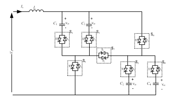 Figure 1: TSC produces 25 discrete levels of capacitive reactive power
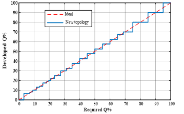 Figure 2: The characteristic of the proposed TSC
2. Principle of operation of multiterminal switch TSC
Figure 1 illustrates the proposed TSC scheme which can produce 25 level of operation by providing 25 different equivalent capacitances [13]. In compared with binary TSC and for the same number of capacitors, the developed scheme produces more steps of operation where the binary TSC only produces 16 steps [14]. Therefore, the developed TSC provides more flexible operation to produce capacitive reactive power while there is no need for application of thyristor-controlled reactor TCR for reactive power regulation. The proposed TSC topology produces zero harmonics during its operation.
Table 1 demonstrates the several equivalent capacitances produced by the proposed TSC. The connected reactor L in the topology is important related to the reduction of current rate of change [15] and related to the restoring of the stored energy on capacitors back to the source [13].
The proposed TSC parameters is obtained depending on an optimization technique which assures the most smooth variation of the distinct characteristic [16,17]. The developed capacitive reactive power has discrete characteristic as shown in Figure 2. The function of control system of this topology is the determination the required reactive power in another words the required susceptance. Therefore, the control system should regulate the operation state of each switch of the seven switches to produce specific capacitance as in Table 1. The TSC reactive power control system needed by induction motor at starting will be explained in section 4.
As shown in Table 1, some of the equivalent capacitance include series connection of certain capacitors. The series connection of capacitors during generation of certain levels of reactive power leads in appearance of permanent different DC voltages on capacitors after termination of the reactive power level generation. To change the equivalent capacitance to another level, the capacitors which were connected in series on previous stage should be discharged. The discharging process should be completed in very short time to make the system response faster. The discharging of capacitors achieved by regenerative method by recovery the capacitors stored energy to the power supply. The recovery process can be accomplished by connection of reactor L shown in the scheme Figure 1.
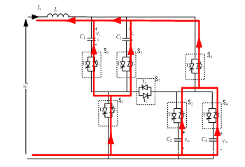 Figure 3: Discharging path for positively charged capacitors of TSC
To discharge all capacitors, the time presents a critical factor, So, in this study, the TSC system is designed to discharge the capacitors in very short less than quarter of the voltage period. The added reactor and any combination of capacitors is considered resonance circuit. By the help of this resonance circuit, the stored energy on capacitors can be recovered to the power source. Figure 3 illustrates the discharging path for the charged capacitors. The regeneration can be completed within time less than the one quarter of the entire period [14]. The semiconductor switches in this scheme has a vital rating related to the maximum amplitude of current during discharging. The inductance value and firing angle to start the process affect the performance of discharging process. The resonance frequencies ωk relates between the inductance L and the total capacitance Ceq by the following relation:
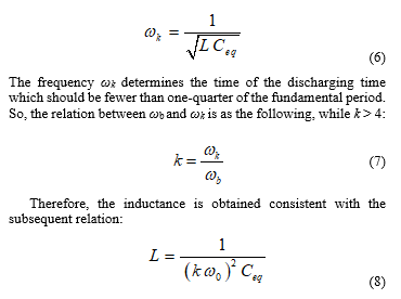 In this study, k is set at 24. The total required capacitance is determined consistent with the reactive power requirement of the induction motor as will be explained in section 5.
3. The Detailed Dynamic Model of the Induction Motor
The three-phase induction motor consists of six windings; three windings are in the stator and three are in the rotor. The equations of the stator voltage are as the following:
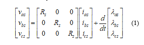 where, vas , vbs and vcs are the voltages on the stator windings, Rs is stator resistance and λas, λbs and λcs are the linkage fluxes of the three windings. The flux linkage can be described as the following
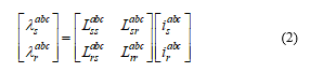 where subscript ‘r’ specifies rotor and ‘s’ specifies stator. Moreover, and are stator and rotor inductance matrixes. As well known, both of and are stator and rotor mutual inductance matrixes which have time variant parameters. To solve the dynamic equation (1), some difficulties should be faced. So, the using of transformation theory through Klark matrix (equation (3)) presents a solution to solve the dynamic model.
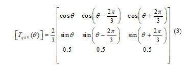 The voltage equations after transformation are presented as in the following equation.
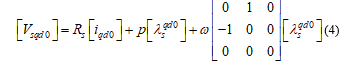 where is the stator windings flux linkage, the arbitrary reference frame currents and ω is the rotational speed reference frame. The arbitrary reference frame equivalent circuits for symmetrical three-phase induction motor are illustrates in Figure 4.
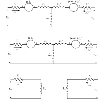 Figure 4: The symmetrical three-phase induction motor arbitrary reference frame equivalent circuits
It is common to present the parameters of machines and power system in ohms, per-unit or percent of base impedance, so, it will be more suitable to express both of flux linkage and voltage equations in terms of reactances instead of inductances as in the following equations [1, 2, 3].
 where ωb is the base electrical angular velocity used to calculate the reactances. The flux linkages in equation 4 are converted to flux linkages per second. ωr is the rotational speed of rotor. Xl is leakage reactance and XM is the mutual reactance. Te and Tl are electromagnetic and load torque respectively. J is the inertia for motor and load. By using the previous dynamic equations, the motor can be analyzed using any simulation package such as MATLAB/SIMULINK used in this paper. All variable states of the induction motor can be determined by this model specially the variables estimate the required reactive power.
4. Control System of Reactive Power for the Operation of Induction Motor
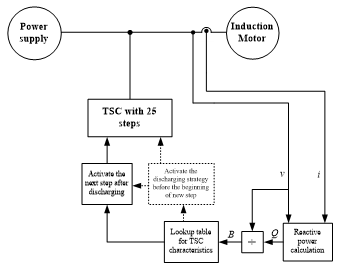 Figure 5: The block diagram for the TSC control system for reactive power compensation
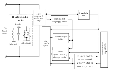 Figure 6: Block diagram of new topology of TSC control system
Figure 5 shows the block diagram of the control system for the proposed TSC to regulate the reactive power of the motor. The voltages and currents of the motor terminal are measured to get the feedback signals. Therefore, the amount of capacitive reactive power is determined. The corresponding amount of susceptance B can be estimated from both of terminal voltage and reactive power. Consequently, the required susceptance presents the input of TSC lookup table characteristic in Table 1 and Figure 2. One step of the 25 steps is the lookup table output. The changing of the developed steps from look up table activates the capacitors discharging process once before the implementation of the following step [13]. Figure 6 illustrates the proposed TSC control system for both implementation of any susceptance and the activation of the discharging process [14].
When the discharging process is activated, the produced capacitive reactive power equals zero. If the next step is activated after the discharging process, the SVC continues the production of reactive power. The control proposed algorithm depends on the tracking of the required reactive power for the motor to produce it by the TSC. The transfer function describes the performance of the TSC can be described as:
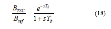 where BTSC is the produced susceptance, Bref is the reference susceptance, Td is the dead-time and Tb is the delay-time [18].
5. Simulation Results of the compensated motor by TSC
In this study, the reactive power compensated induction motor by the proposed TSC is simulated depending on MATLAB/SIMULINK package. The reactive power compensation is imitated throughout the induction motor starting to illustrate the performance of effective control system proposed to regulate the reactive power. Figure illustrates the parallel connection of the TSC in parallel with the motor. The line-to-line voltage of power supply equals 400 V. The induction motor has the following ratings: nominal power of 37.3 kVA, 400 V line-to-line voltage, 50 Hz, 4-poles. The motor has the following parameters: rs = 0.087 Ω, Xls = 0.302 Ω, rr’ = 0.228 Ω, Xlr’ = 0.302 Ω, Xm = 13.08 Ω and inertia constant J = 8 kg.m2.
The ratings of the connected TSC are as the following: rated line voltage of 400 V and rated power of 243 kVAR capacitive. Although the power rating of the TSC is much higher than the rating of the motor itself, the TSC reactive power is enough to compensate the reactive power required by the motor during starting. At free running, the TSC can compensate the reactive power of several connected motors because the required reactive power by the motor is reduced by the speed increment.
If the induction motor starts running, the TSC starts to compensate the reactive power compensation with the full rating then the compensated reactive power is gradually decreased. The TSC control system adjusts the reactive power by producing the maximum reactive power presented by level number 25 (Figure 2 and Table 1) at zero speed. At no-load, the required reactive power by the motor is reduced to lower level presented by level number 2. The motor with and without TSC is simulated to illustrate the TSC influence on the motor performance. The motor needs around 12 seconds to reach its full speed; consequently, the emulation period is 15 seconds which are sufficient to study the influence of the reactive power compensation on the motor performance. Figure 7 shows the supply reactive power in two cases; compensated and uncompensated motor. The using of TSC enables to reduce the total apparent power produced by the power source. Figure 8 shows the produced capacitive reactive power if the motor is compensated. Figure 9 illustrates the step of operation required to produce the corresponding reactive power. Several benefits are achieved by the reactive power compensation. The first advantage is shown in Figure 10; the compensation causes the reduction of the line current of the power source. The second benefit is the enhancement of the motor terminal voltage as illustrated in Figure 11. Therefore, the enhancement of voltage causes the increasing of motor acceleration as illustrated in Figure 12. Due to the reduction of the supply current, the internal losses of the motor are reduced where the internal winging resistance equals r = 0.5 Ω as in Figure 13. The changing of the compensation level leads to the appearance of spikes in the system response. The transition needs one full period to discharge the installed capacitors as explained in section 2.
The power factor of the system is improved due to compensation. This is due to the reduction of the phase shift between the voltage and current as illustrated in Figure 14
As explained earlier, the transition between two steps of reactive power requires the discharging process to be activated. To discuss this interval, the instantaneous waveforms of currents and voltages are illustrated. Throughout the changing of the developed steps from 25 to 24, Figure 15(a) shows the waveform of supply voltage and its produced current. As shown in the figure, the phase shift between current and voltage is around zero. In steady state, the waveform of the supply current is pure sin wave except some distortion during the transition period. The time span of the distorted current equals about one period. As shown in Figure 15(b), the phase shift between the TSC current and the supply terminal voltage is 90° lead. During the transient period, the TSC supplies zero current except spike current owing to the process of capacitors discharging. Furthermore, Figure15(c) illustrates that the voltage and the motor current are not in phase; therefore, the power factor below unity. Nevertheless, the usage of TSC enhances the power factor to unity by reducing the phase-shift between the voltage and current.
6. Conclusion
TSC has been developed as a reactive power supply to produce the required reactive power for the induction motor during starting period. The circuit topology of the proposed TSC is introduced to control the reactive power with 25 discrete steps. The principle of operation and characteristic of the proposed TSC scheme is analyzed to produce compensation system suitable for dynamically changed load. The induction motor and TSC dynamics have been introduced to analyze the dynamic performance of the whole system. The control system block diagram is constructed to track the needed reactive power for the motor. The concept of regeneration of capacitive unit energy has been explained to assure the dynamic reactive power production for the TSC. The design parameters of the TSC have been determined to produce the required reactive power and to carry out the discharging process effectively. using MATLAB/SIMULINK package, simulation and model have been developed for the whole system contains induction motor, the TSC and its control system. The simulation results demonstrate the efficiency of the proposed TSC topology during the reactive power compensation needed by the induction motor through the dynamic performance. The control system efficiently controls the TSC response to actively produce the proper reactive power.
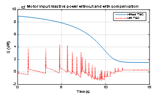 Figure 7: The supply reactive power produced for the motor in the compensated and uncompensated cases
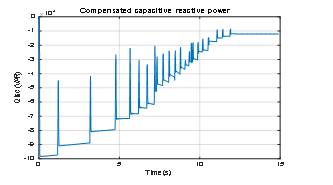 Figure 8: TSC produced capacitive reactive power
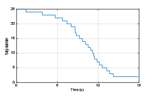 Figure 9: TSC step number to regulate the produced reactive power.
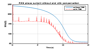 Figure 10: The power supply phase current throughout the motor starting
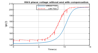 Figure 11: The IM motor terminal phase voltage throughout starting period
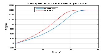 Figure 12: The speed of the IM during starting period
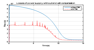 Figure 13: The internal supply losses during starting
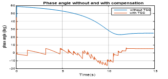 Figure 14. Phase shift between phase voltage and current
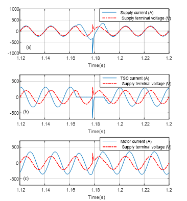 Figure 15. Waveforms of the source terminal phase voltage and current, motor current and TSC current throughout the transition between two levels between 25 and 24 steps
Acknowledgment
The study is achieved at Stock Company G. M. Krzhizhanovsky Power Engineering Institute in the framework of the project ” Development of a controlled source of reactive power with the absence of the higher-order harmonics currents during the regulation of the electrical energy and with the improved technical and economic indicators on the basis of the domestic component base of power electronics for automatic control of the voltage and the power flows in the electric power distribution networks of 6-110 kV (RFMEFI57917X0140)” with the financial support of the Ministry of Education and Science of the Russian Federation.
- D. I. Panfilov, A. E. ElGebaly, M. G. Astashev and Alexander N. Rozhkov. “Performance Assessment of Thyristors Switched Capacitors during Reactive Power Compensation of Dynamic Load.” 2018 10th International Conference on Electrical Power Drive Systems, ICEPDS, Novocherkassk, Russia, 2018. https://doi.org/10.1109/ICEPDS.2018.8571426
- Krause, Paul C., Oleg Wasynczuk, and Scott D. Sudhoff. Analysis of Electric Machinery and Drive Systems. IEEE, 2002.
- Bird, J. in Electrical and Electronic Principles and Technology 467–485 (Routledge, 2018). doi:10.4324/9781315561875-26.
- Nigim, K. in Handbook of Automotive Power Electronics and Motor Drives 387–404 (CRC Press, 2017). doi:10.1201/9781420028157
- El-Saady, Gaber, Ali M. Yousef, and Farag K. Abo-Elyousr. “Fuzzy FACTS Voltage Regulator for Isolated Wind Energy Conversion Systems under Different Wind Speed and Loading Conditions.” 2016 Saudi Arabia Smart Grid Conference, SASG 2016. doi: 10.1109/SASG.2016.7849677
- Omran, A. S., Abbasy, N. H. & Hamdy, R. A. Enhanced performance of substation dynamics during large induction motor starting using SVC. Alexandria Engineering Journal 57, 4059–4070 (2018)
- K. Smitanjali et.al “Design of Digital-Static VAR Compensator for Induction Motor” Imperial Journal of Interdisciplinary Research (IJIR), Vol-3, Issue-5, 2017
- A. Abd Elraouf et.al, “Ant lion-Based Optimization of Facts Devices’ Controllers to Enhance Three Phase Induction Motor Dynamic Performance“ European Journal of Research No 4 (4), 2017
- A. E. ElGebaly, A. El-Wahab Hassan, M. K. El-Nemr, “Reactive Power Compensation by Multilevel Inverter STATCOM for Railways Power Grid.” in Proceedings of the 2019 IEEE Conference of Russian Young Researchers in Electrical and Electronic Engineering, ElConRus, Moscow, Russia, 28-31 January 2019. doi: 10.1109/EIConRus.2019.8657058
- D. I. Panfilov, A. E. ElGebaly, “Modified Thyristor Controlled Reactors for Static VAR Compensators” 2016 IEEE 6th International Conference on Power and Energy (PECON 2016), Melaka, Malaysia, November 2016.
- D. I. Panfilov, A. E. Elgebaly and M. G. Astashev, “Design and Assessment of Static VAR Compensator on Railways Power Grid Operation under Normal and Contingencies Conditions”, 16th EEEIC conference, Florence, Italy, 7-10 June 2016
- D. I. Panfilov, A. E. ElGebaly and M. G. Astashev, “Design and evaluation of control system for static VAR compensators with thyristors switched reactors” IEEE 58th International Scientific Conference on Power and Electrical Engineering of Riga Technical University (RTUCON), Riga, Latvia, 12-13 October 2017
- D. I. Panfilov, A. E. ElGebaly, M. G. Astashev and A. Rozhkov “New Approach for Thyristors Switched Capacitors Design for Static VAR Compensator Systems” 19th International Conference of Young Specialists on Micro/Nanotechnologies and Electron Devices June 29 – July 3, 2018
- Panfilov, D. I., ElGebaly, A., Rozhkov, A. N. & Astashev, M. “Control Strategy of Thyristors Switched SVCs with High Power Quality”. Transactions on Environment and Electrical Engineering 3, 15 (2018)
- Panfilov, D. I., Elgebaly, A. E., Astashev, M. G. & Rozhkov, A. N. “Control System Operation in Thyristors Switched SVCs with Improved Quality of Reactive Power”. in Proceedings – 2018 IEEE International Conference on Environment and Electrical Engineering and 2018 IEEE Industrial and Commercial Power Systems Europe, EEEIC/I and CPS Europe 2018 (Institute of Electrical and Electronics Engineers Inc., 2018). doi:10.1109/EEEIC.2018.8493791
- D. I. Panfilov, A. E. ElGebaly and M. G. Astashev, “Design and Optimization of New Thyristors Controlled Reactors with Zero Harmonic Content”, 18th International Conference of Young Specialists on Micro/Nanotechnologies and Electron Devices June 29 – July 3, 2017
- A. E. Elgebaly, D. I. Panfilov and M. G. Astashev “Comparative Evaluation of Binary and Conventional Static VAR Compensators” Mechanics, Materials Science & Engineering journal (mmse), vol. 17, 2018
- Panfilov, D. I., Elgebaly, A. E. & Astashev, M. G. Implementation of thyristors controlled reactors for reactive power control with zero harmonics content. in 17th IEEE International Conference on Smart Technologies, EUROCON 2017 – Conference Proceedings 353–358. doi:10.1109/EUROCON.2017.8011134