
Frequency-Tunable Narrow-Band Ladder-Shape Microstrip Patch Antenna for TV Applications
Volume 4, Issue 4, Page No 51-57, 2019
Author’s Name: Maria Moussaa), Mervat Madi, Karim Kabalan
View Affiliations
Electrical and Computer Engineering Department, American University of Beirut, 1107 2020, Lebanon
a)Author to whom correspondence should be addressed. E-mail: mnm33@mail.aub.edu
Adv. Sci. Technol. Eng. Syst. J. 4(4), 51-57 (2019); ![]() DOI: 10.25046/aj040407
DOI: 10.25046/aj040407
Keywords: Digital TV, UHF, Ladder shape, Frequency tuning, Varactors

Export Citations
In this paper, a frequency-tunable antenna is proposed based on a previous antenna which has a ladder shape and a size of 120 x 50 mm2. It is fed using a coaxial cable and it is operational at 700 MHz which is in the UHF band with a bandwidth of 30 MHz. Varactors, having a very low resistance value and a wide range of capacitance values, are implemented on the surface of the antenna which achieves tunability in the DTV applications band used for mobile handheld devices. By using such varactors, the electromagnetic characteristics of this antenna could be changed by changing its electrical length. Multiple cases are studied; either adding a varactor on each step of the ladder antenna or adding only one varactor in a certain well justified position. The operating frequency is swept in different ranges where all of the obtained frequencies could be used for digital TV broadcasting on mobile devices.
Received: 11 April 2019, Accepted: 26 June 2019, Published Online: 11 July 2019
1. Introduction
Digital TV broadcasting is now the median of exchanging information and that is thanks to the progress in digital TV technology in the form of wireless devices as well as the ways of sending and receiving signals. The new mobile devices have an attractive feature which is to allow users to watch TV on their own handheld devices; however, this feature presents some challenges in the field of designing antennas for this purpose. The antenna has to have a small size to fit in the devices and a high performance to satisfy interested users.
This paper is an extension of the work originally presented in the conference paper entitled “Ladder Shape Microstrip Patch Antenna”, [1]. It is known that the operational frequency and the size of the antenna are inversely proportional. Since our targeted frequency is in the UHF band, it is then obvious that the size of the antenna operating in the high MHz range will increase. One advantage in the design process is that the designer is capable of slightly sacrificing the efficiency of the antenna because digital TV is a receive-only system in which lower total efficiency is acceptable as stated in [2].
Other than the fact that the antenna has to have a small size, it has to have good impedance matching conditions also. This is where the designer is required to add a matching circuit in the purpose of achieving the best possible power transfer between the amplifier and the antenna, which leads to the optimal antenna efficiency. Also, the designer has to take into account the fact that all the used components in the matching circuit add some losses to the design, which affects the whole performance of the system.
In the literature, there exists many papers that present designs of digital TV broadcasting antennas for mobile handheld devices. Some of these antennas are the grating monopole antenna, [3], having dimensions of 240 x 35 mm2 and operating between 458 MHz and 960 MHz, the asymmetric fork shaped monopole antenna, [4], having dimensions of 245 x 35 mm2 and operating between 451 MHz and 912 MHz, the coplanar waveguide-fed dipole antenna, [5], having dimensions of 241 x 58.5 mm2 and operating between 430 MHz and 1180 MHz and the monopole slot antenna, [6], of dimensions 128 x 51 mm2 and operating at 600 MHz. In [7], two small microstrip antennas and one planar inverted F antenna are proposed. These antennas are used in the TV band for transmission of cognitive radios. The three of them operate between 700 MHz and 900 MHz. Some new references could be found in the literature such as [8] in which the authors designed and fabricated a flexible printed active antenna having a meander line shape for the DTV reception. It has a size of 180 x 50 mm2 and a wide operational band ranging from 510 MHz to 790 MHz due to the usage of coplanar waveguide feeding technique. This antenna has an omnidirectional radiation pattern and a maximum gain of about 18 dB. A compact 46 x 46 mm2 antenna is designed in [9] covering a wide band from 490 MHz to 720 MHz. The bandwidth enhancement is achieved by changing the size of the ground plane of the antenna and the size reduction is achieved by incorporating the meander line shape in the radiating patch.
In [1], the goal was to design a small antenna for digital TV after modifying the antenna proposed in [10], which is also a ladder shaped antenna but operational at 90 GHz. Considerable modifications were done on the latter one to function in the MHz frequencies despite the fact that wireless devices impose some size constraints on the antenna. The resulting patch antenna has the shape of a ladder and a size of 120 x 50 mm2 which overrides some of the antennas presented in the literature. Many of the ladder dimensions were studied in [1] to try to improve the matching conditions. The software used for the design and simulation of the antenna is HFSS. It is then fabricated and tested. The simulated and measured results showed good agreement. It has a narrow operational bandwidth of 30 MHz only ranging from 685 MHz to 715 MHz, which do not cover the whole UHF band channels. The solution proposed for that issue is to add surface mounted varactors to the ladder patch antenna to be able to tune the operational bandwidth. A DC bias voltage should be applied to the varactors to change their capacitance values and hence achieve frequency tunability to different UHF channels.
In the upcoming wireless communication systems, reconfigurable antennas are used widely for many reasons. A re-configurable antenna could have the ability of changing many of its characteristics. Frequency, radiation pattern, bandwidth and polarization could be altered to adapt to the environment, [11], using a reconfigurable antenna. Besides their re-configurable capability, re-configurable antennas contain many other features such as reduced cost, size miniaturization and multipurpose functions and they use microstrip antennas as a platform. In addition, recent systems must be able to receive signals over a wide range of frequencies so they require, as stated in [12], either wide-band or tunable narrow-band antennas. The requirement of receiver filters is relaxed because tunable narrow-band antennas, in contrary to broadband antennas, provide frequency selectivity. Tunable antennas, [13], are of interest for wireless communication systems because they could substitute multiple antennas operating at different frequencies, which will reduce the implementation size and its cost as well as the complexity of the system. Another advantage presented by such antennas is the ability to reject the interference from services coexisting in the spectrum. Slot antennas are one of the common types of antennas used in frequency tuning because varactors or switches could be used easily to change their resonant frequency. The frequency tuning is achieved by varying the effective length of the slots using varactor diodes embedded across the slots. Therefore, a tunable antenna could be obtained by loading the patch antennas with varactor diodes, [14], thus having a change in the resonant frequency of the patch.
The authors of [15] present a slot antenna that uses switches to change its electrical length and obtain an effective wide bandwidth. A small patch antenna that could be tuned to different frequencies, ranging from 800MHz to 900 MHz, is designed in [16], this antenna uses variable capacitors and transistors. A radio baseband processor sends commands to a digital control unit implemented in the antenna to control it. In [17], two lumped variable capacitors, also known as varactors, are placed in properly chosen positions on a slot antenna. The antenna is changed to a dual-band antenna having two operational frequencies that could be controlled individually.
In this paper, the varactors are placed according to three different scenarios. The first thing done is to plot the current magnitude on the surface of the antenna in [1] and indicate the points where it is the highest and the lowest. The first scenario is designed by placing a varactor component where the current gets cancelled out, which is in the middle of each ladder step. The two other scenarios are designed by choosing two different points where the current is circulating with high magnitude. These two points appeared to be on the side strip connecting the ladder elements at the same side of the feeding point, one between the third and the fourth element and the other one is between the fourth and the fifth ladder element. Two designs were tested for the second and third scenarios; first, the copper strip facing the varactor had to be removed to avoid short-circuiting the inductors and drive the current to pass through the varactor. The second design was done by removing all strips similar to the one facing the varactor from the ladder patch. All the proposed designs were fabricated and tested and good agreement was obtained between the simulated and the measured reflection coefficients.
2. Original Ladder Antenna: Design and Fabrication
The antenna in [1] is designed with a size of 120 x 50 mm2 on an FR4 epoxy substrate with a dielectric constant of 4.4 and a thickness of 1.6 mm. All the dimensions of the antenna are shown in Figure 1(a).
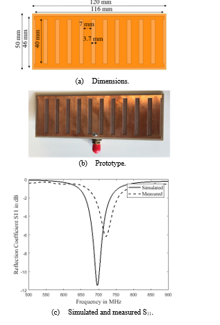 Figure 1: Original ladder shape antenna.
The substrate has a rectangular shape of length 120 mm and a width of 50 mm. The patch has also a rectangular shape of length 116 mm and a width of 46 mm which means that it is smaller than the substrate by 2 mm from each side. The ladder is composed of eleven copper rectangular steps of length 40 mm and of width 7 mm with a spacing of 3.7 mm between each two steps. Finally, the width of each of the two side strips connecting the eleven steps is 3 mm. As already said, the antenna is fed using a coaxial cable and the position of the feeding point was chosen to be in the middle of one of the side strips connecting the ladder elements. A parametric study was done before making the best choice of the feeding position to get the best possible performance of the antenna. The fact that this antenna occupy the entire space of the PCB does not affect the addition of other antennas necessary for the functionality of the device because most of the antennas designed now are very small strip antennas and could use different PCBs.
After the fabrication of the antenna as shown in Figure 1(b), measurements were done on its reflection coefficient. Both the simulated and the measured S11 are shown in Figure 1(c). There is a good agreement between the simulated and the measured results. The value of -6 dB is the threshold of acceptable S11 values for TV antennas therefore the antenna is found to be operational at 700 MHz with a bandwidth of 30 MHz.
The reflection coefficient of the antenna shows that it has a narrow band covering only one TV channel. However, to be able to cover a wider bandwidth in the UHF band, many solutions could be proposed one of which is the use of surface mounted varactors and changing their capacitance values which allows the tuning of the operational frequency of the antenna to different UHF channels.
3. Optimization Approaches
To improve matching conditions at 700 MHz, four approaches were tested in [1]. The first approach, Figure 2(a), was to decrease the number of ladder steps to six. The second, Figure 2(b), was to use the design obtained after applying the first approach and increase the width of the steps to 10 mm which is an increase of 43% of their original width. The third approach, Figure 2(c), was to reuse the original design and subtract eleven slots of size 5 x 2 mm2 from both, upper and lower, side strips connecting the steps making them look like film strips. The final approach tested, Figure 2(d), was to decrease the number of slots subtracted to six and check their influence on the reflection coefficient. The four approaches mentioned are combined with Figure 2(e) that shows the reflection coefficients of the antennas obtained after applying these approaches as well as that of the original antenna simulated using Ansoft HFSS.
No major improvement is shown in the reflection coefficient of the antenna. Instead, resonant frequency is shifted away from 700 MHz in the four cases. Therefore, since the chosen frequency is 700 MHz and also thanks to the simplicity of the design and its easy fabrication, the antenna of the original design is the one chosen to be fabricated and measured. The network analyzer used to do the measurements is the “FieldFox RF Analyzer N9914A” from the Keysight Company. A small acceptable difference between the simulated and the measured S11 could be noticed and it is caused by some fabrication losses therefore, the ladder antenna fabricated is a good candidate to be used for TV applications.
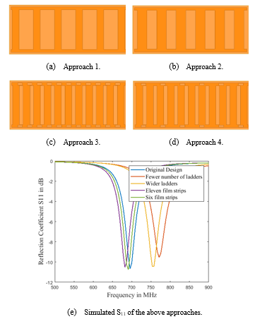 Figure 2: Investigated optimization approaches.
4. Frequency Tunable Ladder Antenna Scenarios: Designs and Fabrication
The addition of varactor diodes along the current path leads to changing the electrical length of the patch and hence the operating frequency. It all depends on the capacitance value of the varactor; for some capacitances the electrical length increase and the resonant frequency decrease and for some other cases, the inverse occurs.
To plainly explain the effect of the capacitance on the transmission line length, it is necessary to introduce the Smith Chart. The Smith Chart is a way of graphically determining transmission line parameters rather than mathematically. Consider a transmission line, it has an impedance which is usually a complex number expressed by (1) where R is the resistance and X is the reactance and can be plotted on the smith chart using the resistance and the reactance circles. A complete circle on the Smith Chart represents a half wavelength transmission line. One of the important applications of a Smith Chart is the length calculation of a short-circuited piece of transmission line to provide a required capacitive or inductive reactance. The addition of a series RC circuit will change the impedance of the transmission line by adding R to its real part and Xc, calculated using (2), to its imaginary part.
 is the frequency in Hertz and C is the capacitance in Farads. Any change in the position of the transmission line impedance point on the Smith Chart, caused by adding matching circuits such as a series RC circuit, will lead to a change in the electrical length of the transmission line as well as its impedance which modifies its matching conditions. The electrical length will either increase or decrease, therefore the operational frequency which is directly related to it, will also change. The distance traveled by a current signal along a transmission line is expressed in relation to its source frequency. The wavelength calculated by (3), where c is the speed of light, is this distance considered for a given frequency.
 In the two suggested scenarios, the varactors are connected serially across a slot subtracted from the radiating patch, which means between two halves of the patch as in [18] and [19]. According to [20], the tunability of the antenna is therefore achieved by cutting small slots from the copper lines and inserting varactors in their place.
The diode model used here is a serial connection between a capacitor and a resistor as shown in Figure 3. The resistor has a very small value of 0.01 Ω. The capacitance of the varactor that is used, 1SV325, is varied between 7 pF and 80 pF when a reverse voltage between 0V and 6V is applied.
 Figure 3: Used configuration of the varactor model depending on resistance R and capacitance C implemented in series.
In what follows, the simulated reflection coefficients are presented for some capacitance values ranging between 7 pF and 80 pF. The measured reflection coefficients are captured while varying the DC bias voltage. It is varied between 0V and 6V for the case of only one varactor added to the surface of the ladder patch antenna represented by scenarios 2 and 3 in the following figures. However, the voltage could be varied in a greater range for the antenna of scenario 1 that has a varactor added to each of its ladder steps because the varactors are in a parallel connection to each other so the voltage would be divided across all the varactors.
Figure 4(a) represents the first antenna scenario where eleven varactors are added each in the middle of one of the steps, with the simulated S11 in Figure 4(b) and the measured S11 in Figure 4(c).
In the second antenna scenario, the varactor is added between the third and the fourth ladder step. Figure 5(a) represents the first design of the second scenario with only one copper strip removed. The simulated S11 is represented in Figure 5(b) and the measured S11 in Figure 5(c).
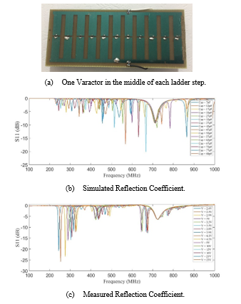 Figure 4: Scenario 1.
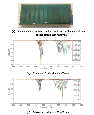 Figure 5: Scenario 2 – Design 1.
Figure 6(a) represents the second design of the second scenario with all copper strips removed. Its simulated S11 is represented in Figure 6(b) and the measured S11 in Figure 6(c).
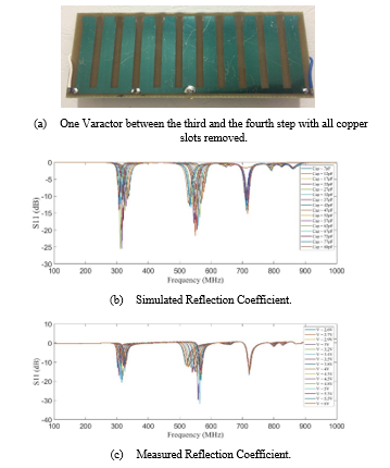 Figure 6: Scenario 2 – Design 2.
 Figure 7: Scenario 3 – Design 1.
In the third antenna scenario, the varactor is added between the fourth and the fifth ladder step. Figure 7(a) represents the first design of the last scenario where only one copper strip is removed. The simulated S11 is represented in Figure 7(b) and the measured S11 in Figure 7(c).
Figure 8(a) represents the second design of the last scenario with all copper strips removed. Its simulated S11 is represented in Figure 8(b) and the measured S11 in Figure 8(c).
In the figures showing the simulated and the measured reflection coefficients for all the antennas deigned, a slight difference could be noticed. This difference is due to the fabrications inaccuracies as well as the losses that could be encountered in the measurement process. However, it is well shown that all the tunable frequencies fall in the same frequency ranges when comparing simulated and measured results for each design.
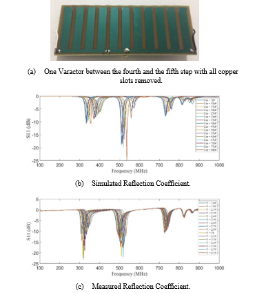 Figure 8: Scenario 3 – Design 2.
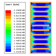 Figure 9: Current distribution for antenna [1].
5. Current Distribution
Figure 9 shows the current distribution on the surface of the ladder patch antenna in [1] at the resonant frequency 700 MHz. It is shown that the current magnitude is not equal in all of the points on the patch; the current on the ladder steps is lower than the one circulating on the side strips connecting them. This is obvious since the current is being canceled out in the middle of the steps because of the fact that it is traveling in opposite directions.
Figure 10 represents the current distribution on the surface of the ladder patch for the five tunable designs discussed above at 700 MHz frequency.
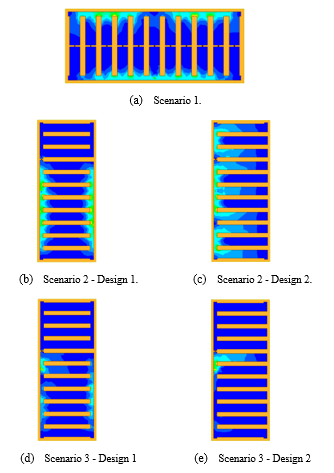 Figure 10: Current distribution for the tunable antennas.
6. Radiation Characteristics
Figure 11(a) shows antenna [1] positioned in the xyz-plane. The three-dimensional radiation pattern of the antenna is shown in Figure 11(b). The main lobe of the antenna is directed in the plane formed by theta equals 90 and phi equals 45 .
Figure 12(a) represents the first antenna design of the second scenario which is having the varactor placed after the third step and removing the copper strip facing it. Two plots of the radiation pattern are presented in Figures 12(b) and 12(c) for resonating frequencies 840 MHz and 870 MHz respectively. Both plots show that the main lobe changed its direction when compared to that of antenna [1].
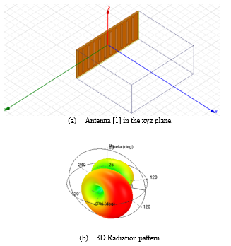 Figure 11: Antenna [1] – Radiation Characteristics.
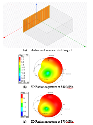 Figure 12: Antenna of scenario 2 – Design 1 – Radiation Characteristics.
It is shown that the gain of this antenna is negative; that is due to its small size compared to what it should have been for operational frequencies in the UHF band. For 700 MHz frequency, the wavelength is around 400 mm however the length of this antenna is 120 mm, which means that the current is circulating on a path that is much smaller than what it should be. However, as already stated in the introduction, this antenna is considered as a receive-only system in which efficiency could be sacrificed more than in a transmit-system.
7. Conclusion
The antennas presented in this paper are an extension of the ladder-shape microstrip patch antenna design presented in the conference paper [1]. When comparing the antenna presented in [1] to other antennas in the literature designed for the same purpose, it shows good improvement in terms of the compactness of its size. It has a length of 120 mm whereas other antennas are of length 240 mm, [3], and 245 mm, [4]. Even though its size suits most of the mobile phones used in the market, this antenna has one drawback which is its narrow operational bandwidth of 30 MHz.
The proposed solution in this paper is to transform this antenna into a frequency tunable antenna by adding varactors onto its surface. A slight change in the geometrical shape of the antenna will create new current paths and new radiation edges which will introduce multiple shifts in the resonant frequency. According to [21], the position of the varactors obviously affect the current flow path, so to tune the obtained resonant frequency, changing these positions is a must.
The varactors are placed in certain positions that achieve frequency tuning while keeping sufficient matching conditions with minimal perturbation. The antennas presented in this paper resonated on new sets of frequencies falling between 200 MHz and 1 GHz, which allows them to be used for Digital TV broadcasting applications on mobile handheld devices.
These antennas have a negative gain because of their small size according to their frequency of operation however, many techniques could be used to improve the antenna gain such as changing the substrate and using a different material having lower losses such as air, adding parasitic patches or meandering edges, cutting parts of the ground plane, etc…
Acknowledgment
The authors would like to acknowledge the support of Mr. Issam Darwish and Mr. Mohammad Darwish for supporting this work.
- M. Moussa, M. Madi and K. Kabalan, “Ladder Shape Microstrip Patch Antenna,” in International Conference on High Peformance Computing and Simulation, Orleans, France, July 2018.
- P. Vainikainen, J. Holopainen and M. Kyro, “Antennas for Digital Television Receivers in Mobile Terminals,” Proceedings of the IEEE, vol. 100, no. 7, pp. 2341-2348, July 2012.
- C.-Y. Huang, B.-M. Jeng and J.-S. Kuo, “Grating Monopole Antenna for DVB-T Applications,” IEEE Transactions on Antennas and Propagation, vol. 56, no. 6, pp. 1775-1776, June 2008.
- C.-Y. Huang, B.-M. Jeng and C.-F. Yang, “Wideband monopole antenna for DVB-T applications,” Electronics Letters, vol. 44, no. 25, pp. 1448-1450, December 2008.
- O. T.-C. Chen and C.-Y. Tsai, “CPW-Fed Wideband Printed Dipole Antenna for Digital TV Applications,” IEEE Transactions on Antennas and Propagation, vol. 59, no. 12, pp. 4826-4830, December 2011.
- C.-Y. Tsai and O. T.-C. Chen, “Compact Broadband Monopole Slot Antenna for Digital TV Applications,” in IEEE Asia-Pacific Conference on Antennas and Propagation, Singapore, October 2012.
- M. Y. Abou Shahine, M. Husseini, A. H. Ramadan, K. Kabalan and Y. Nasser, “Antenna Designs for Cognitive Radio Applications in the TV Band,” International Journal of Scientific & Engineering Research, vol. 6, no. 2, pp. 975-980, February 2015.
- T. Pratumsiri and P. Janpugdee, “Flexible Printed Active Antenna for Digital Television Reception,” in Progress in Electromagnetics Research Symposium (PIERS-Toyama), Toyama, Japan, August 2018.
- S. Bhole, A. Rathod, S. Doddipalli, S. Kannaiyan and A. Kothari, “A Compact Planar Antenna with Meander Lines for TV White Space Applications,” in IEEE International Students Conference on Electrical, Electronics and Computer Science, Bhopal, India, November 2018.
- R. K. Venkata, D. Mrthy and I. a. N. M. N. Govardhani, “Multi-Band Ladder-Shape Micro-Strip Patch Antenna,” International Journal of Scientific & Engineering Research, vol. 3, no. 3, pp. 1-6, March 2012.
- G. Singh and m. Kumar, “Design of Frequency Reconfigurable Microstrip Patch Antenna,” in 6th International Conference on Industrial and Information Systems, Kandy, Sri Lanka, 2011.
- M. S. Nishamol, C. K. Aanandan, P. Mohanan and K. Vasudevan, “Dual Frequency Reconfigurable Microstrip Antenna Using Varactor Diodes,” in XXXth URSI General Assembly and Scientific Symposium, Istanbul, Turkey, August 2011.
- A. Khidre, F. Yang and A. Elsherbeni, “A Patch Antenna with a Varactor-Loaded Slot for Reconfigurable Dual-Band Operation,” IEEE Transactions on Antennas and Propagation, vol. 63, no. 2, pp. 755-760, February 2015.
- B. Babakhani and K. S. Sharma, “Investigations on Frequency Agile Microstrip Patch Antenna Loaded with Varactor Diode,” in IEEE Antennas and Propagation Society International Symposium (APSURSI), Orlando, FL, USA, July 2013.
- D. Peroulis, K. Sarabandi and L. Katehi, “Design of Reconfigurable Slot Antennas,” IEEE Transactions on Antennas and Propagation, vol. 53, no. 2, pp. 645-654, February 2005.
- J. T. Aberle, S.-H. Oh, D. T. Auckland and S. D. Rogers, “Reconfigurable Antennas for Wireless Devices,” IEEE Antennas and Propagation Magazine, vol. 45, no. 6, pp. 148-154, December 2003.
- N. Behdad and K. Sarabandi, “Dual-Band Reconfigurable Antenna with a Very Wide Tunability Range,” IEEE Transactions on Antennas and Propagation, vol. 2006, no. 2, pp. 409-416, February 2006.
- N. Fayyaz, S. Safavi-Naeini, E. Shin and N. Hodjat, “A Novel electronically Tunable Rectangular Patch Antenna with One Octave Bandwidth,” in IEEE Canadian Conference on Electrical and Computer Engineering, Waterloo, Ontario, Canada, May 1998.
- S. V. Hum and H. Y. Xiong, “Analysis and Design of a Differentially-Fed Frequency Agile Microstrip Patch Antenna,” IEEE Transactions on Antennas and Propagation, vol. 58, no. 10, pp. 3122-3130, October 2010.
- J. Costantine, C. Christodoulo and S. E. Barbin, “A New Reconfigurable Multi Band Patch Antenna,” in SBMO/IEEE MTT-S International Microwave and Optoelectronics Conference, Brazil, October 2007.
- M. A. Madi, M. Husseini, A. Ramadan, K. Y. Kabalan and A. El-Hajj, “A Reconfigurable Cedar-Shaped Microstrip Antenna for Wireless Applications,” Progress in Electromagnetics Research, vol. 25, pp. 209-221, 2012.