Nonlinear Analytic Modeling for Novel Linear Variable Reluctance Motors

Adv. Sci. Technol. Eng. Syst. J. 4(2), 190–196 (2019);
 DOI: 10.25046/aj040225
In this paper, an analytical modeling is proposed to compute the static and dynamic characteristics of linear variable reluctance motors with taking account of the saturation and the non-linearity of the magnetic circuit. The proposed model is based on the Fourier series expression of the phase flux in which the variation of the linkage flux with phase current is defined by arc tangent function. Then, an analytical expression for the co-energy and electromagnetic forces are derivative. The effectiveness of the proposed method is proved in terms of accuracy by comparing the computed results obtained by the two dimensional finite elements method with analytic model. Subsequently, the proposed modeling approach is simple and provides accurate representation of linear variable reluctance motor, as confirmed by the compared results.
1. Introduction
Linear variable reluctance motor (LVRM) becomes one of the most promising candidates for direct drive systems [1] and it will be more attractive because of its higher developed force and its immense efficiency which make it more competitive with conventional rotary motor [2]. Furthermore, the LVRM is highly robust with low cost manufacturing, this allows linear motors to be used in the numerical control of machine tools and in robotics applications. Hence, a drive system with LVRM has gained a great interest for several industrial application [3].
However, the LVRMs operate with a high magnetic flux density in order to produce a maximum of power, which causes a saturation in the magnetic circuit. In addition, the characteristic of LVRM is strongly dependent on the state of the magnetic circuit, which is depending on the supplying current of windings and the position of translator relative to the stator teeth [4]. Then, the performance of LVRM is strongly influenced by the saturation of magnetic circuit for high levels of flux density, this phenomenon is repeated periodically as long as the translator move out from the unaligned position to reach the aligned position. In fact, the magnetic non–linearity makes the study of this motor more difficult.
Therefore, to predict the static and the dynamic performance of the motor precisely requires a correct representation of magnetic quantities, it is necessary to elaborate an analytical model, which takes account of the saturation effects in the magnetic circuits during the operation of this motor.
Several modeling technique has been proposed recently for studying the static and dynamic performances of the linear motor, finite element method (FEM) is one of popular approach adopted for the non-linear magnetic analysis of electrical machines [5], but it requires high computer performance and the calculation time needed to solve the equations governing the motor operation is quite long. For this reason, that we find many research works are adopting the analytic modeling to determine the characteristics of the variable reluctance motor [6].
Recently several research works have dealt with modeling and simulation of switched reluctance motor, some models are based on the expression of the inductance on the other hand, some model is based on the expression of the flux linkage [7, 8].
In reference [9], a nonlinear model is proposed which takes into account the magnetic saturation, a nonlinear representation of the phase inductance has been used to predict the characteristics for variable witched reluctance motor.
The authors in [10] propose an alternative approach for variable reluctance motor is based on the decomposition of flux linkage into vector functions of rotor position and current.
This paper presents a novel analytical modeling for LVRM based on the flux linkage expression, taking account the non-linearity of the magnetic circuit.
Then, the flux linkage expression is described by a Fourier series in which the three first components are considered, the coefficients of the terms in the Fourier series are determined by the characteristic of the flux as function of current obtained from the finite element analysis at the aligned, unaligned and middle position. Then, the effectiveness of the developed model is proved by 2D FEM results.
2. The structure and principal of LVRM
The motor investigated in this study is a three phases linear variable reluctance motor. A cross section of the machine is presented in Figure 1, which show the overall structure of the motor. It has a two salient construction parts the stator and the translator. The coils are concentrated around the poles of the stator and the translator has no windings, the three phase windings are designed by A, B and C. Therefore, each phase of this motor is composed of two poles and each pole has two coils in series.
Firstly, we consider that the poles of the phase A are aligned with the stator teeth, when current passed through the winding of phase B , a pull force is produced that tends to align the translator with stator poles which corresponds to a position with minimum reluctance.
In order to ensure a regular movement, each phase winding is energized by a available current at a suitable translator position. It means that the phases excitation is done by order from phase to the next phase as the translator moves from a shifted position to an aligned position.
For continuous motion the excitation sequence is A, B, C then A, B, C. Similarly, motion in the opposite direction can be produced by using the excitation sequence A, C, B, A, C, B.
2.1. Electric model for LVRM
For a variable reluctance actuator, the electrical model refers to a phase winding, can be described by a voltage equation.
Based on the Faraday’s and Ohm’s laws, the voltage supply the phase winding is given as:
![]() Where, I is the current passing through a phase coils, R is the resistance per phase, x the position of translator and is the flux linkage of a phase.
Where, I is the current passing through a phase coils, R is the resistance per phase, x the position of translator and is the flux linkage of a phase.
2.2. Force equation
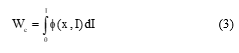
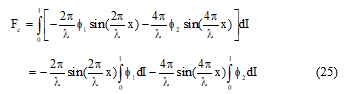
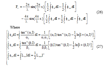
The force developed by a LVRM is relative to the rate of varaition of co-energy as long as the translator changes its position from one position to another. It can be defined as:
![]() Where Fe is the instantaneous electromagnetic force and Wc is the co-energy. The latter can be expressed in terms of the flux linkage, as follows.
Where Fe is the instantaneous electromagnetic force and Wc is the co-energy. The latter can be expressed in terms of the flux linkage, as follows.
 The expression of the co-energy can be substitute in equation (2), which yields:
 2.3. Mechanical equation
Before describing in detail the developed model, it is useful to present the equation governing the mechanical behavior of the linear motor.
The mechanical equation governing the linear motor operation can be given as:
![]() Where m is the mass of the mobile, a is the acceleration, Fe is the developed force, Fl is the load force and is the friction coefficient [11].
Where m is the mass of the mobile, a is the acceleration, Fe is the developed force, Fl is the load force and is the friction coefficient [11].
3. Finite Element Design of LVRM
The developed finite element model is performed according to the geometric parameters of the motor presented in table I.
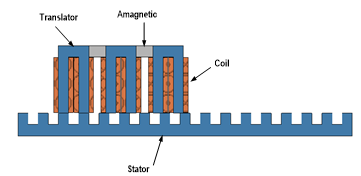 Figure 1. Single sided variable reluctance motor
To achieve a regular operation in step mode, the teeth and the slot widths are chosen equal.
![]() The pole and slot widths are related to the pole pitch by the following equation:
The pole and slot widths are related to the pole pitch by the following equation:
![]() Where is the translator slot width, is the translator pole width and is the pole pitch.
Where is the translator slot width, is the translator pole width and is the pole pitch.
The operation of the variable reluctance motor is based on the principle that the phases are powered independently and only one phase pole must be aligned with the stator poles. Then, to impose a regular step during the operation, a non-magnetic separation between different phases is necessary.
The translator is composed by three similar module separated by a non-magnetic material whose width is determinate by :
![]() With and k =
With and k =
The mechanical step is correlated to the pole pitch and the phases number N by the following equation (9):
![]() The yoke thickness of the stator and the translator are choosing equal to the slot width.
The yoke thickness of the stator and the translator are choosing equal to the slot width.
![]() Table 1: Specific geometry of designed motor
Table 1: Specific geometry of designed motor
| Parameters Value(mm) | |
| Stator pole width 30
Stator slots width 30 Stator yocke thikness 30 Translator pole width 30 Translator slots width 30 Translator yocke thikness 30 Separation 50 No of turns of wdg/phase 350 Section of copper 0.5 Air gap length 0.5 |
The 2D finite elements results obtained by the developed model are used to elaborate a surface response of the thrust force and flux linkage according to the translator positions and different supplying current level Figure 2 and Figure 3.
The simulation results are performed during a mechanical cycle where the moving part translates from the initial aligned position (x=0) to the next aligned position (x=0.06m) going through the unaligned position (x=0.03m).
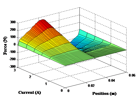 Figure 2 . Force as function of position for different current level
In order to develop a high force, the variable reluctance motor operates in saturation part of the B-H curve of the magnetic material, so it has a nonlinear behavior. The origin of this non linearity is mainly due to the non-linearity of the material used for the construction of magnetic circuits and the salient structure of the studied motor [12].
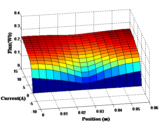 Figure 3 . Flux according to the translator position for different current
To avoid the problem of inaccuracies of the numerical method and in order to achieve a precise model of LVRM, it is recommended to use a methodology that permits to take account the nonlinearity of the magnetic characteristic of the used material while minimizing the simulation time. There are two main analytic modelling of LVRM used in previous work: the flux based model and the inductance based model [13, 14, 15].
In this study, the flux-based model is adopted to determine the static and the dynamic performances of the proposed motor. The proposed model for LVRM can be divided into two parts: a electrical and a mechanical part, they are realized as follows.
4. Analytical Modelling Approach for LVRM
In literature, there are two types of modelling, the linear model and the nonlinear model. Several research studies have adopted either the linear model [13] or the nonlinear model to predict the performance of a variable reluctance motor. The basic concept of this modeling consists of dividing the static flux linkage characteristics into two areas such as the unsaturated region and the saturated region as shown in Figure4. From the flux linkage characteristics, the two analytical models of the LVRM are defined as follows.
In the unsaturated region, when the phase current is lower than the saturation current , the LVRM is defined by a linear model. In the other hand, in the saturated region, when , the LVRM performances can be defined by a nonlinear model.
In the both models the flux linkage is represented by Fourier series and assumed has a cosine function of the position x although. However, in the nonlinear model a great harmonic order in Fourier series is used to give a satisfactory result. Then, it is possible to add another higher harmonics in the proposed model when more accuracy is needed [4].
4.1. Nonlinear Flux Based Model of LVRM
The modeling of variable reluctance machines is more complex than those of alternative current machines because of its highly nonlinear operation. The flux in each phase has a nonlinear function of the position and the phase current, it has a periodic function of translator position with a period of . Consequently, an analytical model for the flux based on Fourier series representation is developed in this part.
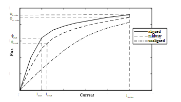 Figure 4. Flux current characteristic for three positions
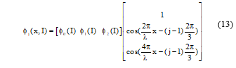
Considering the first three components in Fourier series [7]. The flux in each phase can be represented as:
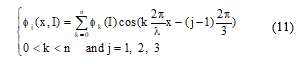 Where n is the number of terms included in the Fourier series and j is the phase index.
Considering the first three components of the Fourier series in Equation (11), the flux expression become:
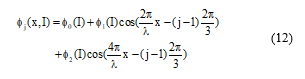 Where , , are the first three terms of Fourier series.
The developed model is written in a matrix form as:
 The matrix model of flux is developed by considering three important positions, the aligned position (x=0), the midway position (x=15mm) and the unaligned position (x=30mm).
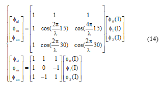 With , and are the flux values for the aligned, intermediate and unaligned positions respectively.
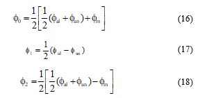
Hence,
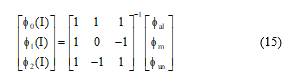 The three coefficients can be computed based on the flux in three positions as follow.
 The flux at the aligned and the midway position is determined by an arctangent function.
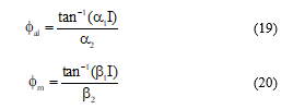 Where , , and are constants that can be calculated by following the steps below:
– Define two points and on the flux curve relative to the aligned position.
The value of the flux corresponds to the maximum current Imax (maximum current), whereas it corresponds to the current Iasat (Saturation current).
-The constant can be determined by using the relation below:
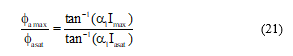 Where is the maximum flux linkage at the aligned position, is the saturated flux, is the maximum current and is the saturated current.
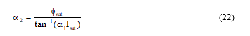
-The constant can be determined as follow:
 -The coefficient and can be calculated in the same way as and by using the suitable data obtained from the flux curve in the midway position.
-Since the saturation effect does not exist in unaligned position, therefore the flux linkage can be approximated by a linear equation.
![]() Where, represent the phase inductance at the unaligned position.
Where, represent the phase inductance at the unaligned position.
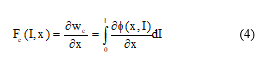
4.2. Computation of Electromagnetic Force
The developed electromagnetic force is proportional to the square of current if the motor is unsaturated (La and Lun=cte), when the current increase and exceeds the saturation current then the electromagnetic force is no longer proportional to only the square of current it can be derived from the co-energy expression.
The flux depends to the translator position and the phase current. Then, the partial derivative of the flux with translator position can be written as:
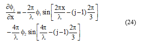 From equation (4), the developed force by one phase of the LVRM is described as:
 By substituting the equations (17) and (18) into equation (25), the expression of the force become.
 5. LVRM Performances Prediction
To validate the model developed, we conducted simulation tests by developing a program designed around the Matlab/Simulink environment and adopting the following parameters:
U=24V, =65Nsm-1, , , , , , m=20Kg and Lun=0.5H.
In this section, the analytic model presented previously is simulated to predict the static and the dynamic performances of the LVRM. Subsequently, the obtained results are presented.
5.1. Static performances
The simulations results shown in this part are obtained basing on the analytical modeling approach described in part 3.
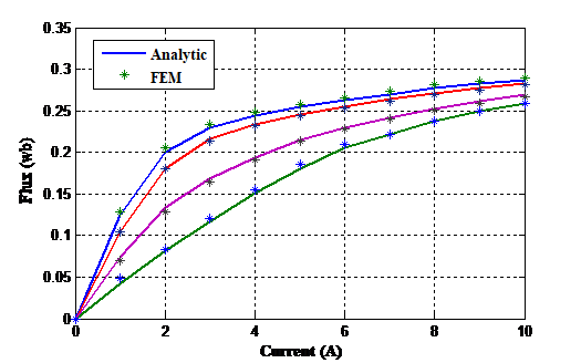 Figure 5 . Comparison between the calculated flux linkage and the FEM
Figure 5 shows a comparison of flux linkage/current characteristics for the designed motor of the analytic model with the result obtained by finite elements method (FEM). The comparison is made at four positions from aligned to completely unaligned position, it shows that the calculated flux is in good agreement with the computed FEM results.
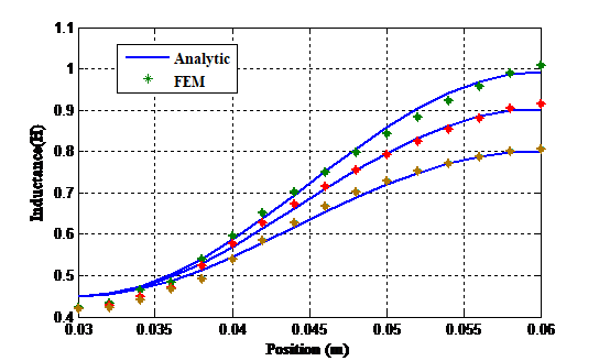 Figure 6 . Inductance as function of position for three current level
Figure 6 show the comparison of the computed magnetizing curves of the LVRM obtained by the proposed model and 2D Finite Element Method (FEM). Each curve of inductance is calculated under the condition that the phase A is excited by a selected current at different translator position. In addition, it is found that the obtained magnetizing curves from 2D FEM almost agree with those from the proposed model, only a slight difference in unaligned position is observed between the results obtained by both methods, due mainly to the assumption of non-existence of saturation at the unaligned position.
The phase inductance varies considerably at the aligned position with the current phase because of the magnetic saturation effect but the inductance at the unaligned position does not very much mainly because of the large reluctance that characterizes huge air gap in the flux path.
The accuracy of the proposed model can be enhanced by the appropriate choice of the number of Fourier terms. Thus, the observed mismatch can be improved by adding another Fourier term in the proposed model.
We can observe from Figure 6 that on the aligned position the values of the inductance vary considerably depending on the current level as the current increases the inductance decrease due to the saturation effect of the magnetic circuit and the inductance is constant at the unaligned position independent of the current value the effect of saturation is negligible.
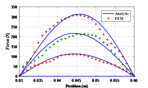 Figure 7 . Static force curve comparison for three current level
The comparative results of static force computed by the 2D FEM and calculated by an analytic model are shown in Figure 7, the comparison is done under the single phase operation at three different supplying currents from 1 A to 3A.
It can be observed from Figure 7, that the profile of the calculated force waveform relatively agrees well with that of the analytic one. Therefore, the validity of the proposed modelling approach is verified.
The developed model is validated from the above static behavior of the motor, so it will be possible to predict the dynamic performance of the motor by the proposed analytic modeling. In the following section, a non-linear dynamic performances analysis of LVRM are described.
5.2. Non-linear dynamic performances analysis :
In order to examine the validity of the proposed model in dynamic operating conditions, the analytical representation of flux is used to define the dynamic model by substituting this expression in the voltage equation. Then, the given model is implemented in Matlab Simulink to establish the dynamic performances of the LVRM and the obtained results has been compared with the FEM results. Therefore, a dynamic analysis based on the analytical model explained in this section.
For the variable reluctance motors, the flux linkage varies as a function of current and position, the phase voltage differential equation for active phase is given by.
Incorporating the flux expression (13) into equation (27), yields,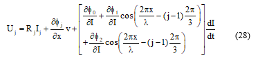
Therefore, the derivative of current can be obtained by calculating the partial derivative of the flux with translator position and the partial derivative of the flux with excitation current as:
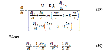
 Figure 8 . Comparison of the computed and FEM phase current
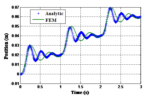 Figure 9 . Comparison of dynamic response of the motor
Figure 8 and Figure 9 present the comparison of the dynamic behavior of the motor. The superposition of these results shows that the dynamic response obtained by both methods admits the same response time with same over shoot, but slight difference noted for the number of oscillations between them. A rather good correlation in the results between the proposed model and FEM is observed.
6. Conclusion
In this paper, a novel non-linear model for a variable reluctance linear motor has been presented and compared with 2D FEM analysis results. This model based on the Fourier series analytical representation of flux linkage taking into consideration the effect of nonlinearity which has been neglected in some work describes its static characteristics. The model requires the motor flux characteristics obtained by finite element analysis.
The validity of the proposed model has been verified by the comparisons with results obtained from 2D FEM analysis. Furthermore, the accuracy of the proposed approach in dynamic conditions has been demonstrated. The developed model proves to be adapted for various uses with different machine configurations.
The developed model is motivated by the accurate performance prediction. In fact, it will be used to elaborate a control strategy for this motor.
Conflict of Interest
The authors declare no conflict of interest.
- I .Mahmoud, H .Rehaoulia, “Design and modeling of open loop components for a biomedical application” International transactions On Electrical Energy Systems, 2016. https://doi.org/10.1002/etep.2204
- F .Daldaban, N .Ustkouncu, “A novel linear switched reluctance motor for railway transportation systems”. Energy Conversion and Management,465-469,2009. http://dx.doi.org/10.1016/j.enconman.2009.10.009
- F R .Salmasi, B. Fahmi, “Modeling switched reluctance machines by decomposition of double magnetic saliencies”. IEEE Transactions On Magnetics, Vol 40, No.3, 2004. https://ieeexplore.ieee.org/document/1298927
- A. Khalil, I. Hussain, “Fourier series generalized geometry based analytical model of switched reluctance machines”. IEEE Transactions On Industry Applications, Vol 43, No.3, 2007.
- A .Lachheb, L .El Amraoui, J. Khediri, “Finite element modelling of linear motor for automatic sliding door application”. International journal of advanced computer science and applications, Vol.7 No.8, 2016.
- B .Fahimi, G .Suresh, J .Mahdavi, M. Ehsani, “A new approach to model switched reluctance motor drive application to dynamic performance prediction control and design”. IEEE Powers Electronics, 1998.
- D. A. Andrade, R. Krishnan, “Characterization of switched reluctance machines using fourier series approach”. 36th Conference Industry Applications, USA,2001. https://ieeexplore.ieee.org/document/955391
- H .Gao, F.R .Salmasi, M. Ehsani “Inductance model based sensorless control of the switched reluctance motor drive at low speed”. IEEE Transactions On Power Electronics, Vol.19, No.4, 2004.
- H.P .Chi, R.L .Lin, J. F. Chen, “Simplified flux linkage model for switched reluctance motors” IE Proc Electr Power Applications, 152 (3), 2005.
- P. Lobato, S .Rafael, J. Pires, “Flux linkage characteristics models for switched reluctance machines”. IECON 2010 – 36th Annual Conference on IEEE Industrial Electronics Society 2010.
- W. Zaafrane, J. Khedhiri, H. Rehaoulia, “Low-cost linear switched reluctance motor velocity and position control”. Journal of Circuits Systems and Computers, 2016.
- M. Alrifai, M. Zribi, R. Krishnan , M .Rayan, “Nonlinear Speed Control of Switched Reluctance Motor Drives Taking into Account Mutual Inductance”. Hindawi Journal of Control Science and Engineering, 2007.
- S. Buja, M. I. Valla, “Control characteristics of the SRM drives operation in the linear region”. IEEE Transactions on Industrial Electronics, Vol.38 No.5, 1991.
- Z. Zhu, Y. Sun, Y. Yuan, “Decoupling control for fual winding Bearingless switched reluctance motor based on improved inverse system method”. Hindawi Journal Mathematical Problems in Engineering, 2017.
- S.Husain, A.Hossain, “Modeling simulation and control of switched reluctance motor drives” IEEE Transactions On Industrial Electronics, Vol 52, No.6, 2005.
- S .Mir, I .Husain, M. E .Elbuluk, “Switched reluctance motor modeling with on-line parameter identification” IEEE Transactions On Industry Application, Vol.34, No.4, 1998.
- J .Fang, Y. Ren, “Decoupling control of magnetically suspended rotor system in control moment gyros based on an inverse system method”. IEEE/ASME Transactions on Mechatronics 2012; Vol. 17, No. 6, pp. 1133–1144, 2012.
- Siadatan A, Torkaman H, Afjei E, “Septic segment switched reluctance machine design modeling and manufacturing”. International Transactions on Electrical Energy Systems, 2016.
- J .Faiz, K M .Zadeh, “Design optimization of switched reluctance machines for starter generator of hybrid electric vehicle by genetic algorithm”. European Transactions on electrical power 2009.
No related articles were found.