Automation System for Regulation Optimization in Power Transformer Design

Adv. Sci. Technol. Eng. Syst. J. 4(1), 1–7 (2019);
 DOI: 10.25046/aj040101
Large power transformers generally include a customer request for a technically appropriate regulation unit. The selection process of the regulation unit consists of defining the required input data, performing mathematical calculations necessary to find the technical limit values that the regulation unit has to satisfy, and finally optimizing and selecting the appropriate regulation unit. The number of possible permutations consists of thousands of different combinations, depending on the type of regulation and other technical limitations. The automation system presented in this paper significantly reduces the time required to obtain the optimal regulation unit solution in both offer and order stages of the project, providing significant overall productivity increase. This paper presents an example of managing a part of a complex system such as power transformer design using a software solution. The process of finding the optimal regulation unit „manually” can take up to several hours. Implementing the developed algorithm and introducing Tap Changer Selection application, the required time is reduced to several minutes. This represents significant time savings and reduced possibility of errors, thus improving the power transformer design process.
1. Introduction
This paper is an extension of work originally presented in the conference Proceedings of the 41st International Convention for Information and Communication Technology, Electronics and Microelectronics (MIPRO 2018) [1].
Large power systems such as electrical grids of entire cities, countries or continents are systems which must be continuously regulated in order to keep the voltage supply constant, thereby ensuring all the electrical devices and equipment to work in the expected voltage range. In such large systems, disturbances in the load and/or supply are inevitable – i.e. under greater load, the current increases, and consequently the voltage drops along the transmission lines which connect the power supply to the power consumption. It is important to emphasize that there are two main types of voltage deviations. The first is caused by a change of load on the lower voltage side of the power transformer. Since load through the power transformer has changed, the change of the position of the regulation unit is required in order to maintain the voltage at a constant level. The second voltage disorder is the case when voltage is changed on the higher voltage side of the power transformer as a consequence of a certain kind of network disturbances [2]. Handling such disturbances and maintaining a constant voltage supply is (among others) the responsibility of the power transformer as one of the most expensive parts of the power grid. For this purpose, the regulating power transformer is equipped with a regulating winding which is connected to the regulation unit – as shown in Figure 1 – usually On Load Tap Changer (OLTC).
The OLTC principle was patented in 1927 by Dr. Bernhard Jansen. Together with the industrial development and economic growth over the years, the overall power consumption took an upward trend, following the expansion of the electrical grid. The development of OLTCs was accelerated over the years due to the steady increase of the transmission voltage and power. The voltage regulation basic principle is adding or subtracting turns from either the primary or the secondary winding. The OLTC alters the power transformer turns ratio in a number of predefined steps and in that way changes the secondary (or primary) side voltage [3].
As opposed to the OLTC, the DETC (De Energized Tap Changer) must not be operated while the transformer is energized. This means that for the DETC to operate, the transformer must be disconnected from the network for a short period of time. Due to the mentioned limitations, the DETC is used only when the regulation capabilities are not a primary concern. This is why an OLTC regulation unit is more and more becoming a standard customer request for power transformer regulation.
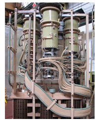 Figure 1: Power transformer with a regulation unit
Generally, many different regulation units are technically appropriate and may be used for a particular transformer design. In order to minimize the overall costs while still managing to provide the required regulation capabilities, one of the transformer manufacturers’ challenges is to optimize the regulation unit selection process. Since the regulation unit (i.e. tap changer) can make around 10 – 20% of the total material cost of the transformer, the overall effect of optimizing the regulation unit becomes significant.
Related work on this area consists of different power transformer design tools which (at most) consist of a regulation unit database, expecting the user to choose the appropriate regulation unit from the list (manually). A tool example presenting automated regulation unit selection functionality in the power transformer industry is ABB Compas tool [4]. Since this tool is limited only to ABB types of tap changers, the main motivation for this work was to provide a faster and more efficient way of selecting the optimal regulation unit also for manufacturers other than ABB, e.g. MR (Germany) and C.A.P.T. (Italy) for OLTC and DETC regulation units since this is a common customer request. The main advantage of this application becomes evident in the offer stage where quick and correct selection of the optimal regulation unit is important for the final transformer design cost estimation.
2. Transformer Regulation
The transformer is an electrical static device without moving parts, used to transform electrical power from one circuit to another without electrical connection and without changing frequency. Transformer switches the alternating current of the predetermined electrical voltage into alternating current of a higher or lower electrical voltage using the effect of mutual induction. The only moving part in a power transformer, the On Load Tap Changer, is one of the main contributors to the failure rates of high voltage power transformers [5]. Taking this into consideration, it makes sense to standardize and automate the regulation unit selection process, which was the main motivation for this work.
The introduction of OLTCs improved the operating efficiency of electrical systems considerably and this technique found acceptance worldwide. In general the percentage of transformers equipped with OLTCs is increasing with the increase of the load density and interconnection of electrical networks. In addition, OLTCs applied in industrial process transformers as regulating units in the chemical and metallurgical industry is another important field of application [6].
Basic connection diagrams for regulation are typically chosen with regard to system conditions and size/weight limits during transportation.
Linear regulation (Figure 2) is applied for a simple design transformer and regulation unit, with regulating range up to 20 percent of nominal voltage. The taps are added or substracted in the series with the main winding. This kind of regulation ensures smallest ohmic losses.
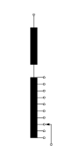 Figure 2: Basic connection diagram linear regulation
For linear regulation, voltage accros tap winding UTV is equal phase to phase voltage across regulation UR.
![]() Most common type of regulation is a reversing change-over selector (plus/minus switching), which allows doubled tapping range. Regulated winding is connected with the basic winding in series (Figure 3). The total number of taps decreases or increases, depending on position of tap selector. Boost and buck connection (boost – vectorial addition to main winding and buck -vectorial substraction to main winding) enables to increase the regulating range or to reduce the number of tapped winding.
Most common type of regulation is a reversing change-over selector (plus/minus switching), which allows doubled tapping range. Regulated winding is connected with the basic winding in series (Figure 3). The total number of taps decreases or increases, depending on position of tap selector. Boost and buck connection (boost – vectorial addition to main winding and buck -vectorial substraction to main winding) enables to increase the regulating range or to reduce the number of tapped winding.
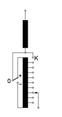 Figure 3: Basic connection diagram with reversing switch
Regulation with reversing change-over selector, for constant induction, depends on regulating voltage and number of step of the tap winding:
![]() Coarse change over selector or coarse/fine switching requires more complicated winding layout – it is regulation with two windings, regulated winding and coarse winding insertion (Figure 4). Arrangement of coarse/fine selector has the electrical length of the fine tap winding plus one step. This kind of regulation offers the lower copper losses in the tap position with the mínimum number of effective turns. Coarse/fine regulation offers for some industrial applications possibility of large number of operations using special design with up to 5 coarse taps (107 operations i.e. operating positions) [7].
Coarse change over selector or coarse/fine switching requires more complicated winding layout – it is regulation with two windings, regulated winding and coarse winding insertion (Figure 4). Arrangement of coarse/fine selector has the electrical length of the fine tap winding plus one step. This kind of regulation offers the lower copper losses in the tap position with the mínimum number of effective turns. Coarse/fine regulation offers for some industrial applications possibility of large number of operations using special design with up to 5 coarse taps (107 operations i.e. operating positions) [7].
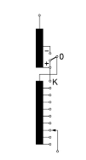 Figure 4: Basic connection diagram with coarse tap selector
Regulation with coarse fine change over selector across tap winding:
![]() Voltage across coarse tap winding UCV=UTV
Voltage across coarse tap winding UCV=UTV
where:
UTV is voltage across tap winding in ;
UR is regulating range phase to phase in ;
UCV is voltage across coarse winding in ;
m is number of steps of tap winding
3. Manual Selection and Calculations
The selection of appropriate OLTC should be made very carefully, because the OLTC is an important factor with respect to the transformer’s reliability and cost. Each type of regulation unit is available in a number of variants, with different values of maximum rated through-current, number of phases, highest insulation level, tap selector size and basic connection diagrams. Therefore, the type designation of a regulation unit depends on these features. A guideline for the OLTC selection is given in IEC 60542, but some special applications as HVDC transformers or phase shifters are not described in detail.
When selecting the appropriate type of OLTC or DETC manually, a number of parameters and technical limits have to be considered.
First of all, the rated through current of the regulation unit must not be less than the transformer highest current value of the regulating winding. For regulation at the neutral end with constant induction (constant flux voltage variation, CFVV), the rated through current in case of a three-phase full transformer is derived using the rated power as the product of current and voltage (one or three-phase).
For a three-phase autotransformer with regulation in neutral end, variable induction (variable flux voltage variation, VFVV),. Sn=const., the rated through current depends on both regulated and non-regulated voltage levels:
![]() where:
where:
U1 is the rated line voltage of the non-regulated side in
U2min is the rated line voltage in the minimum tap position in
In case of one-phase transformer, the rated through current is multiplied by a factor of Ö3 since the rated power is per phase and the rated voltages are phase voltages.
Maximum rated through current is the current which the regulation unit is transferring from one tap to the other at relevant step voltage.
Step voltage Ustep [V] is the phase voltage between the taps which depends on the required regulated voltage range and the required number of positions. This value is constant in case of CFVV (constant flux voltage variation), unlike in the case of VFVV (variable flux voltage variation) where different regulating positions have different volt/turn ratio and therefore different step voltage values:
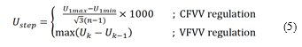 where:
U1max and U1min are the required maximum and minimum regulated line voltage in [kV] (equivalent three-phase bank line voltage in case of a single-phase transformer);
n is the required number of regulating positions (including the rated position);
Uk-Uk-1 is the (phase) voltage difference in [V] in the regulating position k and k-1 (for positions k = 2 to n).
The required regulation unit external insulation level depends on the insulation level to ground of the side where the regulation unit is connected. The withstand voltages of the external insulation are standardized by international standards and correspond to the highest voltage for equipment [8]. In case of regulation in neutral end (common for full transformer or VFVV autotransformer), the insulation level is usually the same as the insulation level of the transformer neutral (unless otherwise specified). In case of regulation in line (common for CFVV autotransformers), the insulation level is the same as the lower voltage side to which the regulation unit is connected. The insulation level has to be checked against the applicable technical guide.
The internal insulation level affects the regulation unit tap selector size, whose price can vary significantly, meaning that the proper selection is of the essence in choosing the optimal regulation unit. Highest operating voltage across the regulating winding is the value that has to be compared with the highest permissible phase service voltage across the regulating winding described in the technical guide, which defines several internal insulation distances to be checked, most important of which are distances ‘a’ and ‘b’. For insulating distance ‘a’ between start and end of the regulating winding and insulating distance ‘b’ between the fine tap selector contacts of different phases, a statistics-based estimation is used. The logic behind the estimation is assuming linear distribution, and additionally applying a „non-linearity“ factor depending on the regulation concept (reg.in main / coarse-fine / reversing / linear) and transformer type (full / auto). The mentioned factor is determined using statistical analysis derived from experimental data. The differences in factors arise from the specifics of the distribution of electrical field in various power transformer types.
With some winding arrangements (neutral-end in autotransformers and line-end regulation in delta connected windings), very high voltages may occur. These voltages are significantly influenced by the choice of the regulation concept (linear, coarse fine or reversing regulation). In such cases, additional tools are used to determine the electrical field distribution in the power transformer (FEM analysis). Since the tap selector size price varies significantly, this can also be subject to optimization.
The switching capacity PStN [kVA] determines the capability of the regulation unit to switch between regulation steps. Since the worst case has to be considered, the required switching capacity in the regulation unit is the product of the relevant step voltage and maximum rated through current (both described above):
![]() The required switching capacity for a specific contact in an OLTC is based on the relevant step voltage and current but is also determined by the design and circuit of the OLTC. The switching capacity itself is primarily a function of the contact design, contact speed and arc-quenching agent [9].
The required switching capacity for a specific contact in an OLTC is based on the relevant step voltage and current but is also determined by the design and circuit of the OLTC. The switching capacity itself is primarily a function of the contact design, contact speed and arc-quenching agent [9].
The selected regulation unit must be within the switching capacity diagram (example in Figure 5). Limit values are given in the manufacturer’s technical guide and may rectrict certain types of tap changers in some cases.
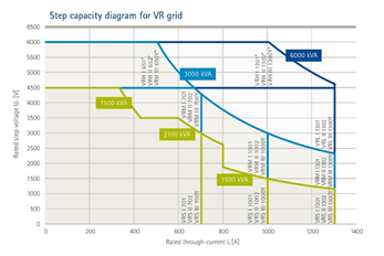 Figure 5: Step capacities diagram
The number of tap positions and the number of contacts have to be considered as well – different types have different maximum regulation range, depending on the regulation concept. A higher number of positions may also increase the voltage stress of the regulating winding, so this has to be taken into consideration (as described in the internal voltage calculations above). For rectifier or furnace transformers, wide tapping range should be considered.
The predicted contact life of fixed and moving contacts is a function of the rated through current and has to be compared with the diagram for a specific regulation unit which can generally be found in the regulation unit manufacturer’s technical guide.
The recovery voltage occurs on the open change-over selector contacts during switching sequence. It depends on the geometric winding arrangement and the capacitances C1 and C2. Recovery voltage can cause switching sparks or low-energy arcs, thereby producing unwanted gas which has a negative effect on the characteristics of the insulation media (usually insulating oil). The recovery voltage and breaking current values have to be checked in + and – selector switch positions:
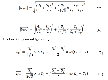 UW+ and UW- are the recovery voltages in [kV];
IS+ and IS- are breaking currents in [mA];
C1 and C2 are the capacitance values in [pF] of the regulating winding (as shown in Figure 6) which can be approximated assuming cylindrical winding system [10].
U1 is the rated regulated voltage in [kV];
Uf is the preselector voltage in [kV];
ω=2πf, where f is the power frequency in [Hz].
Example for recovery voltage calculation for single phase autotransformer with regulation of common winding (Figure 7) in wye connection (fine regulation), input data:
- Rated power: 200MVA
- Rated voltages and relevant tapping range: 400 / 230 +10 x 1,5%, -10 x 1,5% / 24 kV
- Step voltage: 1992 V
- Max. tapping current: 1772 A
Test Voltages:
- a…340 kV (1,2/50μs); 65 kV (50 Hz)
- Um… 950 kV (1,2/50μs); 395 kV (50 Hz)
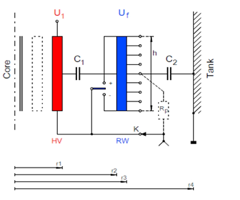 Figure 6: Recovery voltage – capacitances per phase
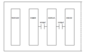 Figure 7: Autotransformer winding arrangement wye connection
According to input data (capacitances C1=4696pF and C2=3366pF), following recovery voltages and breaking current are calculated:
UW+=8,3kV; UW-=28,2kV
IS+=21mA; IS-=71,3mA
According to Figure 8., the potential measure is not needed.
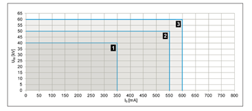 Figure 8: Recovery voltage and breaking current diagram
The recovery voltage permisible value is the function of the calculated breaking current value. The mentioned UW(IS) function for each tap selector type and size can be found in the technical data of the regulation unit. If the calculated values of recovery voltages are exceeded, it is necessary to install tie-in resistors or select a different tap selector. The installation of the tie-in resistors affects the regulation unit price as well as overall transformer dimensions, so a solution with bigger tap selector size and therefore higher permisible values of recovery voltage should be considered in such cases. Furthermore, the tie-in resistor dimensions are defined by the regulation unit manufacturer specifically for each design, which can cause an additional unwanted time delay in the transformer final design process. For phase shifting transformers, using regulation unit with two-way change-over selector, one can overcome problems during the change-over selector operation and change of winding connections between phases of the system voltage [11].
4. Tap Changer Selection Application and Database
Due to the complexity of the regulation unit technical limits and cross-dependencies between different types, a relational database is developed in such an architecture that an algorithm can quickly go though all of the possible permutations and compare the actual calculated values with every combination of regulation unit’s limits. Also, the database management user interface (UI) is developed in MS Access environment. Within the database, SQL is used for querying data and sending it to the application for further analysis in the TCS algorithm (Tap Changer Selection). The algorithm then compares the queried data with the calculation results which are calculated in the background as thoroughly described in chapter III. The algorithm also takes into account different possibilities of transformer regulation: for example, a three phase transformer can either be regulated with a single three-phase regulation unit or three single-phase regulation units. Furthermore, autotransformer can be designed with regulation in main winding, meaning that the regulation unit does not have a common neutral end. Therefore, autotransformers with such regulation can only be regulated with three single-phase regulation units (three-phase regulation unit requires a neutral end common point). Also, different regulation concepts have different possibilities for number of positions and number of contacts.
All of the mentioned above is automatically checked for every single regulation unit combination queried from the database. This is achieved using a foreach loop which (in each step) calls for different modules used for this purpose. All of the modules and functions are developed in C#, following object-oriented software development principles (Model-View-Controller, MVC pattern). The input for the algorithm that is expected from the application user is the same data that the electrical designer uses in power transformer design (MVA rating, rated voltages and required regulation range, regulation concept, connection of regulating winding, LI and AC voltage levels i.e. external insulation levels to ground and number of tap positions), making the application very user-friendly for any power transformer designer. This data model also makes automatic data import from transformer design software very simple. The algorithm output is the list of all the possible solutions for regulation units (tap changers) that satisfy the given input.
The results are finally sorted according to the expected total cost, as shown in Figure 9. Therefore, the application user can simply choose the first regulation unit from the generated list knowing that this is the optimal solution. Other regulation units from the list are not optimal but are also technically acceptable. These can be selected in case of a specific request (e.g. higher external insulation level requested by the customer). Finally, a report containing all the calculations together with the technical limits can be generated automatically.
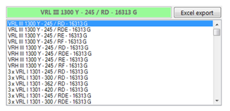 Figure 9: TCS results
4.1. Web application
Together with the Tap Changer Selection application, an additional tool (Figure 10) is developed for accessing the final order data through a Web interface.
The RSB Base application allows reading all the necessary technical data from the ordering data sheets, saves this data to the database and gives the possibility to search, analyze and report through user-friendly interface.
Features and functions of the MVC WEB application and the database:
- Tables
OLTC data loaded from ordering documenation, gets entered into the database tables. An intuitive UI provides an organized way to represent the data. Tables contain all necessary fields from ordering documentation as well as coded tables for data analyzing and reporting.
- Forms
Application provide functionality with controls that allow inserting new ordering data, editing, deleting, page through, sort, filter and search tables and queries, modify ordering data, as well as creating reports.
- Reports
The application allows the user to manipulate stored data in various ways. One can use application’s built-in function for creating reports to help in analyzing the OLTC data, e.g., calculation of motor drive equipment and electronics in detail.
- Data functions
Application software provides features to organize data (CRUD – Create Read Update and Delete) and functions for sorting, filtering, reporting etc.
5. Results and Future Work
Possible future work includes improvements by developing a faster OLTC search algorithm. The database contains all the necessary technical information about the offered and executed projects. The current available size is approximately 400 items with more than 90 properties (with a growth tendency). By increasing database and displaying equipment in the motor drive unit in detail, the possibility to make a mistake in the transformer design offer stage is already significantly reduced. In TCS application, different simplifying estimations were made (depending on the regulation concept, linear distribution and nonlinear factor were applied) which are still acurate enough to select an OLTC properly. There is room for expansion in the application in order to better cover some special transformer’s designs, such as HVDC, limit cases or arrangement with enforced current splitting. However, the results are already visible in the offering phase, by reducing the time of OLTC selection up to 90% compared to the manual selection. This means a lot of working hours in the design office have been saved. Further improvements are reflected in the pooling data from application database itself and from the web application that is related to the OLTC and motor drive unit equipment ordering data in one general database.
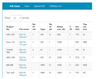 Figure 10: Web interface – homescreen
6. Conclusion
The importance of regulation in power transformers shows that optimizing and choosing the appropriate regulation unit may have a significant impact on the transformer overall cost, making it one of the essential parts of power transformer design. Management of such a complex system by implementing a software solution is presented in this paper. Comparison with Compas tool is not entirely possible, because TCS application works with types of OLTCs and DETCs other than ABB. It could be said that TCS and Compas largely cover all the needs of the transformer manufacturer for the appropriate regulation unit. In TCS application, dozens of tables and diagrams, as well as hundreds of pages of technical data from different manufacturers are incorporated in the database. Nevertheless, the developed algorithm performs all the calculations and searches through all of the possibilities in a matter of seconds, regardless of the regulation unit manufacturer. This represents significant time savings and reduced possibility of errors, providing productivity improvement in power transformer design process. Selection of OLTC is a critical point in the transformer design process due to a large number of correct solutions, only one of them being optimal while also technicaly acceptable and cost-effective. It can be concluded that the TCS application connects the physical properties of the OLTC and the information technology, which has led to material and time savings in transformer design process
Conflict of Interest
The authors declare no conflict of interest.
- M.Gazdović, T.Šimović, “Digitalization of Regulation Unit Selection Process in Power Transformer Design” Proceedings of the 41st International Convention for Information and Communication Technology, Electronics and Microelectronics (MIPRO 2018).
- G.Leci, A.Marušić “Koordinirana regulacija napona energetskih transformatora” 11. savjetovanje HRO CIGRÉ, 2013.
- IEC 60214-2 Tap-changers – Part 2: Application guide, 2004
- ABB, Tap-changer selection program Compas [Web]
http://new.abb.com/products/transformers/interactive-tools/tap-changer-selection-program-compas - R.Levi, “On Load Tap Changer Condition Assessment Using Dynamic Recording and Measurement (DRM)”, 2017.
- A.Krämer, “On-load tap-changers for power transformers,” Maschinenfabrik Reinhausen, 2000.
- Maschinenfabrik Reinhausen GmbH “TD – General Section”, 2003.
- IEC 60076 – 3 Power tansformers – Part 3: “Insulation levels, dielectric tests and external clearances in air”, 2013.
- D.Dohnal, “On-Load Tap-Changers for power transformers,” Maschinenfabrik Reinhausen, 2013.
- M.Gazdović, “TCS help”, Konćar Power Transformers, 2017., unpublished.
- T.Šimović, M.Stanić, L.Kirchner, “200 MVA phasphase-shiftingotransformer for HE Senj and the possibility to change-over between active and reactive power flow control in energized state“, 4rd International Colloquium “Transformer Research and Asset Management”, May 10-12, 2017.
No related articles were found.