Enhanced Ship Energy Efficiency by Using Marine Box Coolers

Adv. Sci. Technol. Eng. Syst. J. 3(6), 83–88 (2018);
 DOI: 10.25046/aj030608
Climate change, increasing fuel oil prices and new international regulation on ship emissions lead to more focus on shipping fuel consumption and energy efficiency. There are various solutions for improving the ship energy efficiency. In this manuscript, we aim to present a real case of energy saving by adopting the central cooling system with box cooler on the ship instead of conventional system. The electric energy power necessary for operating the machinery cooling system of the ship is calculated for conventional cooling system and compared to the cooling system using box coolers in term of fuel oil consumption and CO2 emissions. This study quantified the fuel saving potential that could be achieved with use of keel coolers. Adopting central cooling with box coolers may contribute in reduction of fuel oil consumption and improving the ship energy efficiency. systems. should not contain citations.. The cooling system is designed to covers machinery cooling needs when most of the equipment are in operation at its maximum powers. Safe margin is also added.
When we look at the electric energy balance of various types of ships we notice that cooling water pumps are among the largest and the most equipment running over the time, since they are solicited either when the vessel is at sea or alongside. Therefore, cooling pumps are the largest electric power consumers on board and are accounted for 10% of the kilowatt- hour consumed.
This fact explains why several researches dedicated to ship energy efficiency focus on cooling system components. These studies have focused mainly on improving the performance and efficiency of the conventional cooling system (piping and sea water pumps) i.e. [2,3,4,5] studies on energy saving by improving the pumping system, [6] diagnosis and corrosion protection, [7] cooling system reliability.
Very few studies discussed the possibilities of elimination of sea water pipes and pumps from cooling system [8]. The use of box or keel coolers is one of the solutions available for the ship building industry.
Adopting box coolers for cooling systems allows to eliminate the pumps, filters, valves and reduces the piping length therefore the installation is more simple and cheaper. In addition, elimination of these components will reduce also the cost of the operational maintenance.
This paper aims to demonstrate the effect of box cooler use on ship energy efficiency hence after this introduction we give an overview of different ship cooling systems in section II, in section III box and keel coolers principles are described, in section IV we study an application of box cooler for real ship in operation. Conclusion is given in section V.
2. Ship machinery cooling system:
There are three basic types of cooling system commonly used in the marine machinery on board the vessel.
1-Direct cooling system with sea water (Fig.1): sea water is used as cooling media for heat exchangers in open circuit. Sea water is rawen from sea and pumed directly through the machinery system before being discharged overboard.
The inconvenient of this system are:
-The sea water temperature must be below 50oC to avoid scale formation.
-contamination of the water supply with consequent deposition inside the piping and cooled equipment.
– the system is subject to high rate of corrosion and erosion due to the nature of sea water.
2-Indirect cooling system with freshwate (Fig.2): machinery components are cooled by treated fresh water in a closed circuit. This fresh water is pumped through sea water coolers where its cooled by sea water.
This system reduces the length of sea water piping inside engine room and thus eliminates the corrosion problems linked to sea water. Furthermore, sea water pipes may be made from brass with limited costs.
Also, fresh water as cooling media permits the use of plate cooler instead of tubular cooler for their efficiency and easy maintenance. Figures 1&2 illustrate the simplified drawings of the two conventional cooling systems respectively direct and direct. Only main components are shown.
3-Keel / box cooler based cooling system: In this system, the cooling fresh water is cooled in coolers fitted outside the engine room. Sea water cooling pump and pipes are eliminated. This system is further explained in next chapters.
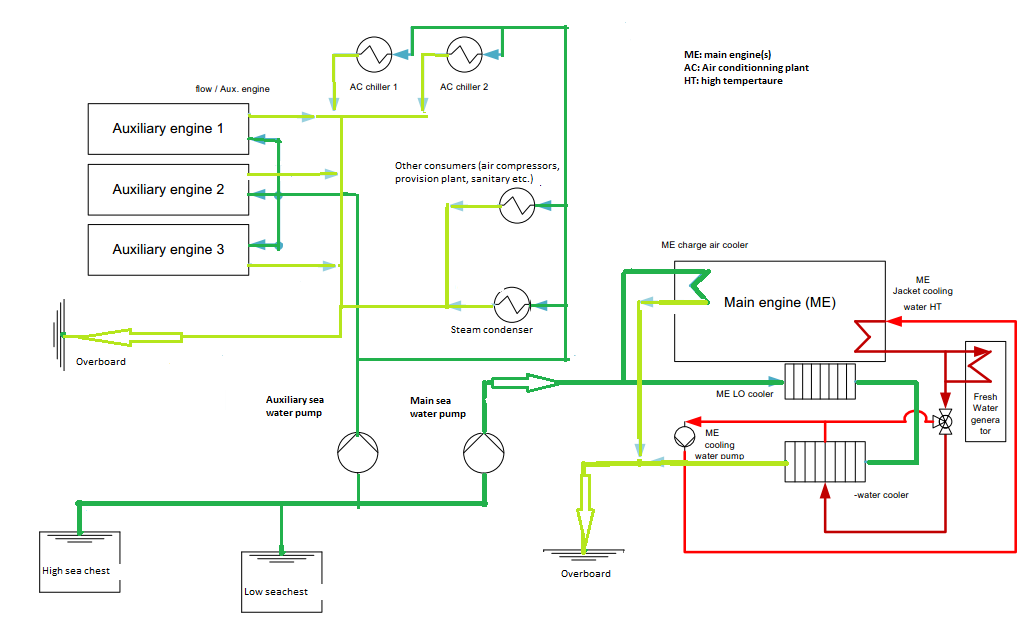 Figure. 1. Direct cooling system with sea water.
3. Description of keel cooler and box cooler.
The terms box cooler and keel cooler refer to the heat exchanges mounted on the underside of ship outer shell or in sea chests under the water line, saving space in the engine room.
Box cooler is a vessel cooling system, in the form of U-tube-bundle (Fig.3 and Fig.4) that is fitted in a sea-chest (Fig.5) on the side of the vessel. The sea chest is equipped with inlet and outlet-grids for circulating cooling sea water. The heat exchange takes place in the sea chest by natural convection of the water when the vessel is stationary or by a circulation due to the speed of the vessel.
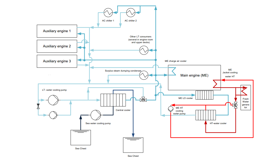 Figure 2. Indirect cooling system with fresh water.
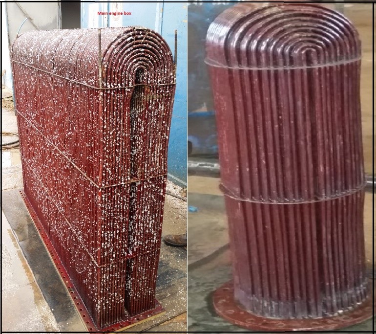 Figure. 3. Box cooler: Main engine (left), Auxiliary engine (right). Photos taken during the vessel “ASD” stay in dry dock (2017).
Keel cooler (Fig.6): The closed circuit of fresh water is pumped in the spiral tubes installed outside the ship’s hull below the water line, its contact with the sea water ensures the heat transfer and achieving the cooling effect. Compared to conventional cooling systems, a keel / box cooling system provides several advantages.
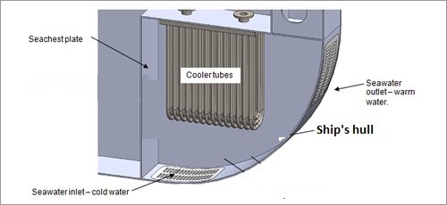 Figure 4. Box cooler and sea chest. (Google image).
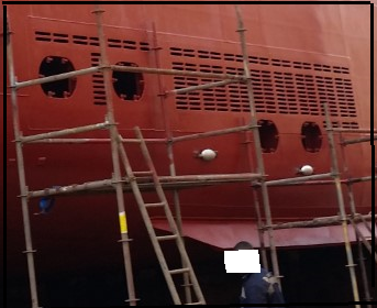 Figure 5. Sea chest where box coolers are fitted (“ASD” at dry dock 2017).
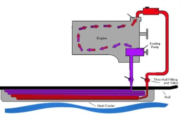 Figure 6. Basic keel cooling system. (Google image).
The sea water pumps, filters, sea water piping are eliminated, operational cost for cleaning, repairing and renewing the system components are reduced. It can also operate in all sea water conditions: icy, silt or polluted. However, the use of box and keel coolers raises some challenges, mainly the material corrosion and the biological fouling.
Nowadays the corrosion caused by box coolers may not a big problem due to technological advances in manufacturing resistant materials. The coolers are fabricated from noble materials such cooper alloys deemed corrosion resistant. The galvanic effect caused by material difference between the ship’s hull made from steel and coolers is overcame by coating the sea chest surface and in some case by ICCP.
The biological fouling by barnacles, algae and other shellfish depends on the area where the ship is trading and operational conditions. Nowadays several solutions exist to prevent this problem: antifouling coating, electrolytic, chemical injections etc.
The use of box coolers is also limited by its capacity, according to makers, existing box coolers in the market may be used for cooling engines with output up to 30,000KW. Most of the commercial ship are fitted with engine of less power than this limit.
4. Case study
For this paper, we take for study the machinery arrangements of the vessel “Aline Sitote Diatta (ASD)”, this vessel is a “Car Ferry” type used for the transport of passengers and vehicles between ports in Senegal. The particulars of this vessel are summarized in table I.The vessel is car ferry type fitted with two four strokes main engine (ME) with rated power of 1800 Kw each.
The electric power is produced by three sets of diesel generators 433 KW each. One generator can supply all necessary power during normal seagoing. The ship is equipped with two air conditioning units for all accommodations: passengers and crew cabin etc.As fuel, the ship main engines and auxiliary engines are burning marine diesel oil.
Table 1: The ship’s particulars.
| Length | 76 meters |
| Speed | 14.5 Knots |
| Gross tonnage | 3481 |
| Main engine output | Two diesel engine 1800 KW each |
| Propeller type | Controllable pitch propeller |
| Capacity | 504 passengers, 28 vehicles |
Figure 7 is a simplified representation of the machinery cooling installation on board the vessel “ASD”. Set of box coolers are fitted in sea the chests on both sides of the ship. Each engine water coolant (fresh water) is circulated by engine cooling pump through one box cooler, where the coolant is further cooled by sea water before returning to the engine. Heat transfer is achieved by natural convection and circulation due to ship movement.
Compared to figures 1and 2, we can notice that main engine sea water pump and auxiliary engine pumps are eliminated including associated piping, valves and strainers.
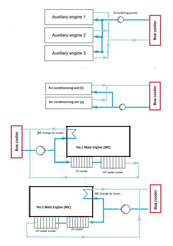 Figure. 7. Simplified represenation of the cooling diagram of the vessel “ASD”.
4.1. Cooling system parameters calculation:
Determination of the sea water flow:
The quantity of sea water ( ) expressed in cubic meter per hour (m3/h) necessary for cooling a single diesel engine is defined by formula (1).
![]() Where
Where
: Heat rejection of Diesel Engine in KJ/h
: Specific heat of sea water = 3.925 KJ/Kg˚C.
⍴: Sea water density = 1027 Kg/ m3
: Difference between the inlet and the outlet temperature of engine sea water cooling.
As per the engine specification published by the Maker, the total heat rejection ( )the case study engine is [9]: Jacket cooling water, Hight Temperature (HT) circuit (375 KW); Charge air cooler, Low temperature (LT)-circuit (607 KW); Lubricating oil, LT-circuit (270 KW).
Note: Due to soft scale deposit inside the sea water piping and coolers which affect the water flow and cooler efficiency, the sea water cooler outlet temperature is generally maintained below to 50˚C. Taking in consideration that sea water temperature in certain navigation zones is up to 36˚C, we take ≈ 14˚C.
By substitution into formula (1) we can calculate the volumetric rate of sea water flow necessary for one engine cooling needs which is approximatively ≈ 80 m3/h. The ship is fitted with two main engines. The ship is also equipped with three auxiliary engines for electric power generation but in worst case only two engines are sufficient to cover the ship power needs. Based on the auxiliary engine technical data, the sea water cooling flow necessary for cooling two auxiliary engines running in parallels is ≈ 30 m3/h.
As the ship is intended for passenger transport the air conditioning plant is important and its capacity is considerable hence the sea water flow required for the AC condenser as per its specification is 20 m3/h.
The total cooling sea water flow is the sum of:
(2×80+30+20) m3/h
Taking safety margin as 10%, The total sea water rate necessary for cooling the machinery at full load is approximately 230 m3/h.
Sea water pump power:
As per Bernoulli equation, the hydraulic power ( ) (expressed in watt) transmitted to the sea water as it passes through the pump is calculated by formula (2)
![]() Where
Where
is the sea water rate in m3/s, ρ is the density of sea water ( kg/m3 at the sea surface), is the total manometric height of the pump and g is acceleration due to gravity, average =9.81 m.s-2).
The total manometric height is defined by formula (3):
![]() : pump suction pressure, in Pascal (Pa)
: pump suction pressure, in Pascal (Pa)
: pump discharge pressure, in Pascal (Pa)
: geometrical height of the pumped medium lift, in meter (m)
: head overall loss, in meter (m)
The difference in dynamic heights is negligible.
includes all losses due to friction inside piping, flanges and valves. Its value depends on the fluid velocity, piping material, piping geometry etc.…
Sea water pump discharge pressure is globally around 2.5 bars (total .≈25m), based on data published by marine diesel engine makers. By solving the equation (2) we define the hydraulic power absorbed by the pumped sea water flow of 230 m3/h.
p.≈ 16 Kw.
The sea water pump is driven by an electric motor, the electric motor power (P) is obtained from formula (4).
![]() – ɳm: pump efficiency, sea water pump is a centrifugal type. The average efficiency for such pump is 60%. [10]. ɳe: is the efficiency of the pump electric motor approximatively 90%.
– ɳm: pump efficiency, sea water pump is a centrifugal type. The average efficiency for such pump is 60%. [10]. ɳe: is the efficiency of the pump electric motor approximatively 90%.
From formula (4) we defined the electric power necessary for driving the cooling sea water pump P= 16/06×0.9 ≈ 30Kw, equivalent to 1.7% of the main engine output. The specific fuel oil consumption for the modern four stroke engine at optimal service conditions is [7,11]:
SFOC = 200 -210 g/Kwh.
Therefore, eliminating sea water pump means saving 150 kg of fuel oil. This is equivalent to 450kg CO2 emission prevention per day. Considering that main engines are used for an average of 260 days per year, the total fuel oil save per year is 39 tons and 117 tons of CO2 emission prevention. The average price of marine fuel oil is 500 $/ton [12]. The application of box cooler for the cooling system of the vessel under study permits to:
-enhance the ship energy efficiency, by reducing the fuel oil consumption and CO2 emissions.
-reduce the ship operational cost.
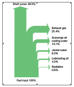 Figure. 8. Energy balance for typical marine diesel engine
4.2. Typical diesel engine energy flux and cooling system energy
The transformation of chemical energy to mechanical work by burning fuel oil is subject to various heat losses. The diagram in Figure 8 also called Sankey diagram, illustrates the basic energy balance of a modern Diesel. The heat losses by cooling engine lubricating oil, engine cooling water and the exhaust gases are mainly produced by the irreversibility of the engine cycle and only part of the energy is transformed into useful mechanical work.
The diagram in Figure 6, also called Sankey diagram, illustrates the overall energy balance of a modern Diesel engine, the values shown on the diagram are an average, slight deviations are possible depending on engine category, type, and power. Globally, the heat losses in marine diesel engines are estimated to 26-30%, this amount needs to be absorbed by the cooling system mainly with sea water.
Taking in consideration that the most used type of fuel for ship bunkers is the heavy fuel oil having a lower calorific value (LCV) of 42,700 KJ/Kg at ISO conditions. The specific fuel oil consumption for the modern two stroke engine is better than for the four-stroke engine.
SFOC = 160 g/Kwh.The actual measured values for various engines is within range of 185- 205.
The input quantity of chemical energy necessary per KWh output is given by formula (3).
The total fuel energy consumed by the engine per hour (input) is given by:
: the engine power transmitted to propulsion shaft (output). The heat losses to be evacuated by the cooling system is within 26% – 30% of (KJ/h). Figure 8 as example.
≈ 26-30% Qt
(KJ/h) ≈ (26 – 30) % (0.160 x 42700 x P)
The heat to be dissipated in Kw is equal to /3600
From formulas (3) and (4) we can assume that the quantity of heat losses (in KW) to be dissipated by cooling system may reach up to 60% of diesel engine output. The cooling sea water rate and the electric power necessary for its pumping are defined by equations (1) and (2).
Table II is extracted from engine specification [11] it shows the cooling water capacity and power for modern diesel engines with different outputs. The column 5 is calculated based on SFOC of 200 g/Kwh, the optimal value for diesel generators. The table II covers only the main engine cooling system. The ship cooling system must be designed for also the auxiliary machinery components: diesel generators, steam condensers, cargo plant, air conditioning etc. The sea water flow and the pump capacity are higher than the values indicated, the fuel oil save and emissions preventions as well. Table II shows that the cooling sea water pump for single engine may absorb up to 0.4% of the engine output.
Depending on the size of this machineries, cooling system power needs may reach up to 1.7% as per the case studied.
Table 2: Propulsion power X Cooling power
| Engine output (KW) | Heat dissipation (KW)
(Maker data) |
Cooling pump capacity (m3/h) | Cooling pump power (KW) | *Equivalent Fuel consumption per day for cooling (kg) |
| 29000 | 17230 | 850 | 110 | 528 |
| 40670 | 24080 | 1177 | 153 | 735 |
| 58100 | 34480 | 1680 | 217 | 1042 |
| 81000 | 48000 | 2400 | 310 | 1488 |
World fleet outlook; Fuel oil consumption:
Table 3 is an extract from “DNVGL” report on 2030 world fleet outlook [14]. The total world marine fuel oil consumption is estimated to 325 Million tons per year equivalent to 1.028 Million tons of CO2 emissions.
Table 3: World fleet X Fuel oil consumption
|
Ship’s type |
Number of ship | Max. engine power | Average engine power | Average consumption per year (in tons) |
| Crude | 2037 | 36,941 | 15000 | 10760199 |
| Products | 5272 | 20,080 | 2390 | 7242117 |
| Chemical | 3895 | 14,758 | 4185 | 14469811 |
| LPG LNG | 1725 | 39,902 | 8252 | 11293652 |
| Bulk | 7392 | 30,099 | 7830 | 49570494 |
| General cargo | 18473 | 16,550 | 2270 | 31986087 |
| Container | 4138 | 80,911 | 21880 | 63722049 |
| Ro-Ro – Ferry | 8859 | 52,799 | 4660 | 34889212 |
| Cruise – Yacht | 1550 | 75,627 | 6710 | 5945856 |
| Offshore | 5086 | 45,199 | 3821 | 4564645 |
| service | 17303 | 82,510 | 2162 | 14041725 |
| Miscellaneous | 24516 | 49,910 | 1060 | 15647195 |
| 100246 | 280965660. |
Total fuel oil consumed by shipping sector is evaluated to 325 million tons, 281 for propulsion and 44 consumed by auxiliary engines.
Reduction of 0.5% of fuel consumption by adopting box cooler means saving 1.6 million tons of fuel oil yearly. From the same table, we notice that less than 3% of ships have propulsion power of more than 30,000KW therefore 97% of world fleet may be fitted with central cooling based on box coolers.
5. Conclusion
The machinery cooling system of the vessel “Aline Sitoe Diatta” was studied. Two cases where considered, use of conventional cooling system and application of box cooler. Both cases are compared for energy efficiency and fuel oil consumption. The main conclusions are:
The ship cooling sea water pumps are the largest auxiliary pumps on board and are running most of the time therefore there are the largest electric power consumers, up to 10% of ship’s needs in kilowatt – hour. For single engine, cooling water pumps absorbs as a minimum 0.4% of the engine output.
In the case studied cooling system of all main and auxiliary machineries requires up to 1.7% of the propulsion engine power. In the opinion of authors, the use of the keel or box coolers for ship machinery cooling system may contribute to reduce fuel oil consumption of the ships, to improve the energy efficiency accordingly and meet the legal requirements [13].
The application of box cooler is limited to small size ships but further to recent technology developments it’s possible to adopt on ships up to 30,000 KW (only 3% of the world cargo vessel is equipped with engine of more than 30,000 KW, mainly container vessels).
With large power, the box coolers may be part of the solution which will contribute to reduce the size and the cost of the cooling system and energy consumption.
- C.T. Wilbur “Pounder’s Marine Diesel Engines” Sixth 6th edition.
- Chun-Lien Su, Wei -Lin Chung, Kuen-Tyng Yu. « An enegy saving evaluation method for adjustable frequency drives on sea water cooling pumps on ships. Industrial and commercial Power system techniques. 2013/ IEEC/IAS 49th
- Gazi Cocak, Yalcin Durmusoglu “Energy efficiency analysis of a ship’s central cooling system using variable speed pump”. Journal of Marine Engeneering and Technology: Published on 2017-01-31.
- Mia Elg, Maunu Kuosa, Markku Lampinen, Risto Lahdelma, Panu Mäkipeska, Juuso Raita, Guangrong Zou, Kari Tammi “Advanced auxiliary cooling system for energy efficient ships”. Technical Research Centre of Finland Ltd. -C._T._Wilbur
- Gerasimos Theotokatos, Konstantinos Sfakianakis and Dracos Vassalos. “Investigation of ship cooling system operation for improving energy efficiency” Department of Naval Architecture, Ocean and Marine Engineering, University of Strathclyde, G4 0LZ, Glasgow, UK.
- Application of titanium in shipboard sea water cooling systems. Wayne L. Adamson Vol.99, Issue 3.
- Ait Allal Abdelmoula, Khalifa Mansouri “Toward a reliable sea water central cooling system for a safe operation of autonomous ship”/ ENSET Mohammedia, University Hassan II Casablanca.
- Andrzej Młynarczak. Box coolers as an alternative to existing cooling systems Scientific Journal. Maritime University og Szczein . 2013, 36(108) z. 2 pp. 131–136.
- Wartzilla 20 product guide. Issue 1/2017
- Sulzer_Centrifugal_Pump_Handbook,_3rd_Ed.M.
- MAN B&W S90ME project guide ed. 05/2014
- https://bunkerindex.com/
- (2011). Resolution MEPC.203(62), Amendments to the annex of the protocol of 1997 to amend the international convention. http://www.imo.org/en/KnowledgeCentre/IndexofIMOResolutions/Marine-Environment-Protection-Committee-(MEPC)/Documents/MEPC.203(62).pdf
- World fleet MACC 2030 Ver.24 DNV. 2012-02-12 GL Library..
- DNV GL SE, (2015). Rules for Classification and Construction, I-1.2, July 2015, Hamburg, Germany DNV.GL website publication 2017.
No related articles were found.