Improved DTC Control Strategy of B12 Inverter Fed BLDC Motor Drives Considering Commutation Torque Dips

Adv. Sci. Technol. Eng. Syst. J. 3(5), 427–438 (2018);
 DOI: 10.25046/aj030549
In most industrial high-power applications, the brushless DC (BLDC) motor is connected to multi-level inverters specially the three-level NPC inverters (B12). Torque ripple is a critical issue in BLDC motor drives. Accordingly, minimizing the ripple produced in the torque is necessary to enhance the BLDC motor drive performances. This paper aims to develop two direct torque control (DTC) schemes. To evaluate the proposed strategies performances, three DTC schemes, namely DTC- 1, DTC- 2, and DTC-3, are treated. The DTC-1 scheme is inspired from the Takahashi’s strategy proposed in induction motor drives. This scheme is penalized by the high torque dips. In view of that, the DTC-2 is proposed to address the DTC-1 limitations. Simulation evaluation proves that difference between the slopes of the incoming and outgoing phases currents procreates commutation torque dips penalizing the DTC-2 scheme. This difference is more serious at high speed. To overcome the DTC-2 strategy drawbacks, a DTC-3 scheme, based on the compensation of this difference, is proposed. Taking into account the increase of this difference with the increase of the rotation speed, the vector selection table design of this strategy is synthesized to minimize the torque ripple as far as possible.
1. Introduction
The use of three-level NPC (B12) inverter in high power applications increases due to their performances [1]- [2]. Indeed, compared to the two-level inverter, the B12 inverter offers the low output current distortion and operates with reduced dv/dt stress [3]-[6].
Due to its numerous advantages as its simple structure, low noise, good stability and high efficiency [7]-[8]-[9], BLDC motor is extensively used in numerous industrial applications. Conversely, the torque ripple is a critical issue in BLDC motor drives [10]-[12]. Accordingly, minimizing the ripple produced in the torque is necessary to enhance the performances of BLDC motor drive system [13]-[14].
The present paper proposes two DTC strategies dedicated to the BLDC motor fed by three-level (B12) inverter. It has been found that commutation torque ripple is a main problem penalizing the first proposed strategy. This commutation phenomenon affects the industrial applications needing high performance [15]-[16]. It leads to a deteriorating efficiency of the BLCD motor. Hence, the second proposed strategy aims to address these drawbacks.
23
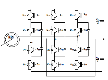 Figure 1: B12 inverter with BLDC motor connected.
2. Analysis of the BLDC motor operation
The B12 inverter is connected with BLDC motor as illustrated in Figure.1
The rectangularly shaped currents(ia, ib, ic) fed BLDC motor are synchronized with the trapezoidal back-EMFs(ea, eb, ec) to accomplish a constant torque with reduced dips as shown in Figure.2.
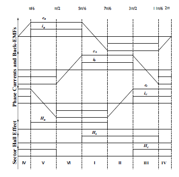 Figure 2: Back-EMFs, phase currents and the corresponding Hall-effect signals of BLDC motor .
The BLDC motor stator voltages (va, vb, vc) are given by: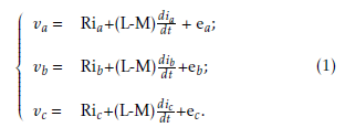
Where:
• Resistance: R (Ω),
• Self inductance: L(H),
• Mutual inductance: M(H).
The produced torque Tem is given as: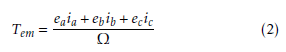
Tem = e aia +ebib +ecic (2)
Ω
Where Ω represents the angular speed.
Under two-phase conduction mode, the B12 inverter engenders six Half voltage vectors (V1 to V6) and six Intermediate Voltage Vectors (V7 to V12).
Under three-phase conduction mode, the B12 inverter generates three null vectors (U01 to U03), six Intermediate voltage vectors (U1 to U6) and six Full Voltage Vectors (U7 to U12).
Tables.1 and 2 provide the switch state combinations.
( Sa Sb Sc) Vα Vβ Vectors
Half Voltage Vectors
(1100 0000 0000) Vdc 0 V1
(0000 0000 0011) Vdc Uc V2
(0000 1100 0000) Vdc Uc V3
(0011 0000 0000) Vdc 0 V4
(0000 0000 1100) Vdc Uc V5
(0000 0011 0000) √1 Vdc 24 Uc V6
Table 1: Active voltage vectors under the two-phase conduction mode.
(1100 0000 0011) q
Vdc Vdc V7
(0000 1100 0011) 0 Vdc V8
(0011 1100 0000) q
− 3Vdc
8 Vdc V9
(0011 0000 0011) q
− 3Vdc
8 Vdc V10
(0000 0011 1100) 0 Vdc V11
(1100 0011 0000) q
Vdc Vdc V12
Intermediate Voltage Vectors
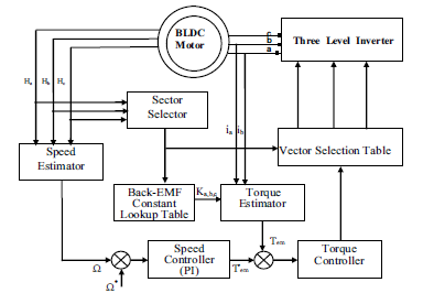 Figure 3: DTC scheme of the B12 inverter with BLDC motor connected.
3. Control strategies
3.1 DTC-1 strategy
The DTC-1 scheme is inspired from the one proposed by Takahashi in [17]. This strategy allows a direct control of the BLDC motor torque.
The DTC-1 scheme block diagram is illustrated in Figure.3. This diagram includes an hysteresis torque estimator which generates two outputs used to determine the vector selection table(cτ = +1:torque increase, cτ = −1:torque decrease).
The switching table of this strategy is summarized in Table 3.
Table 2: Active voltage vectors under the three-phase conduction mode.
( Sa Sb Sc) Vα Vβ Vectors
Intermediate Voltage Vectors
(1100 0010 0011) q
Vdc Vdc U1
(0100 1100 0011) 0 Vdc U2
(0011 1100 0010) q
− 3Vdc
8 Vdc U3
(0011 0100 0011) q
− 3Vdc
8 Vdc U4
(0010 0011 1100) 0 Vdc U5
(1100 0011 0100) q
Vdc U6
Full Voltage Vectors
(1100 0011 0011) q
Vdc 0 U7
(1100 1100 0011) √1 Vdc 6 √1 Vdc 2 U8
(0011 1100 0011) Vdc Vdc U9
(0011 1100 1100) q
− 2Vdc
3 0 U10
(0011 0011 1100) Vdc Vdc U11
(1100 0011 1100) Vdc Vdc U12
3.2 DTC-2 strategy
It has been found that DTC-1 scheme is penalized by the high torque dips. In view of that, the DTC-2 is proposed to address the DTC-1 limitations. The control scheme of this strategy is similar to the one used in the DTC-1. The only difference is the control rules considered in the vector selection table.
cτ +1 −1
Sector I V8 (0000 1100 0011) V11 (000000111100)
Sector II V9 (001111000000) V12 (110000110000)
Sector III V10 (001100000011) V7 (110000000011)
Sector IV V11 (000000111100) V8 (0000 1100 0011)
Sector V V12 (110000110000) V9 (001111000000)
Sector VI V7 (110000000011) V10 (001100000011)
Table 3: The DTC-1 strategy vector selection table.
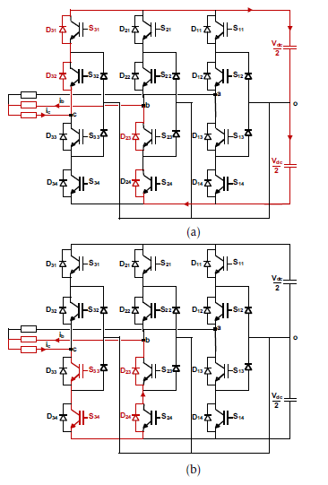 Figure 4: The current flowing during sector I in the case of a torque decrease under Legend (a): the DTC1 scheme, (b): the proposed DTC-2 scheme.
Let’s consider sector I, the vector selection table design of this scheme is synthesized as follows:
• To increase the torque, the DTC-2 scheme con-siders the same vectors applied in DTC-1,
• the vector V2 achieves the torque decrease. As illustrated in Figure. 4(b), the vector V2 is defined by a freewheeling phase involving the two
IGBTs S33 and S34 and the diodes D23 and D24. Compared to DTC-2, the DTC-1 scheme considers the vector V8 which characterized by a regenerative phase. During this phase, the currents ic and ib are forced to flow through the supply source Vdc and the diodes (D23, D24, D31 and D32) as shown in Figure. 4(a) . The currents slope observed under this phase has an absolute value higher than the one obtained under the freewheeling phase.
Consequently, the resulting DTC-2 strategy vector selection table is given in Table.4.
Table 4: The DTC-2 strategy vector selection table.
cτ +1 −1
Sector I V8(000011000011) V2(000000000011)
Sector II V9(001111000000) V3(000011000000)
Sector III V10(001100000011) V4(001100000000)
Sector IV V11(000000111100) V5(000000001100)
Sector V V12(110000110000) V6(000000110000)
Sector VI V7(110000000011) V1(110000000000)
3.3 DTC-3 strategy
it has been found that DTC-2 scheme is penalized by the commutation torque ripple. As illustrated in Figure.5(a), the difference between the slopes of the incoming and outgoing phases currents generates commutation torque dips. In view of that, there is a necessity to make equal the rising time and the falling one of the phase currents as illustrated in Figure.5(b).
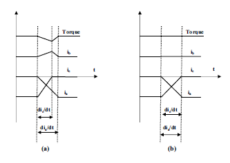 Figure 5: The behavior of the torque during commutation Legend (a): unequal slopes of the incoming and outgoing phases currents, (b): equal slopes of the incoming and outgoing phases currents.
The stator voltage equations of the BLDC motor are described by the equation (1). Neglecting the mutual inductance, va, vb and vc are given by the follow-
ing system :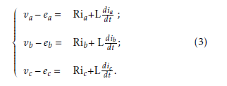
The Laplace Transform method can be used to solve this linear differential equations. Therefore the relation between the phase voltage and the phase current is dealt with using this method, and then the transfer function is similarly written as: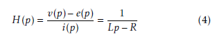
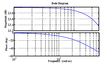 Figure 6: Approximated curve of the frequency response (bode-plot) of the BLDC motor.
Figure6 shows the approximated curve of the frequency response (bode-plot) based on equation (4). The plot displays the magnitude (in dB) and the phase (in degrees) of the system response as a function of frequency. Referring to this figure, the phase delay angle increases with the increase of the rotation speed. Moreover, this delay is more important at high speed. Consequently, the commutation torque dips is very serious at high speed.
To address the DTC-2 limitations, the third DTC scheme, noted DTC-3, is proposed . This strategy is based on the employ of a three-level torque controller. This controller generates 3 outputs as shown in Figure.7 :
• -1 corresponding to the torque decrease,
• +1 corresponding to the torque increase,
• +2 is activated when the torque drops duringcommutations from sector-to-sector .
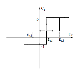 Figure 7: The three-level-torque controller character- istics.
Let’s consider sector I, the vector selection table design of this scheme is synthesized as follows:
• cτ=+1 and cτ=-1 are achieved by the same vectors used in DTC-2 scheme.
• The suppression of the commutation torquedips (cτ=+2) is achieved by the application of the vectors corresponding to the three-phase conduction mode. To equalize |dia/dt| and |dic/dt| ,at the beginning of sector II, in the case of a reference speed Ω∗ ≤ Ωlimit, the current ic is forced to flow through the IGBT S33, the clamped diode and the supply source V2dc instead of the uncontrollable diodes (D31 and D32) as shown in Figures. 8(b) and 8(c). For a reference speed Ω > Ωlimit, the current ic is forced to flow through the IGBTs (S33 , S34) and the supply source Vdc instead of the uncontrollable diodes (D31 and D32) as shown in Figures. 8(b) and 8(d).
Consequently,the resulting vector selection is given in Table.7.
4. Evaluation of the proposed DTC schemes effectiveness and performances
Simulation work has been accomplished to highlight the proposed strategies performances. Tables.5 and 6 gives the BLDC motor parameters and ratings.
Table 5: The ratings of BLDC motor
Current = 30A DC voltage = 24V
Rated torque = 2.5Nm PM flux-linkage = 14mWb
Power = 600W Rated speed = 2500rpm
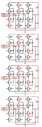 Figure 8: Current flowing during : Legend (a): sector I, (b): commutation under DTC-2 scheme, (c): commutation under DTC-3 scheme(Ω∗ ≤ Ωlimit) and (d): commutation under DTC-3 scheme (Ω∗ > Ωlimit).
 Figure 9: Simulated steady-state variables provided by the classic DTC-1 scheme at Ω = +100rad/s (subscript ”1”) and Ω = +150rad/s (subscript ”2”). Legend (a): sector succession, (b): stator currents, (c): control signal cτ and (d): electromagnetic torque.
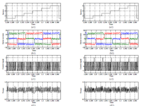 Figure 10: Simulated steady-state variables offered by the DTC-2(subscript ”1”) and the proposed DTC-3 (subscript ”2”) schemes at Ω = +100rad/s. Legend (a): sector succession, (b): stator currents, (c): control signal cτ and (d): electromagnetic torque.
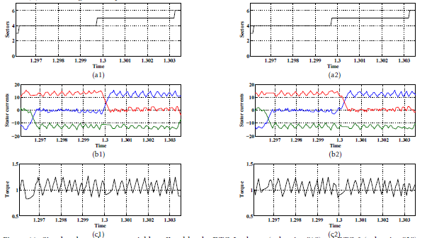 Figure 11: Simulated steady-state variables offered by the DTC-2 scheme (subscript ”1”)and DTC-3 (subscript ”2”) strategies for a speed Ω =+ 100rad/s. Legend (a): commutation from sector IV to sector V, (b): the stator currents zoom , and (c): the electromagnetic torque zoom.
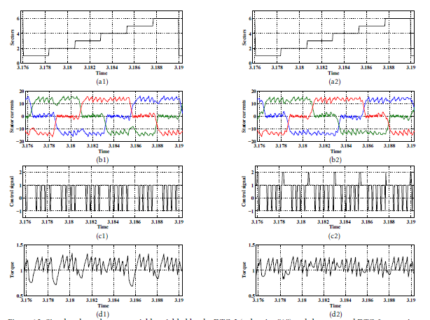 Figure 12: Simulated steady-state variables yielded by the DTC-2 (subscript ”1”) and the proposed DTC-3 strategies at Ω = +150rad/s. Legend (a): sector succession, (b): stator currents, (c): control signal cτ and (d): electromagnetic torque.
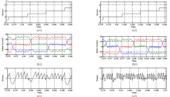 Figure 13: Simulated steady-state variables yielded by the DTC-2 strategy (subscript 1) and the proposed DTC-3 one for a speed Ω =+ 150rad/s . Legend (a): commutations from sector II to sector IV, (b): the stator currents zoom, and (c): the electromagnetic torque zoom .
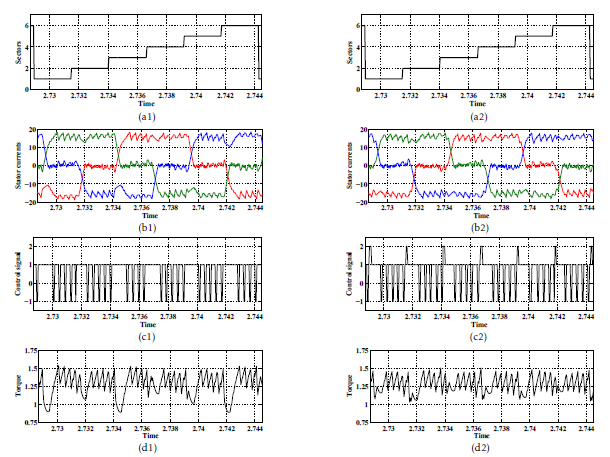 Figure 14: Simulated transient-state variables offered by the DTC-2(subscript ”1”) and the proposed DTC-3 schemes. Legend (a): sector succession, (b): stator currents, (c): control signal cτ and (d): electromagnetic torque.
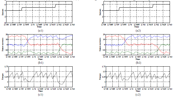 Figure 15: Simulated transient-state variables offered by the DTC-2 strategy (subscript 1) and the proposed DTC-3 one.Legend (a): commutations from sector V to sector VI, (b): the stator currents zoom , and (c): the electromagnetic torque zoom .
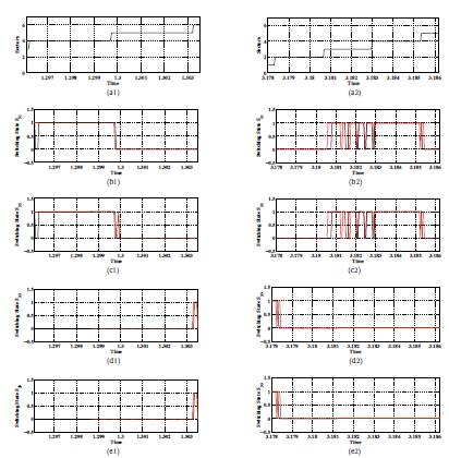 Figure 16: Simulated steady-state variables under the DTC-2 scheme (color black) and the proposed DTC-3 one (color red) for two reference speeds Ω =+ 100rad/s (subscript 1) and Ω =+ 150rad/s (subscript 2). Legend (a): commutations from sector II to sector IV, (b): S31, (c): S32, (d): S33, and (e): S34 .
Moreover, simulation conditions characterizing the simulation study are listed below:
• a sampling period Ts=55µs,
• a proportional gain Kp = 1,
• an integral gain Ki = 0.5,
• a load torque = 1Nm,
• a limit speed Ωlimit = 110rad/s
• the hysteresis bounds are: ετ1 = ±0.0012Nm and ετ2 = ±0.0036.
To analyze the effectiveness of the proposed DTC2 and DTC-3 strategies, this section deals with a simulation-based comparison between these strategies. By using MATLAB/SIMULINK, the proposed strategies are implemented. The obtained simulations results are illustrated in Figures. 10, 11, 12, 13, 14, 15.
4.1 Performance of the proposed strategies during sequence operation:
Figures.9, 10 and 12 show the waveforms of the current, the torque controller output cτ and the torque waveforms at steady-state operation.
By comparing Figures.9(d), 10(d) and 12(d), one clearly notice that the DTC-1 scheme leads to an important torque dips thanks to the application of the Intermediate active voltage vectors. Both DTC-3 and DTC-2 strategies lead to a low torque dips during sequence operation thanks to the application of the Half active voltage vectors.
During sequence operation, both DTC-2 and DTC3 schemes present almost the same torque waveforms. This is expected thanks to the application of the the same vectors. The difference concerns the torque decrease during commutations from sector to sector .
4.2 Performance of the proposed strategies during commutations from sector-to-sector :
To evaluate the proposed DTC schemes effectiveness during commutations from sector-to-sector , Figures. 11 and 13 give a zoom of the electromagnetic torque and the stator currents at steady-state operation. Figure.16 illustrates the steady-state waveforms of the switching states S31, S32, S33 and S34 with the sector succession.
As shown in Figures. 11(b1) and 13(b1), during the commutation from sector IV to sector V, the unbalancing between the current rising time and the current falling time affected the electromagnetic torque waveform. As a result of this, the DTC-2 strategy is penalized by a high torque dips. The comparison of Figures.10(c1) and 12(c1) confirms that commutation torque dips is more serious and more strong at high speed.
Compared to DTC-2, this commutation phenomenon is resolved for the DTC-3 strategy. Therefore, during the commutation from sector IV to sector V and in the case of the reference speed Ω∗ = 150rad/s (Ω∗ > Ωlimit), the current ic is forced to flow through the IGBTS (S31, S32 ) and the supply source Vdc instead of the freewheeling diodes (D33 and D34) as shown in Figures.16(b1), (b2), (b3) and (b4). However, from the analysis of Figures.16(a1), (a2), (a3) and (a4) in the case of a reference speed Ω∗ = 100rad/s (Ω∗ ≤ Ωlimit), it can be clearly noticed that the current ic is forced to flow through the IGBT S32, the clamped diode and the supply source V2dc instead of the freewheeling diodes (D33 and D34). Consequently, |dia/dt| and |dic/dt| are equal for both reference speeds which results a high dynamic of the torque without commutation ripple. These benefits are confirmed in Figures. 11(a2), 11(a3), 13(b2) and 13(b3).
The performance of DTC strategies under a transient-state is presented in Figures.14 and 15. Accordingly, compared to DTC-2 and DTC-1 schemes, one can evidently affirm that the developed DTC-3 scheme leads to the lower commutation torque dips for both transient and steady-state operations.
5. Conclusion
BLDC motor is integrated in various applications due to its different advantages. However, the BLDC motor drive has the drawback of high torque ripple which affects the performance of this system. Thus, torque ripple minimization is a crucial necessity. This paper has been focused on the development of two DTC schemes dedicated to BLDC motor drives. Simulation work has been accomplished to highlight the developed schemes effectiveness and performances. It has been found that the developed DTC-3 scheme has guaranteed the less distortion in the line currents and less commutation torque dips. This developed strategy has been based on the compensation of the difference between the slopes of the incoming and outgoing phases currents.
- J. Rodriguez, J.-S. Lai, and F. Z. ”Peng,Multilevel inverters: A survey of topologies controls and applications”, IEEE Trans. Ind. Electron., vol. 49, no. 4, pp. 724-738, Aug. 2002.
- Y. Liu, A. Q. Huang, W. Song, S. Bhattacharya, and G. Tan, ”Smallsignal model-based control strategy for balancing individual dc capacitor voltages in cascade multilevel inverterbased statcom, Industrial Electronics”,IEEE Transactions on, vol. 56, no. 6, pp. 22592269, 2009
- H. Vahedi,K. Al-Haddad, P.-A. Labbe, and S. Rahmani, ”Cascaded multilevel inverter with multicarrier pwm technique and voltage balancing feature”, in Industrial Electronics (ISIE), 2014 IEEE 23rd International Symposium on. IEEE, 2014, pp. 21552160
- J. P. Lyons, V. Vlatkovic, P. M. Espelange, A. A. M. Esser, and F. F. Want, ”Five level high power motor drive converter and control system”, U.S. Patent 6 058 031, May 2, 2000.
- S. Bernet, T. Bruckner, and P. Stiemer, Three-point converter and method for its operation, U.S. Patent 6 219 265, Apr. 17, 2001.
- M. A. Doss, E. Premkumar, G. R. Kumar, and J. Hussain, ”Harmonics and torque ripple reduction of Brushless DC Motor (BLDCM) using cascaded H-bridge multilevel inverter” , in Proc. IEEE ICPEC, Feb. 2013, pp. 296299.
- Chan, C. C., Jiang, J. Z., Xia, W., Chan, K. T. ”Novel wide range speed control of permanent magnet brushless motor drives”. IEEE transactions on power electronics, 10(5), 539- 546,1995
- T. Shi, Y. Guo, P. Song, and C. Xia, “A new approach of minimizing commutation torque ripple for brushless DC motor based on DC-DC converter”, IEEE Trans. Ind. Electron., vol. 57, no. 10, pp. 3483-3490, Oct. 2010.
- K. Ohishi, M. Nakao, K. Ohnishi, and K. Miyachi, “Microprocessor-controlled DC motor for load-insensitive position servo system”, IEEE Trans. Ind. Electron., vol. 34, no. 1, pp. 44-49, 1987.
- X. Huang, A. Goodman, C. Gerada, Y. Fang, and Q. Lu, “A single sided matrix converter drive for a brushless dc motor in aerospace applications”, IEEE Trans. Ind. Electron., vol. 59, no. 9, pp. 3542-3552, Sep. 2012.
- T. M. Jahns and W. I. Soong, “Pulsating torque minimization techniques for permanent magnet AC motor drives-a review”, IEEE Trans. Ind. Electron., vol. 43, no. 2, pp. 321-330, Apr. 1996.
- X. Li, C. Xia, Y. Cao, W. Chen, and T. Shi, “Commutation torque ripple reduction strategy of Z-source inverter fed brushless DC motor”, IEEE Trans. Power Electron., vol. 31, no. 11, pp. 7677-7690, Nov. 2016.
- C. Xia, Y. Xiao,W. Chen, and T. Shi, “Torque ripple reduction in brushless DC drives based on reference current optimization using integral variable structure control”, IEEE Trans. Ind. Electron., vol. 61, no. 2, pp. 738-752, Feb. 2014.
- G. Buja, M. Bertoluzzo, and R. K. Keshri, “Torque ripple-free operation of PM BLDC drives with petal-wave current supply”, IEEE Trans. Ind. Electron., vol. 62, no. 7, pp. 4034-4043, Jul. 2015.
- J. Fang, H. Li, and B. Han. “Torque ripple reduction in BLDC torque motor with non-ideal back EMF”, IEEE Trans. Power Electron., vol. 27, no. 11, pp. 4630-4637, Nov. 2012.
- W. Jiang, Y. Liao, J. Wang, P. Wang, and Y. Xie, “Improved control of BLDCM considering commutation torque ripple and commutation time in full speed range”, IEEE Trans. Power Electron., vol. 33, no. 5,pp. 4249-4260, June 2018.
- I. Takahashi and T. Noguchi, “A new quick-response and high efficiency control strategy of an induction motor”, IEEE Trans. Ind. Appl., vol. 22, no. 5, pp. 820-827, 1986.