
Enhancing the Energy/Power Efficiency of a DC Distribution Grid for Residential Buildings via Modular Architecture of DC/DC Solid State Transformers
Volume 3, Issue 5, Page No 288-297, 2018
Author’s Name: Faizan Dastgeer1,a), Hassan Erteza Gelani1, Faisal Ali1, Zahir Javed Paracha2
View Affiliations
1University of Engineering and Technology, Lahore, Department of Electrical Engineering, FSD Campus, Pakistan
2The University of Faisalabad – Amin Campus, Faisalabad, Pakistan
a)Author to whom correspondence should be addressed. E-mail: faizandastgeer@uet.edu.pk
Adv. Sci. Technol. Eng. Syst. J. 3(5), 288-297 (2018); ![]() DOI: 10.25046/aj030534
DOI: 10.25046/aj030534
Keywords: Energy Efficiency, Micro-grids, Modular Construction, Power Conversion, Power Distribution

Export Citations
DC power is apparently attempting to breach into the power system – the system which it once lost to the AC power paradigm. DC is already present in the generation, transmission and utilization sides of the system, leaving distribution as the only area where it has not shown any significant presence – this may be regarded as still in research phase. The current work aims to investigate efficiency enhancement of a DC power distribution system for residential buildings via the use of a modular approach for the DC/DC solid state transformers (SSTs). Specifically, DC distribution system shows reduced efficiency at light loads because of the lowering in efficiency of its constituent SSTs. Via the use of modular approach, a single SST is composed of smaller modules which may be turned on or off individually, for the purpose of improving the converter efficiency. In this paper, we utilize two methods of load division upon SST converter modules. As the efficiency of an SST is increased, the overall efficiency of the system increases because bulk power passes through these transformers.
Received: 06 September 2018, Accepted: 04 October 2018, Published Online: 12 October 2018
1. Introduction
Electrical energy, apparently being the most easily transferable (from one place to another) and convertible form of energy is, therefore, the most common source of energy for powering our residential and commercial buildings. Fundamentally, this energy has two forms available – AC and DC; and out of these, AC has been the dominant scenario for the power grid for the many past decades. This is in spite of the fact that the earliest power system was DC in nature. However, with the advent of electronics, DC is appearing again. It is present in the form of personal computers, laptops, and various other electronic gadgets. Variable speed drive (VSD) based air-conditioners [1], [2] also require DC as an intermediate stage between supply and load. The modern trend of LED-based lighting[3], [4], for our home and office buildings requires DC power as well. DC is also present on the energy generation side in the form of Solar Photovoltaic (PV) cells and wind farms with AC/DC/AC conversion [5], [6] , and on the bulk power transfer side in the form of High Voltage DC (HVDC) power transmission [7]–[9] with practical solutions available via Siemens [10] and ABB [11]. One may say that DC is struggling again to obtain a share of the electrical energy system.
Residential (and commercial) power distribution is one segment of the power system where DC has not yet obtained any significantly extensive appearance. DC power distribution may currently be regarded as in the research phase; wherein a number of relevant publications may be found in literature, some of the publications in the recent past are[12]–[20]. One of the important parameters of the system is its efficiency. Mathematically, efficiency may be expressed as:
 where ηE and ηP are energy and power efficiencies of a system. For a system with constant energy demand, both the quantities will be the same. The efficiency factor has a history with DC. It was apparently the system efficiency that led to the first overcoming of DC by AC in the 1880s, and then again it was apparently the efficiency that led to the re-appearance of DC in
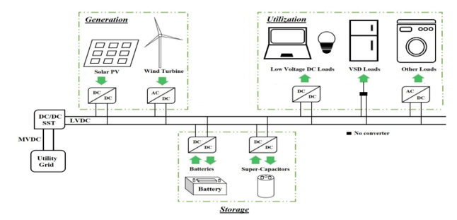 Figure 1: A DC microgrid schematic
the power system in the form of HVDC transmission. And now the efficiency of DC power distribution for a variety of cases is in the research phase. If DC can win the domain for power distribution, then an all DC power system may be envisioned. This may be especially true for the future micro-grids and a DC microgrid where DC generation can come from solar PV while the energy distribution and utilization are DC as well may become a reality. The concept of DC microgrids has seen a significant amount of research efforts. References [21]–[28] are some of the recent publications that mention DC microgrids.
The current effort is directed towards the efficiency of a DC distribution grid for residential buildings. DC/DC solid state transformers (SST) serve to replace the conventional transformers in such a system, and the efficiency of these power electronic transformers is crucial for the efficiency of the overall system. This research, which may be considered as an extension of our earlier efforts [16] and [17] aims to investigate the efficiency improvement of the system gained via the use of a modular architecture for the DC/DC SST. This architecture can allow the use of a required number of modules only in the converter and lower the converter losses leading to a higher value for the converter as well as system efficiency.
1.1. Contribution and Novelty of this work
The contribution of this effort is the enhancement of a residential DC grid efficiency at reduced system loading via a modular approach for system SSTs. DC distribution systems show a decrement in efficiency as the load reduces due to the efficiency variation of constituent DC/DC power electronic SSTs. Various studies related to the efficiency of DC systems are mentioned in the literature review subsection of this paper; none of the research efforts that we are aware of attempts to improve the residential DC distribution system efficiency via modular approach for the DC/DC SSTs. The next section discusses some of the applications of DC power distribution.
2. DC Distribution – Applications
2.1. Distributed Power Systems
Traditionally, DC has been present as a medium of power transfer for the case of distributed power systems (DPS) [29]–[33]. The power system of the international space station (ISS) is an example of this. The DC microgrid concept can be considered as a modified version of the DC DPS [34].
2.2. DC Microgrids
Microgrids may be described as a concept that can bring together distributed generation, residential/commercial utilization as well as hybrid storage technologies while having appropriate control to allow both utility-grid connected or independent operation. Figure 1 shows a schematic diagram of a DC microgrid. The extension of this concept to DC power may be considered as natural as:
- Distributed generation via solar and wind (having AC/DC/AC conversion) produce DC power.
- A wide variety of electronic loads in homes and offices require DC power.
- Storage technologies of batteries, super-capacitors and fuel cells [35], [36] are DC in nature.
The concept of DC microgrid has seen various research efforts as cited earlier, some of these will be discussed in the subsequent section.
2.3. Collector Parks for Renewable Energy
The concept of DC power collection has seen quite a number of research efforts for off-shore wind farms [37]–[42]. In these systems, power is collected from various off-shore wind turbines and then sent on-shore via DC lines. This way, the charging current and the corresponding losses that would have appeared if the line had been AC, can be avoided. The concept of DC power collection has been proposed for Solar Parks as well [43].
2.4. Miscellaneous
The concept of DC power distribution has been there for telecommunication facilities [44], [45] as well as data centers [46]–[49]. Reference [50] mentions a practical DC data center. Furthermore, with the advent of Hybrid Electric Vehicles, the need for their charging stations arises and DC bus based charging stations for the electric vehicles have been mentioned [51]–[54].
3. Literature Review / Background of the current effort
This section mentions various publications related to DC power distribution, especially its losses and efficiency. A background for the current work is also presented here. The subsequent subsection mentions the publications around/before 2012, while the subsection after it mentions the publications after 2012.
3.1. Past – Around/Before 2012
Reference [55] was an earlier effort of one of the current authors. DC power distribution paradigm was compared with a counterpart AC system with respect to system efficiency. Both Medium voltage (MV) and Low voltage (LV) portions were considered in the study. DC was found to be more efficient than AC; furthermore, a mathematical portion was presented to determine the minimum required efficiency for power electronic converters (PEC) in a DC system. However, this work did not discuss any method to increase the efficiency of PEC so as to meet the minimum requirement. The efficiency enhancement of the system via an increase of efficiency of constituent DC/DC power electronic SST is the topic of the current work.
- Hammerstrom compares DC and AC distributions for residential buildings in [56]. The results of this work are based on a number of stages of energy conversion – conduction losses are not included. The results showed that for the case of DC power being supplied via a rectifier, DC does not have an advantage over AC. However, if a local DC generator is present, higher efficiency will be obtained for DC.
Reference [57] presents the feasibility of DC for commercial facilities – power losses (conduction losses; PEC losses have not been mentioned explicitly) have been presented for AC and DC distribution systems. The authors mention that it may be concluded that DC can lead to big advantages. Reference [58] mentions that 380V DC brings reliability and efficiency to sustainable data centers. It further mentions that for data centers 380V DC is 28% more efficient than 208V AC and 7% more efficient than 415V AC. Reference [59] was an efficiency comparison of AC and DC power distribution for data centers. A small-scale demonstration showed 7% saving in input power for a 400V DC distribution as compared to 480V AC system.
The authors of [60] present a proto-type DC distribution system for residential applications where a hybrid energy source is present. A photovoltaic – wind – fuel cell hybrid energy system was developed and natively DC loads were used. Voltage and current results for the system were presented and a life-cycle cost was also given. However, the work did not include an efficiency study of the system. Amin et. al give energy consumption and losses for some common household appliances for LVAC and LVDC systems in [61]. They mention that total energy consumption is lowest for their 48V DC system.
Stark et. al present a loss comparison for AC and DC distribution in [62]. Both MVDC and LVDC portions have been included. The authors conclude that AC and DC distribution have the same merit if loads are half AC and half DC. The authors mention that the DC-DC converter is the defining device in the possible application of DC distribution. They also mention that one problem with these converters is a reduction of efficiency when operated below rating. This is precisely the issue which the current research effort may be able to address; via the use of modular approach for the main DC-DC power electronic SST, the SST, as well as the system efficiency, may be kept from lowering too much when the system load is reduced.
3.2. Present – Post-2012
The authors of [63] determine the savings in energy via the use of DC distribution for U.S. net-metered residential buildings. They present comparative results of energy savings for AC and DC building power distribution systems. They assume that distribution losses for both cases are comparable and all appliances are assumed to be DC-internal. They conclude that direct-DC could give significant energy savings in the U.S. houses with net-metered photovoltaic systems. This work was detailed enough to include not only the PEC losses occurring in the system but also the variation in PEC efficiency by variation of load. At partial loading, the PEC efficiency reduces. As mentioned earlier, the current effort is an attempt to avoid the lowering of SST PEC as well as system efficiency due to the reduction in system load.
The authors of [64] give comparative results of system efficiency for DC and AC power. Their analysis for office building indicates an efficiency gain of 14.9% when supplied by DC power as compared to AC power. The authors of [65] give an efficiency comparison of AC and DC power distribution for a commercial building. They conclude that for applications with AC and DC power sources with self-consumption and frequent battery usage, DC distribution may improve the system efficiency as compared to AC but the improvement is only 1.3%.
Fregosi et. al discuss a DC microgrid in [66]. They mention that an equivalent AC system was installed next to the DC system for efficiency comparison and the latter was found to use photovoltaic energy 8% more effectively. The authors of [67] give an efficiency comparison of AC and DC microgrid for the residential load. They assume that the residential load comprises equal proportions of AC and DC loads. For their comparative study, the authors conclude that the overall efficiency of the AC system was higher than that of DC; however, the addition of PV generation led to a reduction in AC system efficiency and an increase in efficiency of DC system.
A comparative analysis of system efficiency for AC and DC residential power distribution paradigms [16] was an effort of two of the current authors; related to DC distribution efficiency. Comparative system efficiency results can be presented for a variety of parameters of the systems such as voltage levels etc.; in [16] the comparative results of system efficiency were presented for variation in PEC efficiency values. The first part of the work showed that AC had better merit than DC. In the second part, we included the concept of Variable Speed Drive (VSD) based air-conditioning leading to a large increase in DC power demand of residential loads. DC distribution showed a slightly higher performance than AC for this case. A schematic diagram of the DC distribution with VSD loads is shown here in Figure 2.
The highest power loss in this DC system was found to be occurring in the primary DC/DC SST. The current research effort aims to reduce the losses occurring in this converter by using a modular approach based architecture for it.
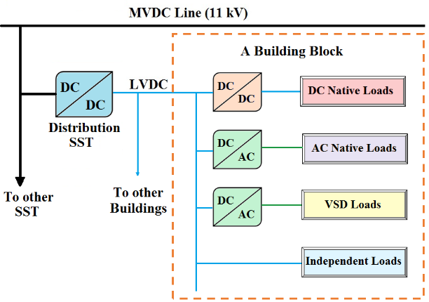 Figure 2: A portion of the DC distribution system [16]
Reference [15] gives a detailed efficiency comparison of DC and AC power distribution system. This work is aimed at commercial buildings with the concept of zero net energy (ZNE) in mind; where solar energy generation, as well as battery storage, are present on-site. The loads are assumed to be natively DC. Results are presented for two scenarios: small office having 48V DC system and medium office having 380V DC system. In the conclusion section, the authors mention that their research has found that the baseline efficiency savings are 9.9% and 11.9% for small and medium office buildings respectively; while the best-case scenario gives savings of 17.9% and 18.5%. They further mention that their study confirms that DC distribution is best suited for (commercial) buildings having the large solar capacity and large battery as well as a high voltage distribution backbone. The presence of battery is apparently a crucial factor for this research. The authors mention at one place that one of their results shows that a battery-less ZNE building barely benefits from DC distribution.
Reference [17] was another of earlier effort of two current authors related to DC distribution efficiency analysis. We performed the analysis for U.S. residential loads while taking into account load variation and the corresponding converter efficiency variation for the DC/DC converter transformer. A complete day was divided into three portions: Night (00:00 – 06:00), Day-1 (06:00 – 15:00) and Day-2 (15:00 – 00:00) and residential load was divided into these portions with Night, Day-1 and Day-2 demanding lowest to highest power respectively. An efficiency curve was chosen for the DC/DC converter transformer and its efficiency values were 86%, 89% and 90% for Night, Day-1 and Day-2; correspondingly, the system efficiency values were 82.85%, 85.64% and 85.73% for the three modes respectively. We went on to perform an analysis for the division of losses occurring in the system. The results are presented here in Figure 3.
The results depicted an increase in the DC/DC transformer losses (as a percentage of total losses occurring in the corresponding time) with the reduction of system load. We mentioned in the future work that, “A future work may be to investigate the feasibility of a DC power distribution system which comprises a modular architecture based DC/DC converter transformer.” In the current effort, we move towards DC distribution system efficiency enhancement via modular arrangement for its DC/DC SST. Prior to our work, [13] and [68] present an efficiency improvement of DC networks. Reference [68] improves the efficiency via optimal operation of multiple distributed generators in the system, while [13] contributes via proposing an enhanced tool for optimizing the analytical design of DC network that focuses on energy savings and improving efficiency. Our original contribution is the enhancing system efficiency of a DC grid at reduced loading via the use of modular SSTs. This modular approach and the system modeling will be presented in the subsequent section of this paper.
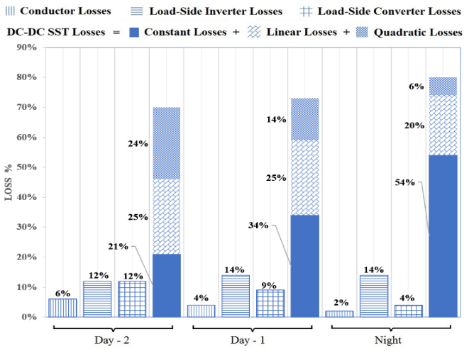 Figure 3: Loss distribution
4. Modeling of the DC Distribution Grid and Loads
4.1. Residential Load Modelling
The residential load modeling of a typical US building was presented by us in [16] using data from Energy Information Administration and Department of Energy; the model is discussed here briefly with Table 1 giving residential energy splits divided into A, D and I categories. These stand for AC native, DC native and Independent loads (such as Electric Iron which may be energized by AC or DC power provided suitable voltage level is supplied).
Based on data of Table 1 and taking space heating and cooling as DC power demanding loads, a single building the block may be built. As in [16], we assume 21 buildings to bunched together and connected to a single distribution DC/DC SST. However, in contrast to [16] which used 230V as the in-building distribution voltage for DC (as well as AC systems to get a fair comparison), here we choose 380V as the distribution voltage which may draw
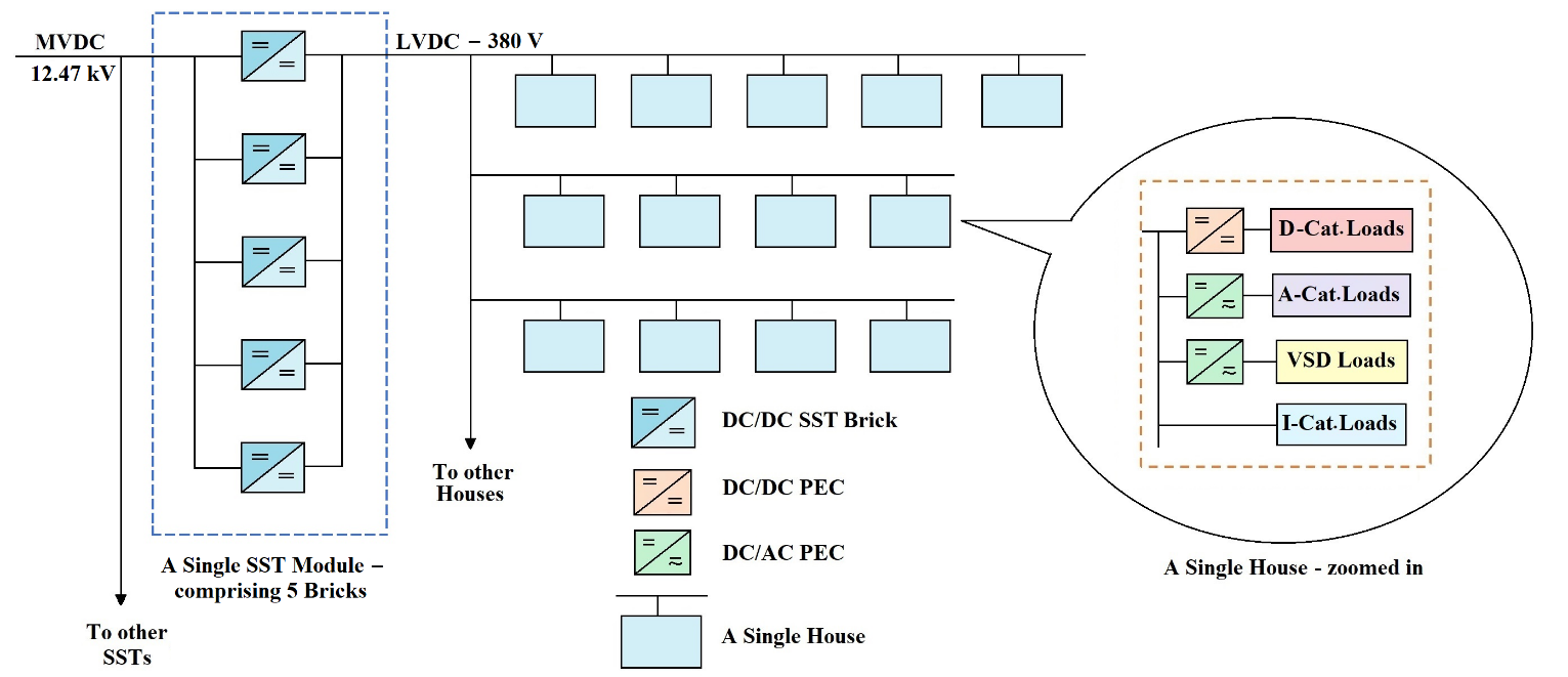 Figure 4: Schematic diagram of DC distribution grid with modular SST
its support from [15], [19]. Also, for the MVDC system, 12.47 kV (which is a standard US power distribution voltage) was used in the current effort. ‘Hare’ type ACSR conductor was assumed with an arbitrary spacing of 300m between two SSTs. The current system was assumed to comprise a total of 210 buildings which required ten SSTs (21 buildings/SST). For this system, total power demand at full load was 262.8 kW.
Table 1. Residential energy splits, categories & energy demand [16]
| Category |
Energy Used (Quad. Btu) |
Energy % |
A D I |
Energy kWh |
A cat. kWh |
D cat. kWh |
I cat. kWh |
| Space Heating | 0.42 | 8.78 | I | 2.64 | — | — | 2.64 |
| Water Heating | 0.48 | 9.93 | I | 2.98 | — | — | 2.98 |
| Space Cooling | 1.02 | 21.24 | A | 6.37 | 6.37 | — | — |
| Lighting | 0.53 | 11.04 | D | 3.31 | — | 3.31 | — |
| Refri-geration | 0.45 | 9.45 | A | 2.84 | 2.84 | — | — |
| Electronics | 0.33 | 6.86 | D | 2.06 | — | 2.06 | — |
| Wet Cleaning | 0.33 | 6.80 | A | 2.04 | 2.04 | — | — |
| Cooking | 0.11 | 2.36 | I | 0.71 | — | — | 0.71 |
| Computers | 0.19 | 3.95 | D | 1.19 | — | 1.19 | — |
| Other | 0.94 | 19.69 | 5.91 | 1.97 | 1.97 | 1.97 | |
| Total | 4.795 | 30.03 | 13.22 | 8.52 | 8.29 | ||
| Power demand in kW | 0.55 | 0.36 | 0.35 | ||||
4.2. Modular Architecture of DC/DC SST
Here the SST has been used with a modular architecture. Figure 4 shows a schematic diagram of a portion of the DC distribution system with modular architecture for the SST.
In [17] we used a single graph for modeling efficiency variation of a DC/DC PEC being used as SST. In this research, we have used five graphs from various sources to model SST efficiency variation. These graphs, presented in Figure 5, will be used one at a time. Two of these [69], [73] are from practical market available DC/DC converters while the remaining three are from research literature [70]–[72]. MATLAB/Simulink has been used for the simulations in this study where a single simulation experiment determines the total input power Pin_total demanded by the system. The system efficiency ηsys is then determined by
![]() where Po_total refers to the total power demand of the residential loads. For a single simulation experiment, a single graph out of the five reference curves given in Figure 5, is used to model the efficiency versus load variation characteristic of the modules called bricks of the SST.
where Po_total refers to the total power demand of the residential loads. For a single simulation experiment, a single graph out of the five reference curves given in Figure 5, is used to model the efficiency versus load variation characteristic of the modules called bricks of the SST.
5. Simulation runs and efficiency result
In contrast to [17] where we made everyday usage assumptions to include load variation and only three steps (Night, Day-1 and Day-2 as mentioned earlier) were used; over here we take ten steps of load variation – 10% to 100% of its value, as given in Table 2.
5.1. Basic Load Division Algorithm
To start with, the algorithm for load division upon bricks is kept simple. The idea is to keep one brick for taking up all the load variation while keeping all the others (if being used) at their maximum efficiency. Following are the steps for the basic algorithm.
- Load one brick only if total load is less than its Maximum efficiency point (MEP).
- If load exceeds this value, then keep one brick at its maximum efficiency point, and put all the remaining load on second brick
- If load exceeds MEP of the second brick, keep the second brick at its MEP and put all extra load on third brick and so on.
- If the MEP of all the converter bricks has been attained, beyond this, divide all the extra load equally among the bricks.
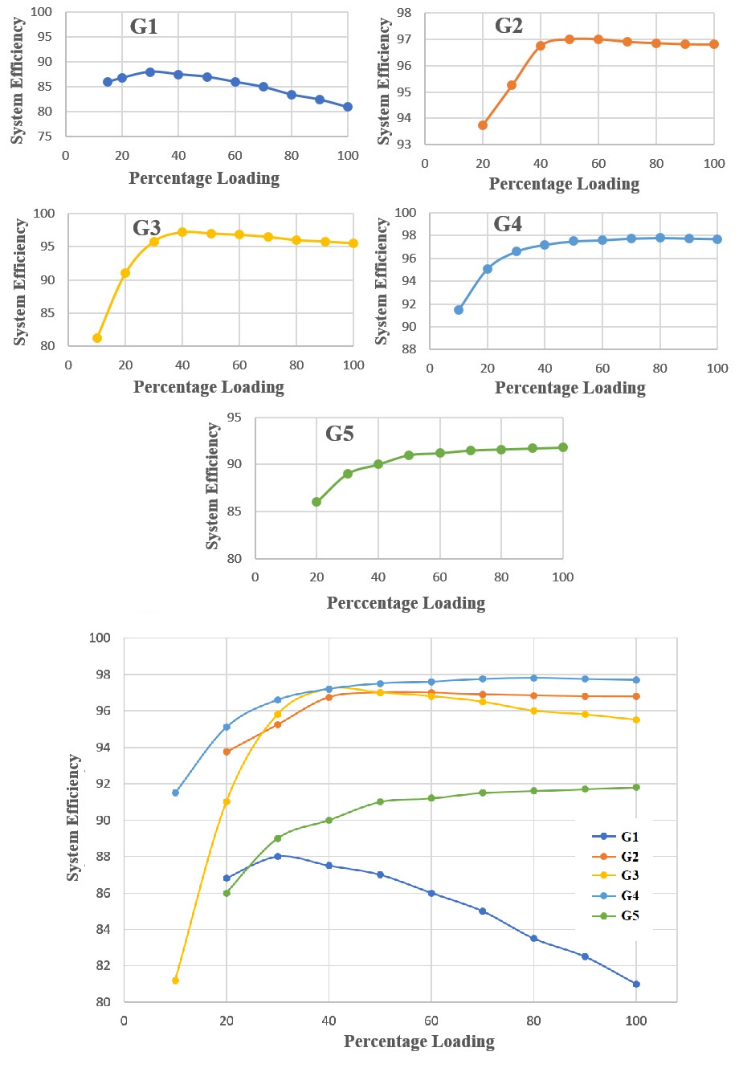 Figure 5:
1) G1- PowerStax F351 Full Brick 350W DC/DC PEC [69]
2) G2- Boost Mode Conversion efficiency curve – with V1 = 23V [70]
3) G3 – Conventional Dual Half-Bridge DC/DC converter [71]
4) G4 – CLLC DC/DC converter [72]
5) G5 – Cosel DBS700B28 – 700W DC/DC converter [73]
6) G1 – G5 combined
As an example, consider G1 graph. Its maximum efficiency point is at 29% loading, so for a single brick, this point occurs at 2.9 kW (since a single brick is rated at 10kW, while the five-brick modular SST is rated at 50kW). Now, as long as the SST load is less than 2.9kW, only one brick will operate. When the load exceeds 2.9kW, the first brick is fixed at its MEP load i.e. 2.9kW, and the next brick makes up for the remaining load. When the second brick load exceeds 2.9kW (i.e. total load exceeds 2 x 2.9kW), second brick is also fixed at the MEP of 2.9kW, and the remaining load (i.e. total load – 2.9kW – 2.9kW) is shifted on the third brick, and so on. Once all bricks are at maximum efficiency point (i.e. total load > 5 x 2.9kW), all bricks are loaded equally after this. The results of system simulation are presented in Tabular as well as graphical form in Table 2 and Figure 6. For comparison, the results of system efficiency with a non-modular SST have also been presented.
As evident from Table 2 and Figure 6, the modular SST based system shows a huge efficiency gain at a very low loading of the system. However, the single SST based system shows higher performance beyond 30% loading up to 60% load, and this may be attributed to the crude load division algorithm at this stage. After 60% loading, both systems show the same performance.
Table 2. Results of system efficiency – G1 – basic load division algorithm – modular and non-modular SST
|
Load % |
Load Po_total (kW)
|
Modular SST | Non-Modular SST | ||
|
Input Power Pin_total (kW)
|
System Efficiency % |
Input Power Pin_total (kW)
|
System Efficiency % |
||
| 10 | 26.28 | 32.58 | 80.7 | 33.81 | 77.7 |
| 20 | 52.55 | 66.72 | 78.8 | 67.02 | 78.4 |
| 30 | 78.83 | 99.36 | 79.3 | 99.67 | 79.1 |
| 40 | 105.1 | 132.04 | 79.6 | 131.71 | 79.8 |
| 50 | 131.38 | 164.75 | 79.75 | 163.32 | 80.4 |
| 60 | 157.66 | 197.06 | 80 | 197.06 | 80 |
| 70 | 183.94 | 230.72 | 79.7 | 230.72 | 79.7 |
| 80 | 210.21 | 264.4 | 79.5 | 264.4 | 79.5 |
| 90 | 236.49 | 298.74 | 79.2 | 298.74 | 79.2 |
| 100 | 262.8 | 335.52 | 78.3 | 335.52 | 78.3 |
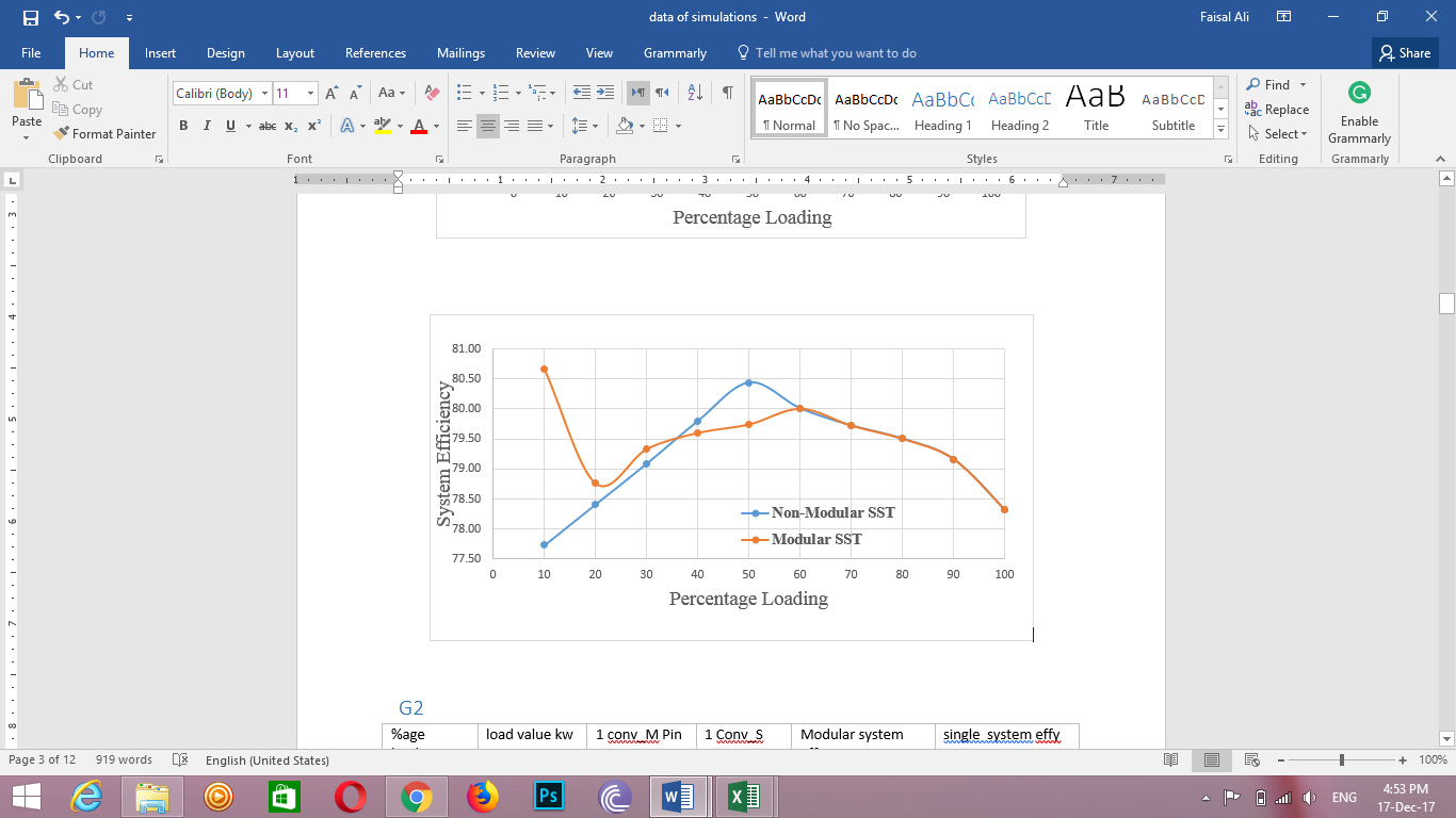 Figure 6: System efficiency comparison for modular & non-modular SST cases – for G1 reference graph
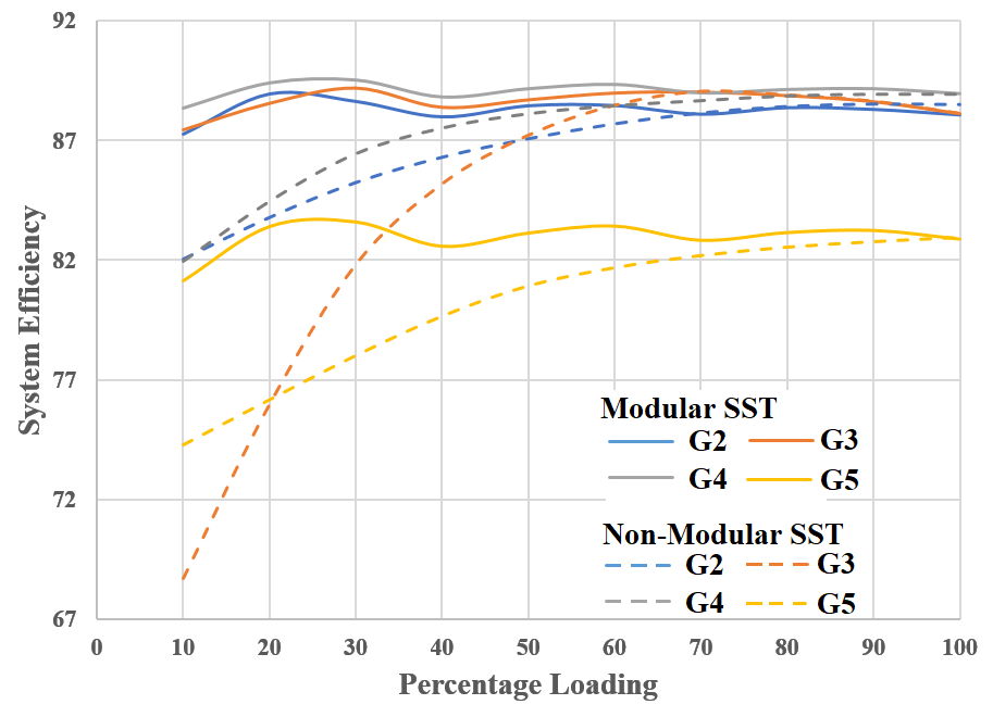 Figure 7: System efficiency comparison for modular & non-modular sst cases – for G2 – G5 reference graphs
Figure 7 shows the system performance comparisons for modular and non-modular SSTs based upon each of G2 – G5 reference curves. On the whole, the system shows superior performance with a modular SST. One reason for the improvement in system efficiency may be the reduction in the constant losses of the SST when it is used in the modular architecture. Assume that x% power of the SST rating is being wasted in the constant losses for the non-modular SST case. But when the SST is shifted to modular architecture; say only one brick is working at that time – then the percentage constant losses are reduced to x/5 (assuming same PEC efficiency characteristics and for a five brick SST). Hence at reduced load, the operation of only a limited number of bricks saves on losses and enhances overall SST and system efficiency. However, as the load increases, more and more bricks are turned on and eventually with all bricks on, the modular SST gives the same constant losses as a non-modular SST. In the next subsection, we present an improved load division technique to further enhance the system performance.
5.2. Modified Load Division Algorithm
The basic load division algorithm is modified to give better performance for system efficiency. The modified algorithm may be described as –
- Load one brick only if the total load is less than its MEP.
- If load exceeds this value, keep one brick at its MEP, and put remaining load in excess load bucket.
- If load exceeds MEP of the second brick, keep the second brick at its MEP and put an extra load in excess load bucket.
- If the MEP of all the converter bricks has been attained, beyond this, divide all the extra load equally between the bricks.
In this load division when the maximum number of bricks are at their MEP, the excess load bucket is handled in two ways
- The remaining load in excess load bucketis divided among all MEP bricks equally.
- If possible, the remaining load in excess load bucket is loaded on next brick which was not in use previously.
When these two ways of handling the excess load bucket are simulated for the system in parallel. Their resultant modular efficiency of the converters are compared and the one which is maximum is chosen. As an example, consider G1 graph again with MEP of 2.9 kW. As long as the SST load is less than 2.9kW, only one brick will operate. When the load exceeds 2.9kW, the first brick is fixed at its MEP load i.e. 2.9kW, and either the next brick makes up for the remaining load or remaining load is loaded on the first brick which was at MEP. The more efficient way of the two is selected. When the second brick load exceeds 2.9kW (i.e. total load exceeds 2 x 2.9kW), second brick is also fixed at the MEP of 2.9kW, and the remaining load (i.e. total load – 2.9kW – 2.9kW) is either shifted on the third brick or divided equally between MEP bricks and efficient way is selected with if condition in the algorithm. Using the same method other bricks are loaded Once all bricks are at maximum efficiency point (i.e. total load > 5 x 2.9kW), all bricks are loaded equally after this.
The results of system simulation for G1 are presented in Tabular as well as graphical form in Table 3 and Figure 8. Furthermore, the bulk of results for G2 – G5 are presented as before in a combined graph form in Figure 9. The non-modular SST based system efficiency results in Figure 9 are the same as those in Figure 7 and have been presented for the purpose of comparison.
Table 3. Results of system efficiency – G1 – modified load division algorithm – modular and non-mo dular SST
|
Load % |
Load Po_total (kW)
|
Modular SST | Non–Modular SST | ||
|
Input Power Pin_total (kW)
|
System Efficiency % |
Input Power Pin_total (kW)
|
System Efficiency % |
||
| 10 | 26.28 | 32.58 | 80.7 | 33.81 | 77.7 |
| 20 | 52.55 | 65.2 | 80.6 | 67.02 | 78.4 |
| 30 | 78.83 | 97.87 | 80.55 | 99.67 | 79.1 |
| 40 | 105.1 | 130.59 | 80.5 | 131.71 | 79.8 |
| 50 | 131.38 | 163.3 | 80.4 | 163.32 | 80.4 |
| 60 | 157.66 | 197.06 | 80 | 197.06 | 80 |
| 70 | 183.94 | 230.72 | 79.7 | 230.72 | 79.7 |
| 80 | 210.21 | 264.4 | 79.5 | 264.4 | 79.5 |
| 90 | 236.49 | 298.74 | 79.2 | 298.74 | 79.2 |
| 100 | 262.8 | 335.52 | 78.3 | 335.52 | 78.3 |
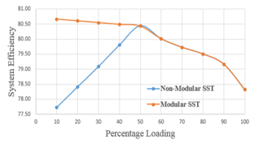 Figure 8: System efficiency comparison for modular & non-modular SST cases – for G1 reference graph
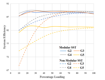 Figure 9: System efficiency comparison for modular & non-modular SST cases – for G2 – G5 reference graphs.
As can be observed by the mutual comparison of Figure 8 and Figure 6, the advanced load division technique keeps the Modular SST based system efficiency higher than the non-modular case for a longer range of system loading. Furthermore, Table 4 presents the comparative results of system efficiency when used with modular SST with basic and advanced load division methods for G2-G5. Although the advantage is slight, still the advanced technique gives better results at times. In any case, the modular SST based system proves to show higher system efficiency as compared to the non-modular SST based system.
It may be deemed that it is difficult to compare the results of system efficiency using five efficiency curves for the DC/DC SST among which two are market available converters while other three come from the research literature. Although published, the research literature used may have been using different criteria for their work. However, the aim of this paper is to present the idea of efficiency enhancement via modular architecture for the SSTs. Mutual comparison of the results is not the main concern – hence the use of disparate efficiency characteristics for the DC/DC SST should not be a problem
6. Future Work
This work may be extended to a detailed optimization technique for load division upon individual bricks of the modular SST with a goal to achieve the maximum overall system efficiency. Here we briefly discuss one such concept based upon Lagrange Multiplier.
The goal is to find such a load division of individual converter bricks which will lead to the lowest input power for the modular converter while supplying the desired load power. For this optimization, it may be more suitable to use a Pin versus Po graph rather than a Po vs efficiency graph. Such a graph for the G1 reference curve (presented in Figure 5) is presented here in Figure 10.
Assume that the general expression for this graph may be given as a quadratic equation as
![]() where α, β and γ may be derived via curve fitting for the graph, Po is the output power of a single brick and Pin is its input power. Then for the modular SST comprising ‘n’ bricks, it may be written that
where α, β and γ may be derived via curve fitting for the graph, Po is the output power of a single brick and Pin is its input power. Then for the modular SST comprising ‘n’ bricks, it may be written that
![]()
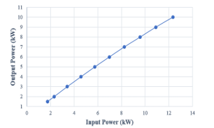 Figure 10: Input power versus output power graph – for G1 reference gap
The Pin-total becomes the objective function whose minimum value needs to be determined. Also, if PD is the total demand power at any given time from the modular SST, it can be written that
![]() Now, by augmenting the objective function with the constraint, a Lagrange multiplier may be formed as
Now, by augmenting the objective function with the constraint, a Lagrange multiplier may be formed as
![]() Such an analysis may be probed in order to derive the optimum value for Poi which will give the least Pin-total while supplying the required PD, hence giving the highest value for
Such an analysis may be probed in order to derive the optimum value for Poi which will give the least Pin-total while supplying the required PD, hence giving the highest value for
![]() where ηSST is the net efficiency of the modular SST.
where ηSST is the net efficiency of the modular SST.
Besides this, the areas of efficiency analysis and efficiency enhancement of DC distribution systems may be applied to a DC grid composed of the modern Zero Net Energy (ZNE) buildings whereby the DC/DC SSTs will be bi-directional allowing forward as well as the reverse flow of power. ZNE is a new trend for the modern home and DC distribution may facilitate the implementation of this concept.
Table 4. Power demands of A, D & I categories during three-day portions
| % Load |
Non-Modular SST System Efficiency |
Modular SST – Advanced Division System Efficiency |
Modular SST – Basic Division System Efficiency |
|||||||||
| G2 | G3 | G4 | G5 | G2 | G3 | G4 | G5 | G2 | G3 | G4 | G5 | |
| 10 | 82.06% | 68.7% | 81.93% | 74.26% | 87.28% | 87.43% | 88.35% | 81.14% | 87.28% | 87.43% | 88.35% | 81.14% |
| 20 | 83.79% | 75.97% | 84.45% | 76.15% | 88.95% | 88.56% | 89.39% | 83.39% | 88.95% | 88.56% | 89.39% | 83.39% |
| 30 | 85.24% | 81.81% | 86.45% | 78% | 88.64% | 89.24% | 89.51% | 83.58% | 88.64% | 89.21% | 89.51% | 83.58% |
| 40 | 86.29% | 85.18% | 87.53% | 79.65% | 88.83% | 89.03% | 89.21% | 83% | 88% | 88.39% | 88.81% | 82.57% |
| 50 | 87.06% | 87.21% | 88.13% | 80.92% | 88.59% | 89% | 89.36% | 83.42% | 88.46% | 88.71% | 89.15% | 83.12% |
| 60 | 87.68% | 88.46% | 88.47% | 81.68% | 88.71% | 89.07% | 89.34% | 83.41% | 88.47% | 89% | 89.33% | 83.41% |
| 70 | 88.13% | 89.04% | 88.68% | 82.19% | 88.55% | 89.04% | 89.19% | 83.26% | 88.11% | 89.04% | 88.98% | 82.82% |
| 80 | 88.4% | 88.89% | 88.88% | 82.54% | 88.6% | 88.89% | 89.23% | 83.29% | 88.38% | 88.89% | 89.12% | 83.14% |
| 90 | 88.5% | 88.63% | 88.95% | 82.77% | 88.5% | 88.63% | 89.17% | 83.25% | 88.31% | 88.63% | 89.15% | 83.23% |
| 100 | 88.48% | 88.12% | 88.95% | 82.95% | 88.48% | 88.12% | 89.09% | 83.19% | 88.08% | 88.12% | 88.95% | 82.87% |
7. Conclusion
The use of modular architecture can help against the lowering of power/energy efficiency of a power electronic DC/DC SST. Hence the overall system efficiency of a DC grid may be improved via modular SST approach. In the current paper, we have demonstrated this via DC grid simulations for five different efficiency characteristics of the DC/DC SST, two of the graphs were derived from practical market available DC/DC converters while the other three came from research publications. We have two techniques for load division among SST bricks and although, there was not a much significant difference in system performance between the proposed basic and advanced load division methods; nevertheless, the results gave a good performance against a non-modular SST based system. An in-depth optimization of the load division technique may be a future direction for this work.
DC power distribution, given up a long time ago, is now witnessing a revival and the time may come when we are living in DC-based homes, or at least the modern homes with advanced integration of renewable-energy/ZNE concept have shifted to DC power. To this end, however, a lot of research and development may be required which may include a variety of areas, one of which is the efficiency of the system. And the factor of efficiency may be deemed do-or-die for the system, after all, it was this factor that once led to the ousting of DC in the early days of the power system. Again, this factor is important for the re-introduction of DC power in the system in the form of HVDC transmission lines. The ongoing push for higher efficiencies may even be seen in our homes via the acceptance of LEDs for lighting and inverter based (VSD based) air-conditioning technologies.
8.Funding
This research did not receive any specific grant from funding agencies in the public, commercial, or not-for-profit sectors.
- M. B. Yurtseven, E. Erkin, E. Acuner, S. Mete, and S. Onaygil, “An experimental investigation of energy saving potentials for room type variable-speed air conditioners in public offices: A case study from Istanbul,” Energy Build., vol. 68, pp. 165–171, 2014.
- B. K. Bose, “Power Electronics and Motor Drives Recent Progress and Perspective,” IEEE Trans. Ind. Electron., vol. 56, no. 2, pp. 581–588, Feb. 2009.
- F. G. Montoya, A. Pena-Garcia, A. Juaidi, and F. Manzano-Agugliaro, “Indoor lighting techniques: An overview of evolution and new trends for energy saving,” Energy Build., vol. 140, pp. 50–60, 2017.
- B.-L. Ahn, C.-Y. Jang, S.-B. Leigh, S. Yoo, and H. Jeong, “Effect of LED lighting on the cooling and heating loads in office buildings,” Appl. Energy, vol. 113, pp. 1484–1489, 2014.
- Z. Chen, J. M. Guerrero, and F. Blaabjerg, “A Review of the State of the Art of Power Electronics for Wind Turbines,” IEEE Trans. Power Electron., vol. 24, no. 8, pp. 1859–1875, Aug. 2009.
- F. Blaabjerg, M. Liserre, and K. Ma, “Power Electronics Converters for Wind Turbine Systems,” IEEE Trans. Ind. Appl., vol. 48, no. 2, pp. 708–719, Mar. 2012.
- L. Zhao, J. Lu, X. Cui, L. Xie, Y. Ju, and K. He, “The Altitude Effect and Correction of Audible Noise for HVDC Transmission Lines,” IEEE Trans. Power Deliv., vol. 32, no. 4, pp. 1954–1963, Aug. 2017.
- J. M. Johnson and A. Yadav, “Complete protection scheme for fault detection, classification and location estimation in HVDC transmission lines using support vector machines,” IET Sci. Meas. Technol., vol. 11, no. 3, pp. 279–287, 2017.
- A. Kalair, N. Abas, and N. Khan, “Comparative study of HVAC and HVDC transmission systems,” Renew. Sustain. Energy Rev., vol. 59, pp. 1653–1675, 2016.
- “HV Direct Current Transmission System (HVDC).” [Online]. Available: https://www.energy.siemens.com/hq/en/power-transmission/hvdc/. Last accessed date: 31 July, 2017
- “HVDC.” [Online]. Available: http://new.abb.com/systems/hvdc. Last accessed date: 31 July, 2017
- B. Glasgo, I. L. Azevedo, and C. Hendrickson, “How much electricity can we save by using direct current circuits in homes? Understanding the potential for electricity savings and assessing the feasibility of a transition towards DC powered buildings,” Appl. Energy, vol. 180, pp. 66–75, 2016.
- M. Fantauzzi, D. Lauria, F. Mottola, and A. Scalfati, “Sizing energy storage systems in DC networks: A general methodology based upon power losses minimization,” Appl. Energy, vol. 187, pp. 862–872, 2017.
- G.-H. Gwon, C.-H. Kim, Y.-S. Oh, C.-H. Noh, T.-H. Jung, and J. Han, “Mitigation of voltage unbalance by using static load transfer switch in bipolar low voltage DC distribution system,” Int. J. Electr. Power Energy Syst., vol. 90, pp. 158–167, 2017.
- D. L. Gerber, V. Vossos, W. Feng, C. Marnay, B. Nordman, and R. Brown, “A simulation-based efficiency comparison of AC and DC power distribution networks in commercial buildings,” Appl. Energy, p. , 2017.
- F. Dastgeer and H. E. Gelani, “A Comparative analysis of system efficiency for AC and DC residential power distribution paradigms,” Energy Build., vol. 138, pp. 648–654, 2017.
- H. E. Gelani and F. Dastgeer, “Efficiency Analyses of a DC Residential Power Distribution System for the Modern Home,” Adv. Electr. Comput. Eng., vol. 15, no. 1, pp. 135–142, 2015.
- T. Dragicevic, J. C. Vasquez, J. M. Guerrero, and D. Skrlec, “Advanced LVDC Electrical Power Architectures and Microgrids: A step toward a new generation of power distribution networks.,” IEEE Electrif. Mag., vol. 2, no. 1, pp. 54–65, Mar. 2014.
- M. H. Ryu, H. S. Kim, J. W. Baek, H. G. Kim, and J. H. Jung, “Effective Test Bed of 380-V DC Distribution System Using Isolated Power Converters,” IEEE Trans. Ind. Electron., vol. 62, no. 7, pp. 4525–4536, Jul. 2015.
- B. Nordman and K. Christensen, “DC Local Power Distribution: Technology, Deployment, and Pathways to Success,” IEEE Electrif. Mag., vol. 4, no. 2, pp. 29–36, Jun. 2016.
- A. A. Mohamed, A. T. Elsayed, T. A. Youssef, and O. A. Mohammed, “Hierarchical control for DC microgrid clusters with high penetration of distributed energy resources,” Electr. Power Syst. Res., vol. 148, pp. 210–219, 2017.
- Q. Xu et al., “A Decentralized Dynamic Power Sharing Strategy for Hybrid Energy Storage System in Autonomous DC Microgrid,” IEEE Trans. Ind. Electron., vol. 64, no. 7, pp. 5930–5941, Jul. 2017.
- N. Yang, B. Nahid-Mobarakeh, F. Gao, D. Paire, A. Miraoui, and W. Liu, “Modeling and stability analysis of multi-time scale DC microgrid,” Electr. Power Syst. Res., vol. 140, pp. 906–916, 2016.
- C. N. Papadimitriou, E. I. Zountouridou, and N. D. Hatziargyriou, “Review of hierarchical control in DC microgrids,” Electr. Power Syst. Res., vol. 122, pp. 159–167, 2015.
- Q. Yang, L. Jiang, H. Zhao, and H. Zeng, “Autonomous Voltage Regulation and Current Sharing in Islanded Multi-inverter DC Microgrid,” IEEE Trans. Smart Grid, vol. 3053, no. c, pp. 1–1, 2017.
- W. J. Ma, J. Wang, X. Lu, and V. Gupta, “Optimal Operation Mode Selection for a DC Microgrid,” IEEE Trans. Smart Grid, vol. 7, no. 6, pp. 2624–2632, Nov. 2016.
- C. Yin, H. Wu, F. Locment, and M. Sechilariu, “Energy management of {DC} microgrid based on photovoltaic combined with diesel generator and supercapacitor,” Energy Convers. Manag., vol. 132, pp. 14–27, 2017.
- M. I. Ghiasi, M. A. Golkar, and A. Hajizadeh, “Lyapunov Based-Distributed Fuzzy-Sliding Mode Control for Building Integrated-DC Microgrid With Plug-In Electric Vehicle,” IEEE Access, vol. 5, pp. 7746–7752, 2017.
- C. M. Wildrick, F. C. Lee, B. H. Cho, and B. Choi, “A method of defining the load impedance specification for a stable distributed power system,” in Power Electronics Specialists Conference, 1993. PESC ’93 Record., 24th Annual IEEE, 1993, pp. 826–832.
- J. Liu, X. Feng, F. C. Lee, and D. Borojevich, “Stability margin monitoring for DC distributed power systems via perturbation approaches,” IEEE Trans. Power Electron., vol. 18, no. 6, pp. 1254–1261, Nov. 2003.
- X. Feng, C. Liu, Z. Ye, F. C. Lee, and D. Borojevic, “Monitoring the stability of DC distributed power systems,” in Industrial Electronics Society, 1999. IECON ’99 Proceedings. The 25th Annual Conference of the IEEE, 1999, vol. 1, pp. 367–372 vol.1.
- X. Feng and F. C. Lee, “On-line measurement on stability margin of DC distributed power system,” in APEC 2000. Fifteenth Annual IEEE Applied Power Electronics Conference and Exposition (Cat. No.00CH37058), 2000, vol. 2, pp. 1190–1196 vol.2.
- X. Feng, K. Xing, F. C. Lee, and D. Borojevic, “Individual load impedance specification for a stable DC distributed power system,” APEC ’99. Fourteenth Annu. Appl. Power Electron. Conf. Expo. 1999 Conf. Proc. (Cat. No.99CH36285), vol. 2, pp. 923–929 vol.2, 1999.
- X. Wang et al., “Decentralized Impedance Specifications for Small-Signal Stability of DC Distributed Power Systems,” IEEE J. Emerg. Sel. Top. Power Electron., vol. PP, no. 99, p. 1, 2017.
- N. A. Ahmed, A. K. Al-Othman, and M. R. AlRashidi, “Development of an efficient utility interactive combined wind/photovoltaic/fuel cell power system with MPPT and DC bus voltage regulation,” Electr. Power Syst. Res., vol. 81, no. 5, pp. 1096–1106, 2011.
- C. N. Papadimitriou and N. A. Vovos, “Integration of a hybrid fuel cell-battery system to a distribution grid,” Electr. Power Syst. Res., vol. 81, no. 7, pp. 1299–1307, 2011.
- R. Barrera-Cardenas and M. Molinas, “Comparative Study of Wind Turbine Power Converters Based on Medium-Frequency AC-Link for Offshore DC-Grids,” IEEE J. Emerg. Sel. Top. Power Electron., vol. 3, no. 2, pp. 525–541, Jun. 2015.
- F. Deng and Z. Chen, “Operation and Control of a DC-Grid Offshore Wind Farm Under DC Transmission System Faults,” IEEE Trans. Power Deliv., vol. 28, no. 3, pp. 1356–1363, Jul. 2013.
- S. Chuangpishit, A. Tabesh, Z. Moradi-Shahrbabak, and M. Saeedifard, “Topology Design for Collector Systems of Offshore Wind Farms With Pure DC Power Systems,” IEEE Trans. Ind. Electron., vol. 61, no. 1, pp. 320–328, Jan. 2014.
- J. Robinson, D. Jovcic, and G. Joos, “Analysis and Design of an Offshore Wind Farm Using a MV DC Grid,” IEEE Trans. Power Deliv., vol. 25, no. 4, pp. 2164–2173, Oct. 2010.
- C. Meyer, M. Höing, A. Peterson, and R. W. De Doncker, “Control and design of DC grids for offshore wind farms,” IEEE Trans. Ind. Appl., vol. 43, no. 6, pp. 1475–1482, 2007.
- F. Deng and Z. Chen, “Design of protective inductors for HVDC transmission line within DC grid offshore wind farms,” IEEE Trans. Power Deliv., vol. 28, no. 1, pp. 75–83, 2013.
- H. A. B. Siddique and R. W. De Doncker, “Evaluation of DC Collector-Grid Configurations for Large Photovoltaic Parks,” IEEE Trans. Power Deliv., vol. PP, no. 99, p. 1, 2017.
- M. Schweizer-Berberich and H. Willmes, “Concept for a 48 V DC Power Supply System with Lithium Ion Batteries for Telecom Applications,” in INTELEC 05 – Twenty-Seventh International Telecommunications Conference, 2005, pp. 31–36.
- H. J. Chiu, T. F. Pan, C. J. Yao, and Y. K. Lo, “Automatic EMI Measurement and Filter Design System for Telecom Power Supplies,” IEEE Trans. Instrum. Meas., vol. 56, no. 6, pp. 2254–2261, Dec. 2007.
- E. Taylor, M. Korytowski, and G. Reed, “Voltage transient propagation in AC and DC datacenter distribution architectures,” in 2012 IEEE Energy Conversion Congress and Exposition (ECCE), 2012, pp. 1998–2004.
- K. Tan, X. Song, C. Peng, P. Liu, and A. Q. Huang, “Hierarchical protection architecture for 380V DC data center application,” in 2016 IEEE Energy Conversion Congress and Exposition (ECCE), 2016, pp. 1–8.
- B. R. Shrestha, T. M. Hansen, and R. Tonkoski, “Reliability analysis of 380V DC distribution in data centers,” in 2016 IEEE Power Energy Society Innovative Smart Grid Technologies Conference (ISGT), 2016, pp. 1–5.
- C. Wang and P. Jain, “A quantitative comparison and evaluation of 48V DC and 380V DC distribution systems for datacenters,” in 2014 IEEE 36th International Telecommunications Energy Conference (INTELEC), 2014, pp. 1–7.
- “World’s most powerful DC data center online.” [Online]. Available: http://www.abb.com/cawp/seitp202/187b2f29acaea090c1257a0e0029fb1a.aspx. Last accessed date: 31 July, 2017
- S. Rivera, B. Wu, S. Kouro, V. Yaramasu, and J. Wang, “Electric Vehicle Charging Station Using a Neutral Point Clamped Converter with Bipolar DC Bus,” IEEE Trans. Ind. Electron., vol. 62, no. 4, pp. 1999–2009, 2015.
- G. F. Reed, B. M. Grainger, A. R. Sparacino, R. J. Kerestes, and M. J. Korytowski, “Advancements in medium voltage DC architecture development with applications for powering electric vehicle charging stations,” Energytech, 2012 IEEE, pp. 1–8, 2012.
- C. Capasso and O. Veneri, “Experimental study of a DC charging station for full electric and plug in hybrid vehicles,” Appl. Energy, vol. 152, pp. 131–142, 2015.
- S. Jung, H. Lee, C. S. Song, J. H. Han, W. K. Han, and G. Jang, “Optimal Operation Plan of the Online Electric Vehicle System Through Establishment of a DC Distribution System,” IEEE Trans. Power Electron., vol. 28, no. 12, pp. 5878–5889, Dec. 2013.
- F. Dastgeer and A. Kalam, “Efficiency comparison of DC and AC distribution systems for distributed generation,” in 2009 Australasian Universities Power Engineering Conference, 2009, pp. 1–5.
- D. J. Hammerstrom, “AC Versus DC Distribution Systems – Did We Get it Right?,” in 2007 IEEE Power Engineering Society General Meeting, 2007, pp. 1–5.
- A. Sannino, G. Postiglione, and M. H. J. Bollen, “Feasibility of a DC network for commercial facilities,” IEEE Trans. Ind. Appl., vol. 39, no. 5, pp. 1499–1507, 2003.
- G. AlLee and W. Tschudi, “Edison Redux: 380 Vdc Brings Reliability and Efficiency to Sustainable Data Centers,” IEEE Power Energy Mag., vol. 10, no. 6, pp. 50–59, Nov. 2012.
- A. Pratt, P. Kumar, and T. V Aldridge, “Evaluation of 400V DC distribution in telco and data centers to improve energy efficiency,” in INTELEC 07 – 29th International Telecommunications Energy Conference, 2007, pp. 32–39.
- E. Cetin, A. Yilanci, H. K. Ozturk, M. Colak, I. Kasikci, and S. Iplikci, “A micro-DC power distribution system for a residential application energized by photovoltaic-wind/fuel cell hybrid energy systems,” Energy Build., vol. 42, no. 8, pp. 1344–1352, 2010.
- M. Amin, Y. Arafat, S. Lundberg, and S. Mangold, “Low voltage DC distribution system compared with 230 V AC,” 2011 IEEE Electr. Power Energy Conf. EPEC 2011, pp. 340–345, 2011.
- M. Starke, L. M. Tolbert, and B. Ozpineci, “AC vs. DC distribution: A loss comparison,” in 2008 IEEE/PES Transmission and Distribution Conference and Exposition, 2008, pp. 1–7.
- V. Vossos, K. Garbesi, and H. Shen, “Energy savings from direct-DC in U.S. residential buildings,” Energy Build., vol. 68, no. PARTA, pp. 223–231, 2014.
- Z. Liu and M. Li, “Research on Energy Efficiency of DC Distribution System,” AASRI Procedia, vol. 7, pp. 68–74, 2014.
- J. Brenguier, M. Vallet, and F. VAILLANT, “Efficiency gap between AC and DC electrical power distribution system,” in 2016 IEEE/IAS 52nd Industrial and Commercial Power Systems Technical Conference (I CPS), 2016, pp. 1–6.
- D. Fregosi et al., “A comparative study of DC and AC microgrids in commercial buildings across different climates and operating
profiles,” in 2015 IEEE First International Conference on DC Microgrids (ICDCM), 2015, pp. 159–164. - H. R. Atia, A. Shakya, P. Tandukar, U. Tamrakar, T. M. Hansen, and R. Tonkoski, “Efficiency analysis of AC coupled and DC coupled microgrids considering load profile variations,” IEEE Int. Conf. Electro Inf. Technol., vol. 2016–Augus, pp. 695–699, 2016.
- S. H. Lee and J.-W. Park, “Optimal operation of multiple DGs in DC distribution system to improve system efficiency,” in 2016 IEEE/IAS 52nd Industrial and Commercial Power Systems Technical Conference (I CPS), 2016, pp. 1–9.
- “Powerstax F351 – Full Brick 350W DC/DC converter.” [Online]. Available:http://www.powerstax.com/wpcontent/uploads/2017/06/F211_351_501.pdf. Last accessed date: 22 July, 2017.
- D. Sha, X. Wang, and D. Chen, “High Efficiency Current-Fed Dual Active Bridge DC-DC Converter with ZVS Achievement Throughout Full Range of Load Using Optimized Switching Patterns,” IEEE Trans. Power Electron., vol. PP, no. 99, p. 1, 2017.
- H. Fan and H. Li, “High-Frequency Transformer Isolated Bidirectional DC-DC Converter Modules With High Efficiency Over Wide Load Range for 20 kVA Solid-State Transformer,” IEEE Trans. Power Electron., vol. 26, no. 12, pp. 3599–3608, Dec. 2011.
- H. S. Kim, M. H. Ryu, J. W. Baek, and J. H. Jung, “High-Efficiency Isolated Bidirectional AC-DC Converter for a DC Distribution System,” IEEE Trans. Power Electron., vol. 28, no. 4, pp. 1642–1654, Apr. 2013.
- “Cosel DBS700B28 – 700W DC/DC converter.” [Online]. Available: https://en.cosel.co.jp/product/powersupply/DBS/DBS700B/DBS700B28/. Last accessed date: 22 July, 2017.