Development and Testing of Intelligent Wheelchair Controller for Quadriplegic Patients
 , Sebastian Neubert 2, Norbert Stoll 2, Kerstin Thurow 3
Adv. Sci. Technol. Eng. Syst. J. 3(5), 220–225 (2018);
 DOI: 10.25046/aj030527
In this research paper, the development and evaluating of a smart controller for electrical powered wheelchairs are presented. The controller aimed to assist quadriplegic, paralyzed, and handicap patients who cannot use their hands to drive an electrical wheelchair by using a joystick controller. Two sub control units have been combined in one hybrid system to create the current version which are voice, and head tilt controllers. They are activated and operated in parallel at the same time to allow the wheelchair user to choose the preferred control method. The voice controller is activated by the user’s voice command to control the wheelchair instead of a joystick. The head tilt controller uses the user’s head motions to create control commands instead of the joystick controller. The head tilt controller design is based on using two embedded MEMS orientation detection modules as input measurement units. The system uses a modern low power consumption microcontroller to analyze the received information and data from inputs and creating the prompt control commands and send it to the wheelchair motors driver as an output unit.
1. Introduction
The use of assistive and rehabilitation applications has increased rapidly in recent years because of the huge increase in the numbers of handicapped and paralyzed people. In the traditional wheelchair, joysticks controller has been used to generate the control commands, which requires good control of the user’s hand. However, quadriplegic and paralyzed patients cannot use a conventional joystick controller. Thus, several new technologies, methods, and inventions have to be developed to serve this class of patients and to reduce their sufferance. Nowadays, several input signals from the user’s body can be used such as body gesture and motions [1-3], brain electrical signals [4-6], user voice commands [7-9], and electrical activity in the body muscles (EMG) [10-11]. Several approaches have been used for each signal. Each approach has its advantages and disadvantages, more details and information are available in [12-13]
In this paper, the design, and evaluation of the hybrid controller for electrical wheelchairs are explained. The controller design takes into consideration the target users’ requirements. The target users lost the ability to use their upper and lower limbs and cannot handle a conventional joystick controller. The novelty of the proposed system is based on using more than one controller flexibly to allow the user choosing the preferred controller. The novel implementation of the voice controller allows the system to avoid false positive (FP) errors by using two different voice recognition modules combined by a false positive errors cancelation algorithm. The head tilt controller has a unique design to perform several tasks based on using many functions to improve the performance of the system in different situations such as applied emergency stop or driving the system in ramps and non-straight roads. The system has been tested with the implementation of several tasks, some important factors such as response time and stop distance have been measured to check the new system controller’s performance in comparison to an original joystick controller. The combination of several sensors and detection units in the voice and head tilt controllers produce a durable and simple to use system that helps the target users to enhance the quality of daily life. The proposed work is an improvement and a development of previous work that can be found in [14-15].
2. Methodology
There are three main layers of the system which are the input layer, the main processor, and the execution platforms. The system main layers have been explained in Fig. 1. The input layer includes all the sensors and modules that are responsible for picking up the control signals from the user side and sending it to the main processing unit. The main processor analyses and processes the data and information of the sensors and modules in the input layer. It is responsible for the generation and sending of the control commands to the output layer which is also called the execution platforms. The following section explains each layer in detail:
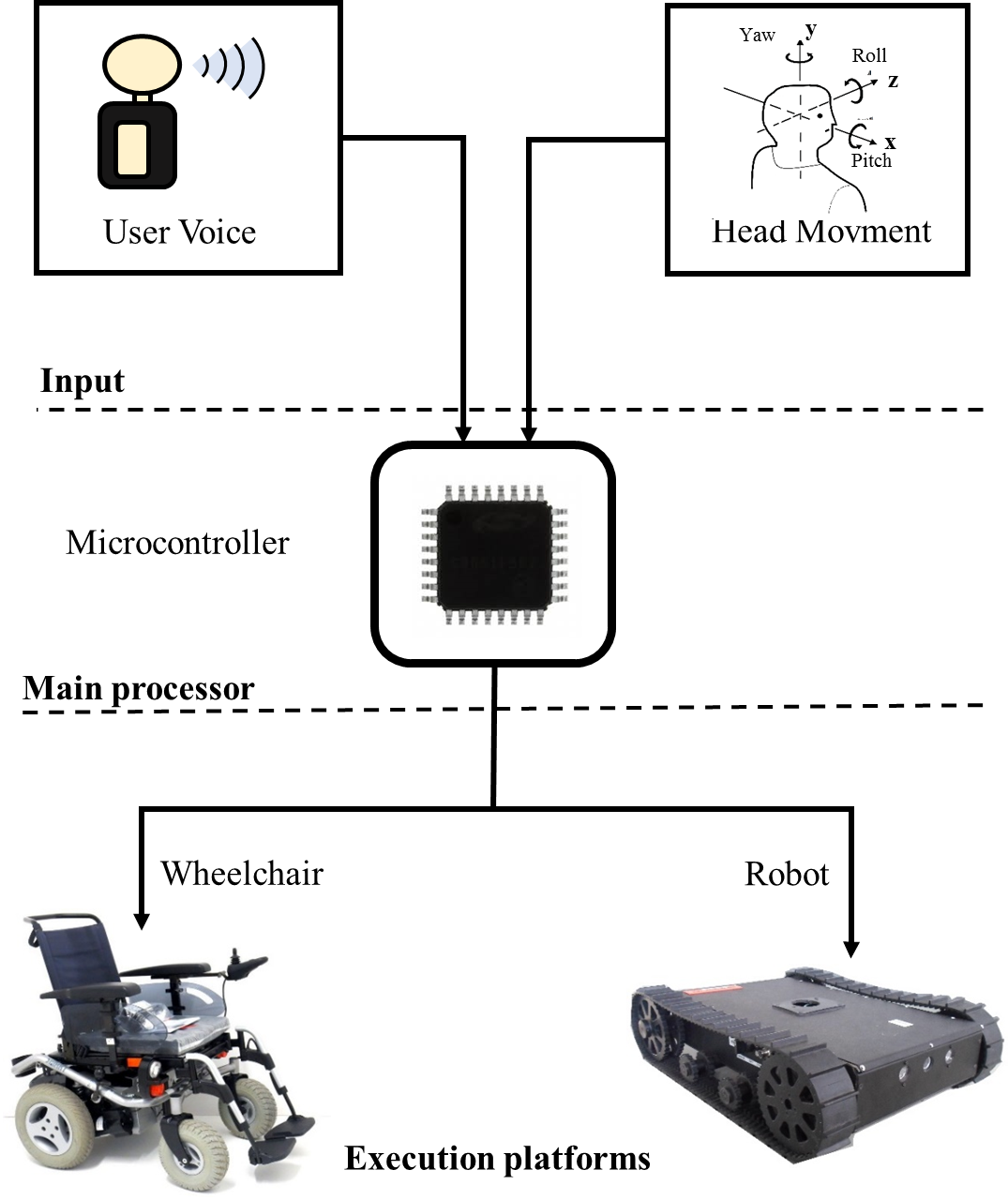 Figure 1: System structure.
2.1. Input Layer
The input layer deals with the signals and parameters picked up from the user body to generate specific control commands. It has two main signals from the wheelchair users which are the user voice command and the user’s head motions. There are two units for signal acquisition which are the voice recognition (VR) unit and the orientation detection (OD) unit. These two units are the main core of the voice and head tilt controllers.
The VR unit is a combination of two sophisticated modules using different voice recognition processors and algorithms. This makes the voice controller more reliable and allows the system to detect and eliminate the FP errors. The two voice recognition modules work together in parallel and send the VR results to the microcontroller as command index value using a universal asynchronous receiver/transmitter (UART) bus or by sending a binary value for a specific input/output port pin.
The first voice recognition module used in the voice controller is the Easy VR module which uses the strong voice processor RSC-4128 from Sensory, USA. The Easy VR module has the ability to operate in Speaker Dependent SD as well as Speaker Independent SI modes. The SD means that the system detects the voice command depending on the individual characteristic of the voice command. This makes the system respond only to the person who was trained before to the system. SI mode means, the system responses to any user giving the selected voice commands. For SD mode, the module uses the well-known Dynamic Time Warping (DTW) algorithm. The module uses the hidden Markov model (HMM) for the SI mode. The module can be trained with up to 32 voice commands.
The second module is the SpeakUP ClickTM module (MikroElektronika, Serbia). It only uses the DTW algorithm and is operating in SD mode only. This module can work standalone or with the host processor. It can be trained with up to 200 voice commands. More details regarding the used VR module can be found in [16-17].
The second acquisition unit in the input layer consists of two modern orientation detection sensors from Bosch sensor tech. Inc., Germany called BNO055. Both modules are identical and operate at the same bus speed and settings. They use I2C bus to communicate with the host processor; each module uses its own I2C address. The two modules are fixed in different locations on the system depending on the required orientation measurement. The first module is used to generate the motion control command. A traditional PC headset has been used to fix the first module in the middle of the headset. The second BNO055 module is used to detect the road slope or wheelchair reference orientation. It is fixed on the wheelchair chassis. The internal structure of BNO055 module includes 4 MEMS sensors combined with an ARM 0 microcontroller. The MEMS sensors are a gyroscope, magnetometer, temperature sensor, and accelerometer. A data fusion algorithm has been used to analyze the data from the four sensors and feeds the host processor by a ready to use orientation information in different measurement styles such as quaternion vector, linear acceleration, rotation vector, and Euler angles. In current work, the angle degree measurements of the Euler angles Pitch, Roll, and Yaw have been selected as input to the processing unit to represent the user’s head and reference orientation of the wheelchair [18].
2.2. Main processing Layer
The main processing layer interface between the input and output layers. The received information and data from the input unit are transported to the main processing unit using several communication busses and ports. The received data represent the user commands and is processed by the main microcontroller using a specific algorithm depending on the type of sensor sending the information. The results from the microcontroller will be converted to a specific hex-decimal message to control the wheelchair components. The Silicon labs EFM32GG990F1024 microcontroller has been used as the main controller of the system. Several sufficient input/output ports with wide types of communication buses have been embedded such as UART, I2C, USB, and general-purpose input-output pins GPIO [19].
One of the important tasks of this layer is to prevent the conflict between the modules and sensors in the input layer. The head tilt controller is activated as main controller when the system starts. The voice controller is activated for complementary functions such as controlling speed level and turning on and off lights and signals. The user can select the voice controller as main motion controller by giving the voice command “voice” and he can return to the head tilt as main controller using the voice command “orientation”. Fig. 2 shows the system flowchart and the transition between the sub-controllers.
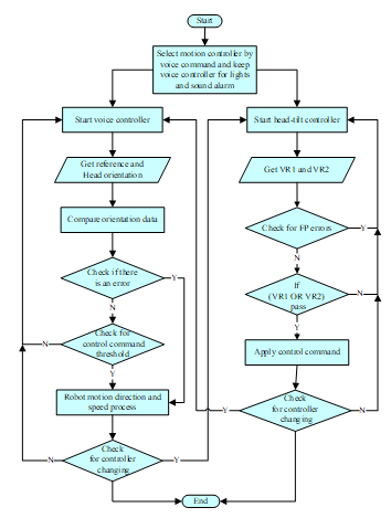 Figure 2: System flowchart
2.3. Output Layer
The output layer is responsible for the execution of the control commands. It is implementing motion commands for controlling the wheelchair electrical motors by changing the motors rotation direction and speed. In the presented system, the electrical powered wheelchair Meyra Smart 9.906 (MEYRA GmbH, Germany) is used as output or execution layer. The robotic motor driver Sabertooth 2×32 Amp (Dimension Engineering LLC., USA, see Fig. no. 3) has been used to control the wheelchair motors instead of original VR2 motor driver unit. The same motor driver unit has been used in jaguar lite robot and H20 robot which enables to use the system in robotic applications, too.
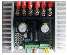 Figure 3: Sabertooth 2×32 Amp motor driver
3. System Description
In the presented work, the two sub-controllers are activated together to cover all the required wheelchair tasks. The head tilts controller cannot cover all the control commands of the wheelchair. It is mainly used for motion and speed adjustment control commands and not covers other commands like turning on and off lights or sounding alarms and signals. The voice controller was tested at different noise levels for several voice commands in [9], [14]. In this current work, it is used as an assistive controller with a few commands for controlling additional parameter.
The head tilt controller has two main orientation measurements, the first is the orientation of the user’s head which is responsible for generating the motion control commands. The generation of the motion commands depends on the value and the direction (the axis) of the head tilt angle. The second orientation measurement is for the reference wheelchair orientation. This measurement is used to calibrate the system in case of passing non-straight roads. The output of the orientation modules has been set in the form of Euler angles. Three Euler angles have been used to represent the body orientation around the main axes x,y,z using the tilt angles pitch (P), roll (R), and yaw (Y) respectively. The modules send the orientation data via I2C bus to the main microcontroller, which receives and processes the head and reference orientation information. The motion control commands are generated by specific motions of the user’s head. The speed and direction of the control command are determined based on the tilt axis for direction and the angle degree value for the speed. There are five main motion commands for controlling the presented system. Each command has specific regions of tilt angles to control the wheelchair motion. The forward command starts and ends by tilting the user head between (0°<P<25°) and (5°<R<45° and -45°<R<-5°). The left and right commands start from 0 to maximum speed by tilting the user head between (-10°>P>0°) and (5°<R<45° and -45°<R<-5°). The stop region is located between (-10°>P>0°) and (-5°>R>5°). The backward command tilt angles are located between (-10°>P>-45°) and (5°<R<45° and -45°<R<-5°). All other tilt angles are not used for generating control commands. This region is used for activating error messages in the system display or for activating emergency stop functions to protect the user and the system in specific cases such as the headset fall down or unexpected collision. Fig. 4 shows the programmed head tilt angles for the roll and pitch Euler angles.
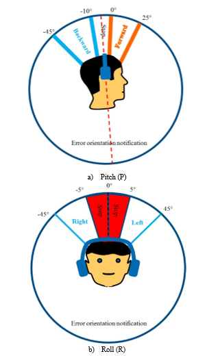 Figure 4: Control commands regions
4. Experimental Results
4.1. System Indoor Test
Several tasks have been tested to check the performance of the hybrid system. The tasks are divided into an individual task for each controller and for both controllers together. A group of complementary voice command has been tested such as “faster = increase the tilt to speed ratio”, “slower = set the tilt to speed to the basic ratio”, “light off = turn lights off”, “light on = turn lights on”, and “stop”. The head tilt controller was tested with the motion commands. 14 users tested the system with several tasks. All the 14 users are normal user without disabilities. The users used the system as quadriplegics patient without using their upper and lower limbs. Each task was repeated 10 times by all users. The tested tasks included the most important functions of the system. The tasks have been performed in a known path including a narrow corridor and a furnished laboratory. The test had two parts. In the first part, the wheelchair should be driven in a 1.5 m wide narrow corridor. In this part, the user should give the voice command “faster” to change the head tilt controller sensitivity from the primary speed 0°-25° P tilt angle à 0-2 km/h to the medium speed 0°-25° P tilt angle à 4 km/h (first task T1). In the second task, the user gives the voice command “light on” to activate the system lights T2. When the user reaches the laboratory door, he reduces the wheelchair speed sensitivity to the basic level using the voice command “slower” T3. Inside the laboratory, the user executes another group of tasks. The user needs to pass the laboratory entrance and avoid the collision with some obstacles (see Fig no. 5) T4. After driving the system and passing narrow corridor, the user needs to activate the emergency stop function of the head tilt controller by tilting his head beyond the programmed ranges for pitch or roll Euler angles T5. Then, the user needs to drive the wheelchair to the second laboratory door for exit. Before exiting, the user deactivates the system lights using the voice command “light off” T6. Finally, the user should exit the laboratory and stop the wheelchair in the outer corridor using “stop” voice command T7. The navigation map of the system tests is shown in Fig. 5.
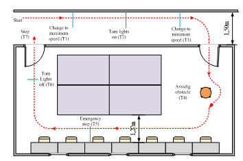 Figure. 5: System tests map
Table 1 includes the system indoor test results in the form of correct command execution (accuracy), the number of false positive error FP, and the number of false negative error FN for every task. The results clearly show that the head tilt controller performance is better than voice controller with 0 % errors and 100 % correct commands accuracy.
4.2. Reaction time test
The reaction time in this test refers to the time period between giving the command by the user and the complete execution of the command by the system in real time. Two parameters have been measured in this test which are the time and the distance. The three controllers, head, voice, and joystick were tested in the same environment with identical test parameters and conditions such as user weight, wheelchair speed, and the surrounding noise in the test environment. A fixed ≈ 1.716 km/h wheelchair speed was selected for the test for all three controllers. The wheel rotation per minute (RPM) was calculated and adjusted to 27.6 RPM individually for each controller using the digital tachometer DT-2234C. Only one user with a weight of app. 85 kg performed the test for the three controllers. All tests have been taken at the same laboratory with a surrounding noise of ≈ 54 dB.
The reaction time and the distance to stop the system are calculated using video frames from a high-speed camera. The camera can record the test video in a range from 30 to 1000 frames per second. The measured time period starts when the user gives the stop control command and finishes when the wheelchair stopped completely. The test has been repeated 10 times for each controller and the average reaction times and distances have been calculated. The same steps repeated identically for the head tilt, joystick, and voice controllers. The “stop” command was given in different ways depending on the used controller. The joystick controller has a specific joystick range for stop command which can be easily recorded by the camera. The voice controller will stop the system when the user gives the voice command “stop” and to make it easy to be recorded by the camera the user was asked to lift his hand up when he gives the “stop” command. Finally, for the head tilt controller, the camera can easily record the stop command which is activated by returning the user’s head to the range (-10°>P>0°, -5°<R<5°). Fig. 6 illustrates the capturing of the stop command frame for all controllers.
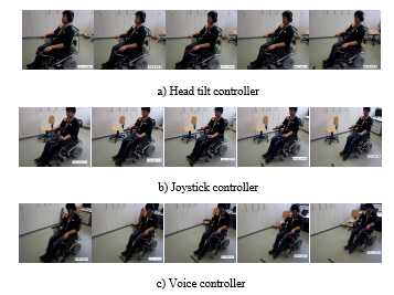 Figure 6: Stop command frames of the different controllers
Fig. 7 explains the statistical chart of the calculated reaction time and stop distance of the three controllers. The charts show the mean values for the measured parameter with the standard deviation (STDEV) for 10 samples for each controller. The results showed that the head tilts controller performance is better compared to the other controllers for the two calculated parameters.
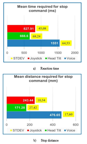 Figure. 7: Reaction time and distance for the stop command
4.3. Questionnaire
For the evaluation of the system usability, the fourteen users in the previous tests were asked seven questions about their feeling, adaptation, and opinions about the system. Each question should get a numerical evaluation from 0 minima up to 10 maximums. Table 1 summarizes the evaluation questions. Fig. 8 and Table 2 explain the questionnaire results.
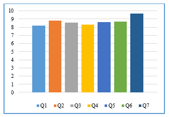 Figure 8: Questionnaire result for the system
Table 2: Questionnaire evaluation questions
| Question | Question |
| Q1 | Is it easy to use head tilt controller? |
| Q2 | How do you find the comfortability of wearing a headset? |
| Q3 | How do you find the reaction time for head tilt controller? |
| Q4 | How do you find the reaction time for voice controller? |
| Q5 | How do you find the voice command response? |
| Q6 | Is it easy to pass narrow area? |
| Q7 | Is it easy to control lights and signals? |
Table 3: Questionnaire results
| User | Q1 | Q2 | Q3 | Q4 | Q5 | Q6 | Q7 |
| U1 | 7,5 | 8 | 7,5 | 7,5 | 9 | 10 | 10 |
| U2 | 7,5 | 8 | 7 | 9 | 7,5 | 10 | 10 |
| U3 | 9 | 10 | 10 | 8 | 10 | 7,5 | 10 |
| U4 | 8,5 | 9 | 8 | 7,5 | 9 | 9 | 10 |
| U5 | 7 | 8 | 7,5 | 7 | 7,5 | 8 | 9 |
| U6 | 7,5 | 9 | 10 | 9 | 10 | 8 | 10 |
| U7 | 9 | 8 | 10 | 10 | 8 | 10 | 10 |
| U8 | 9 | 8 | 9 | 10 | 8 | 8 | 10 |
| U9 | 8 | 9 | 10 | 9 | 10 | 8 | 10 |
| U10 | 9 | 10 | 10 | 8 | 10 | 8 | 10 |
| U11 | 8,5 | 9 | 8 | 7,5 | 9 | 9 | 10 |
| U12 | 8 | 10 | 8 | 8 | 8 | 9 | 9 |
| U13 | 9 | 9 | 8 | 8,5 | 7 | 10 | 8 |
| U14 | 7,5 | 8 | 7 | 8 | 8 | 7,5 | 9 |
| Mean | 8,214 | 8,785 | 8,571 | 8,3573 | 8,642 | 8,714 | 9,642 |
| SDV | 0,726 | 0,801 | 1,206 | 0,928 | 1,063 | 0,974 | 0,633 |
The abbreviation STDEV refers to the standard deviation. The results of the questionnaire show differences in the system evaluation between the users. The highest mean value with the minimum standard deviation was observed for question Q7 (“Is it easy to control lights and signals?”). The highest difference between the users’ answers with a standard deviation of 1.206 was observed for Q3 (“How do you find the reaction time for head tilts controller?”). This may result from the fact, that the users were previously informed about the command confirmation function of the head tilts controller that makes a 100 ms delay in the starting of each motion command. The abbreviation STDEV refers to the standard deviation.
5. Conclusions
In this paper, the development and testing of a hybrid wheelchair controller have been described. The system consists of two sub-controllers which are the voice and head tilts controller. The voice controller uses two voice recognition modules combined to enhance the recognition accuracy and reduce the errors. The head tilts controller tests revealed a good performance in indoor as well as outdoor tests. The tests show that the head tilts controller is easier and more accurate in wheelchair controlling than the voice controller and it is thus selected to be the main controller. The combination of voice and head tilt controllers make the system more flexible and covers all wheelchair functions such as turning lights, sound alarms, and signals on and off. It also enables the selection of the speed range.
Acknowledgment
The presented work has been supported by the Iraqi Ministry of Higher Education and Scientific Research and the German Academic Exchange Service (DAAD, Germany).
- Henrik Vie Christensen A and Juan Carlos Garcia B,”Infrared Non-Contact Head Sensor, for Control of Wheelchair Movements,” Book Title Book Editors IOS Press, 2003.
- Farid Abedan Kondori, Shahrouz Yousefi, Li Liu, Haibo Li, “Head Operated Electric Wheelchair”, in Proc. 2014 IEEE Southwest Symposium on Image Analysis and Interpretation (SSIAI), San Diego, CA, USA, 6-8 April 2014, pp. 53-56.
- Mohammed Faeik Ruzaij, Sebastian Neubert, Norbert Stoll, Kerstin Thurow, “Auto Calibrated Head Orientation Controller for Robotic-Wheelchair Using MEMS Sensors and Embedded Technologies”, in Proc. 2016 IEEE Sensors Applications Symposium (SAS 2016), Catania, Italy, 20-22 April, 2016, pp. 433-438.
- Kazuo Tanaka, Kazuyuki Matsunaga, and Hua O. Wang, “Electroencephalogram-Based Control of an Electric Wheelchair”, IEEE Transactions on Robotics, Vol. 21, No. 4, August 2005.
- K. Tanaka, K. Matsunaga, and H. O. Wang, “Electroencephalogram-Based Control of an Electric Wheelchair,” IEEE Transactions on Robotics, Vol. 21, No. 4, pp. 762–766, 2005.
- I. Iturrate, J. Antelis, and J. Minguez, “Synchronous EEG brain-actuated wheelchair with automated navigation,” in Proc. of IEEE International Conference on Robotics and Automation (ICRA ’09), Kobe, Japan, 2009, pp. 2318–2325.
- Masato Nishimori, Takeshi Saitoh, and Ryosuke Konishi, “Voice Controlled Intelligent Wheelchair”, in Proc. SICE Annual Conference 2007, Sept. 17-20, 2007, Kagawa University, Japan, pp. 336-340.
- Aruna. C, Dhivya Parameswari. A, Malini. M and Gopu. G, “Voice Recognition and Touch Screen Control Based Wheelchair for Paraplegic Persons”, in Proc. Green Computing, Communication, and Electrical Engineering, Coimbatore, 2014, pp. 1-5.
- Mohammed Faeik Ruzaij, Sebastian Neubert, Norbert Stoll, Kerstin Thurow, “Hybrid Voice Controller for Intelligent Wheelchair and Rehabilitation Robot Using Voice Recognition and Embedded Technologies”, Journal of Advanced Computational Intelligence and Intelligent Informatics, Vol. 20 No. 4-2016, Fuji Technology Press Ltd, Tokyo, Japan, pp. 615-622.
- Satoshi Ohishi and Toshiyuki Kondo, “A Proposal of EMG-based Wheelchair for Preventing Disuse of Lower Motor Function”, in Proc. Annual Conference of Society of Instrument and Control Engineers (SICE), August 20-23, 2012, Akita University, Akita, Japan, pp. 236-239.
- Z. Yi, D. Lingling, L. Yuan, and H. Huosheng, “Design of a surface EMG based human-machine interface for an intelligent wheelchair,” in Proc. of 2011 10th International Conference on Electronic Measurement Instruments (ICEMI), Chengdu, China, 2011, pp. 132–136.
- Mohammed Faeik Ruzaij, Sebastian Neubert, Norbert Stoll, Kerstin Thurow,“Design and Testing of Low Cost Three-Modes of Operation Voice Controller for Wheelchairs and Rehabilitation Robotics”, in Proc. 9th IEEE International Symposium on Intelligent Signal Processing WISP2015, Siena, Italy, May 15 -17, 2015, pp. 114-119.
- Mohammed Faeik Ruzaij Al-Okby, Sebastian Neubert, Norbert Stoll, Kerstin Thurow, “Low-Cost Hybrid Wheelchair Controller for Quadriplegias and Paralysis Patient”, Advances in Science, Technology and Engineering Systems Journal (ASTESJ), Vol. 2, No. 3, pp. 687-694, 2017.
- Mohammed Faeik Ruzaij, Sebastian Neubert, Norbert Stoll, Kerstin Thurow, “Multi-Sensor Robotic-Wheelchair Controller for Handicap and Quadriplegia Patients Using Embedded Technologies”, ”, in Proc. 2016-9th International Conference on Human System Interactions (HSI), Portsmouth, United Kingdom, 6-8 July 2016. pp.103-109.
- Mohammed Faeik Ruzaij, Sebastian Neubert, Norbert Stoll, Kerstin Thurow, “Design and implementation of low-cost intelligent wheelchair controller for quadriplegias and paralysis patient”, in Proc. 2017 IEEE 15th International Symposium on Applied Machine Intelligence and Informatics (SAMI), Herl’any, Slovakia, 26-28 January 2017, pp. 399-404
- Speak Up Click User Manual Ver.101, MikroElektronika, Belgrade, Serbia, 2014.
- EasyVR 2.0 User Manual R.3.6.6., TIGAL KG, Vienna, Austria, 2014.
- BNO055 data sheet, [online]. Available: https://ae-bst.resource.bosch.com/media/_tech/media/datasheets/BST_BNO055_DS000_14.pdf. [Accessed: 15 Jun 2016].
- EFM32GG990 DATASHEET, [Online]. Available: http://www.silabs.com. [Accessed: 20 December 2015].