Implementation of a Robot Contest for Distance Education

Adv. Sci. Technol. Eng. Syst. J. 3(5), 161–165 (2018);
 DOI: 10.25046/aj030520
Robot contests are suitable for bachelor courses to gather hands-on experience in engineering diciplines such as mechanics, electronics and embedded software. After summarizing a concept of a robot contest for distance education (robot sumo) as presented in earlier publications this paper describes the implementation and first results of this concept. The contest is seperated into different tasks such as line detection and opponent location. As an example for transferring theoretical knowledge into a working prototype a simple sensor design for robot sumo is described and tested. Additionally a first student concept of a self designed robot is presented.
1. Introduction
This paper adds first implementation experiences to a robot contest concept originally presented at the 2017 International Conference on Research and Education in Mechatronics (REM) [1]. There it is shown that contests play an important role in education and in introduction of higher technology into the bachelor course [2], [3]. The presented concept is suitable for use in distance education where on-site laboratories are not readily available. Out of the evaluation of different contest formats robot sumo is selected as best suited. As an addition to this concept, that will be briefly summarized, this paper will describe the implementation of the contest into the curriculum at the Wilhelm Büchner University of Applied Sciences (WBU). To participate in a contest of robot sumo it is necessary to implement different strategies into a robot. To help students create their own solutions WBU has selected a platform compatible to the Arduino standard. Together with some prototyping parts this platform is given to the students during the project phase in the 7th semester in the module “Project Study for Engineers”. The different solution out of these projects will enter into a future contest at the WBH where they will compete against standard implementations that can be purchased. To illustrate the use of creative solutions an innovative sensor implementation is shown to locate and range the opponent. Measurement data and tests are shown to evaluate the performance of the sensors. Finally, a robot is presented that was developed and made by a student during his bachelor thesis. This robot is entirely made by 3D-printing and shows, what can be achieved within the three months available for both the bachelor thesis and the project study.
2. Contest Concept
The original paper [1] evaluated different robot contest formats. The criteria were robot size, arena size, budget, complexity, time to completion and research potentials. Robot Sumo in the mini class has been selected as it seems the most suitable for table top and home development [1].
3. Robot Sumo
The contest is based on the traditional Japanese game of sumo wrestling (jap. 相撲 Sumo) where two contes-¯ tants try to push each other out of a circular ring (jap. 土俵 Dohyo). The contestants start behind two lines¯ in the middle of the ring (jap. 仕切り線 Shikirisen = Shikiri lines) [4].
There are 28 articles in the unified sumo rules making this a well designed contest [5]. Figure 1 is showing a typical Sumo match situation where one robot is pushed over the edge and touches the ground outside the ring and thus loses this round.
In order to compete in a robot sumo contest the robot must implement different strategies. These are often divided into the different domains of mechanical, electrical/electronical, and software. There are three major strategies to a robot sumo match:
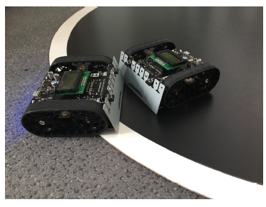 Figure 1: Typical Sumo match situation (picture: Eiken Luebbers)
3.1. Do not leave the ring
The robot that leaves the ring first will loose the round. Thus it is important to detect the ring border so that the robot will not leave the ring by itself while moving. The rules ask for a black surface of the ring and a 2.54 cm white line around the border (mini class). The most common strategy is to detect the change in reflectance between the black and white surfaces and move backward or turn to avoid leaving the ring. Reflectance sensors are inexpensive and most will provide a digital signal that can be easily processed by microcontrollers.
3.2. Locate your opponent
The most important strategy is to locate the opposing robot so that it can be targeted with the actors. The solutions vary from moving randomly around the ring until an acceleration sensor registers a collision to LiDAR-Sensors that will determine the exact location and range. All strategies aim to put the opponent in front of the own robot so it can be pushed out of the ring. A simple but efficient implementation of this strategy will be described later in section 6.
3.3. Push the opponent out of the ring
This strategy seems to be the most straightforward implementation: Move in the direction of the located opponent. But it can be subdivided into mechanical parts such as blades, that can lift the opponent so it will loose traction and motors that could combine traction and momentum. The mechanical and electromechanical design will be part of the outlook, a first implementation can be seen in section 7.
4. Robot platform
Not all students have the experience, time, or knowledge to design a complete robot system. To concentrate on the chosen strategy in the project a platform is provided by the WBH to help the students with an easy start into development. First experiences show that there are some groups that concentrate on software, some on sensors and others on mechaical design.
The platform is a commercially available robot specifically designed for the robot sumo mini class. It is an electromechanical platform that includes the power supply out of four AA-batteries, downward oriented reflectance sensors for the ring edge detection, general purpose inertial sensors, the motor drivers including metal-gear motors, and a differential rubber chain drive. It also includes an Arduino-compatible interface to add a microcontroller and/or sensors.
When students sign up for the project study
(see section 5), the WBH will provide two of these platforms together with two Arduino compatible microcontroller-boards, two mini-breadboards for rapid prototyping and a number of wires with headers for quick installation of sensors. No soldering is necessary to get started with the platform and first implementations.
5. Project Study for Engineers
The project study has been identified as the proper format for the robot sumo development in [1]. The students learn project management principles and team work. And it must have a measurable outcome within a 3 month time frame. When working on a robot during the module “Project Study for Engineers” the students gain practical knowledge in mechatronic systems. The robots need mechanics, electronics and software to function. Students need to research the current technologies and methods and implement them into the contest. Furthermore, the project needs to be managed in time and within a given budget. This adds economic sciences and industrial engineering to the contest. And finally the project needs to be productive for a live contest at a certain interval, adding working under pressure to the picture. All this teaches the students to be productive in future jobs.
6. Sensor Solution
To demonstrate a creative solution for the strategy of “locate your opponent” the implementation in another commercially available platform is analyzed. This platform adds a microcontroller and infrared proximity sensors to the platform described in section 4. It combines an inexpensive standardized electronic hardware with a non-standard control by software to combine detecting and ranging of an object.
6.1. Sensor Electronics
The basis for the hardware is the digital proximity sensor TSSP77038 (Vishay Semiconductors) as it is used e.g. in automatic water fountains [6]. The sensor has a digital output active-low interface for microcontrollers to signal if an object is detected or not. The sensor is sensitive for infrared light of a certain bandwidth, the typical wavelength is 940 nm. The sensor eliminates interferences from natural or artificial light by detecting only modulated infrared light with a frequency of 38 kHz. To illuminate an object that can be detected, an infrared light emitting diode (IR-LED) is driven with a carrier frequency of the same 38 kHz. If enough modulated infrared light is reflected from an object onto the sensor, the output is driven to low to signal an object in range of the sensor.
To add a relative range detection the light amount of the emitting diode is varied using a pulse-widthmodulation (PWM) as an envelope function. This allows to control the output power of the diode and thus the amount of reflected light. If an object is detected with the full power of the diode and the power is then stepwise reduced, a relative range of the detected object can be determined. The amount of power when the object is no longer detected is a measure for distance. The less power is needed, the closer the object is. If used with a single emitter and single sensor a one dimensional measurement is possible.
The typical information needed for the strategy “push the opponent out of the ring” is to know, if the robot needs to turn left or right to face the opponent directly with its front so when driving forward, it will hit the opponent an can push it in front of it. To be able to have this twodimensional information the robot needs at least two emitter/sensors combinations.
The implementation actually uses three sets of emitter and sensor. One facing front, one facing left, and one facing right. Each set is controlled individually by the software.
6.2. Control Software
Each infrared light emitting diode can be individually controlled by software via PWM to send out a certain amount of light modulated with 38 kHz. Each sensor gives back the information, if enough modulated light in its field of view has been detected. Sending only light to the left will illuminate objects that are left of the robot. The right sensor should “see” significantly less light than the left or front sensor, depending on the position of the reflecting object.
6.3. Measurement Results
To test the strategy a white object was placed at certain angles and distances to the robot. The relative distances of each sensor where recorded to se if this concept can detect direction and distance of an object. The PWM can be controlled in 6 levels, where 1 has the highest power output and 6 the lowest. The object was placed in 20 degree intervals around the center of the robot. The results are shown in figures 2, 3, and 4. Both upper graphs show that the range can be clearly distinguished. Also it can be seen that each sensor has a certain field of view. The bottom graph shows the overall detection capability of a white object placed at a 10.5 cm distance. But it also shows that there are certain blind spots between 40 and 60 degrees each left and right of the front. The blind spot at the rear is expected as there are no LEDs or sensors here.
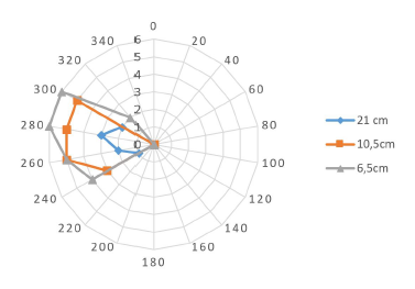 Figure 2: Measurements results left LEDs/left sensor
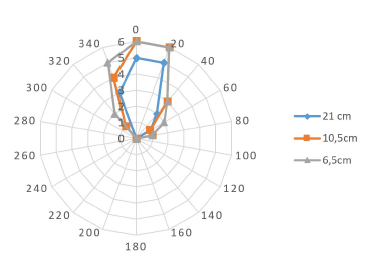 Figure 3: Measurements results middle: right LEDs/front sensor
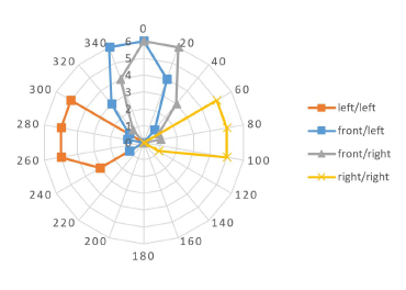 Figure 4: Measurements results bottom: all LEDs/sensors
It was shown, that the sensor concept can detect relative distance and direction of the opponent. When the front sensor shows the same distance when left and right LEDs are used, it can be assumed, that the object or opponent is directly in front of the robot (see figure 4 bottom graph at 0 degrees). This information can then be used in the next step where the motors are controlled to move the robot in the right direction. If the detection logic is used continuously the robot can also follow moving opponents.
7. Student Robot Solution
After showing a possible solution with an existing hardware it requires further consideration if it is possible for students to actually complete a robot construction within 3 months that are available for the project study. A student at the WBH has therefore been given the task to design and build a complete robot system with the use of a 3D-printer.
The first task was to analyze potential techniques for sumo robots [7]. The fields of traction (e.g. 2 wheel drives vs. 4 wheel drives), shields and shovels (for protection or to lift the opponent), ropes (to keep other robots at distance), flags (to trick the opponent to follow the flag) or size (keep below the line of sight of the opponent) were analyzed. Additionally the sensor technology was researched. Inertial sensors, several distance sensors, reflection sensors and cameras were described. The research was completed with a look into the Arduino platform and 3D-printing.
For the actual prototype an architecture was developed and the proper components were selected. For the traction a rubber chain differential drive was chosen. This allows the robot to distribute all its weight onto driven wheels or chains respectively to have the maximum traction within the allowed weight range. The force with which the robot can push (“traction”) is the frictional force that the driven wheels can generate. This is proportional to the weight of the robot (normal force) at the contact between driven wheel and ring surface (Amontons’ First Law). If the robot had only two driven wheels and one or two support wheels then some of the weight rests on the passive wheel(s) and cannot support the friction of the active drives. A chain drive is easier to implement as 4 wheel drive and still distributes all weight onto the driven components.
Out of his research the student chose Time-of Flight (ToF) laser sensors. These sensors determine the distance to an object by measuring the time a laser pulse needs to travel to an object and back. The sensor used is the “world’s smallest ToF sensor” from STMicroelectronics [8]. It is a sensor system in one housing combining a laser diode with a detection circuit using an single photon avalanche diode array and an on-silicon processing unit. It communicates via serial interface with a host controller.
The mechanical parts are 3D-printed. Figure 5 shows the finished robot. Motors and gears were purchased as were the electronic components. In total the price of the robot was about half compared to the commercial product while having more flexibility in design, sensors, and computing power. The shown robot uses two arduino controllers boards that process sensors and mechanics separately and communicate with each other via an onboard network.
8. Summary and outlook
In addition to the original paper presented at the 2017 International Conference on Research and Education in Mechatronics (REM) [1] where the concept of robot sumo for distance education is explored this paper adds some practical measurements and a student solution to the concept. The first competition will add a major milestone to this concept of learning. Students will have completed a project where the robot is able to compete in robot sumo. Different strategies in terms of mechanics and tactics will be the source of future publications. After showing what is possible for one student within 3 months the project was officially offered at WBH for the project study in the bachelor courses in Spring of 2018. The project has been promoted by newsletter and YouTube-videos [9]. Since launch the commercial platform has been supplied to a number of teams that are now designing and testing their robots. The first competition will be held at the end of 2018 when at least 4 teams have completed the project. The competition will be supplemented by 4 standard robots that are comercially available. The competition will be recorded and published on YouTube.
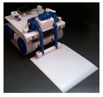 Figure 5: CAD parts and complete 3D-printed robot (source: [7])
- E. Lübbers, D. Schoen, “Robot contest concept for distance education” in 18th International Conference on Research and Education in Mechatronics (IEEE), Wolfenbüttel Germany, 2017. https://doi.org/10.1109/REM.2017.8075253
- T. Verhoeff, “The role of competitions in education” in Future World – International Conference & Exhibition, 1997. [Online]. Available: http://olympiads.win.tue.nl/ioi/ioi97/ffutwrld/competit.pdf
- A. Kolmos, “Problem-based and project-based learning” in University Science and Mathematics Education in Transition, O. Skovsmose, P. Valero, and O. R. Christensen, Eds. Berlin: Springer-Verlag, 2009, pp. 261–280.
- Wikipedia, “Sum¯o”, 10.05.2017. [Online]. Available: https://de.wikipedia.org/w/index.php?oldid=165000523
- Robotics Society of America, Inc, “Unified sumo robot rules”, 2015. [Online]. Available: http://robogames.net/rules/allsumo. php
- Vishay Semiconductors, “IR Sensor Module for Reflective Sensor, Light Barrier, and Fast Proximity Applications”, 2018. [Online]. Available: https://www.vishay.com/docs/82470/tssp770.pdf
- A. Kusmin, “Entwicklung einer autonomen Roboter-Plattform für Roboter-Sumo”, Bachelor Thesis, Wilhelm Büchner University of Applied Sciences Pfungstadt Germany, 2017.
- STMicroelectronics, “World smallest Time-of-Flight (ToF) ranging sensor” 2018. [Online]. Available: https://www.st.com/content/st_com/en/products/imagingand- photonics-solutions/proximity-sensors/vl53l0x.html
- YouTube, “Roboter-Sumo – Wilhelm Büchner Hochschule”, 2018. [Online]. Available: https://youtu.be/8qtDo-sM_0s
No related articles were found.