FPGA Implementation of Ultra-High Speed and Configurable Architecture of Direct/Inverse Discrete Wavelet Packet Transform Using Shared Parallel FIR Filters
 , Mohamed Tabaa 2, Fabrice Monteiro 1, Juliana Srour 3, Abbas Dandache 1
Adv. Sci. Technol. Eng. Syst. J. 3(5), 116–127 (2018);
 DOI: 10.25046/aj030516
This work presents new pipeline-parallel, generic and configurable parallel hardware architectures for the Direct/Inverse Wavelet Packet Transform (DWPT/IDWPT) independent of any specific family of wavelets, implemented in FPGA technology using a parallel architecture of direct FIR filter. We propose in the following paper, new P-parallel structures for the DWPT and IDWPT transforms based on the Mallat binary tree algorithm. Therewith, we developed a P-parallel/modified direct FIR filter architecture using pipeline-parallelize and hardware resource sharing, which provides not only ultra-high speed data processing but also a limited amount of hardware as resources are shared between filters and the bidirectional wavelet packet transformation. This model follows two important strategies: I) a powerful structure pipeline/P-parallel using strict data management and interleaving, II) sharing hardware at different levels in the transformation and between the two DWPT/IDWPT transformations. These architectures are modeled in VHDL at RTL modeling level. They are generic and fully configurable: at synthesis and post-synthesis. The simulation results show an acceleration of data processing to an approximate value of P-Parallel multiplied by frequency with lower used resources. Furthermore, the impact of tree depth and filters order on throughput is very light due to the linearize architecture of our model. The synthesis was achieved using the Intel Quartus Prime Lite Edition software and targeting the Intel Altera Cyclone FPGA technology.
1. Introduction
1.1. Sate of art
Wavelet transform are considered the rightful heir to Fourier transform, since they are the best signal analysis tool in time and frequency domain.
From a historical point of view, the founder of the wavelets world was J. Morley in 1980 who developed a new transform called “Wavelet Transform (WT)” to solve the limitations of the different versions of the Fourier transform on signal analysis passage from the time to the frequency domains [1, 2]. The numerical application of the wavelet transform is born with the work of Morley and Grossman [3], while the idea of wavelet seems to originate in the work of Gabor and Neumann in the late 1940s. Mallat [1, 4], Meyer [5], Chui [6], Daubechies [7] and others, contributed the pioneering work reported in the early monographs.
The discrete version of the wavelet transform called “Discrete Wavelet Transform (DWT)” mixes both the notions of time and frequency scaling using a compact kernel (bit wave = Wavelet). Mallet [1] generalized the discrete wavelet transform that introduce more flexibility on the time scale of data analysis and lead to the concept of Discrete Wavelet Packet Transform (DWPT).
Currently, the architecture of DWPT and Inverse DWPT (IDWPT) are unsuitable in most fields like image processing, video processing, noise reducing, encryption, coding, modulation and others. This explains the large number of researches and restrains the usage of DWPT in large applications domains, which leads us to develop a new hardware architecture to improve the performance of hardware implementation of DWPT/IDWPT. The major challenges for modern systems can be summarized as: (i) high throughput rates (increasing the volumes of data processed, especially in multimedia application) and (ii) low cost hardware (limited amount of hardware resource) while still providing high performance.
1.2. Related works
Abundant researches can be found in the literature about the hardware implementations of wavelet packet transform. The first work related to the hardware implementation of DWT was recorded in 1994 [8] Denk and Parhi described an orthonormal DWT architecture, which used a lattice Quadrature Mirror Filters (QMF) structure and digit-serial processing techniques. Similarly, Hatem et al. [9] proposed a parallel/sequential QMF architecture in VLSI for the DWT, to reduce the overall numbers of multipliers. After that, the research evolution was started.
Since DWPT retains all the advantages of the discrete wavelet transform, it has becomes an essential standard tool for signal, image and video processing. For this reason, the DWPT topic has attracted a lot of attention in research area. Notably, the most implementations of DWPT are based on the concept of FIR (Finite Impulse Response filter) filter banks [10]. In the literature, many works are addressing the implementation of DWPT/IDWPT in hardware devices such as Processors, GPUs (Graphic Processing Units) or FPGAs, to take full advantage of the powerful and flexibility offered by the DWPT. In this context, the year 1999 viewed the first work to implement the DWPT on a processor [11] but in the last recent years, FPGA became a popular target technology for many works, which become doubtlessly the target implementation technology for DWPT and IDWPT. However, the implementation of DWPT/IDWPT (based of FIR filter banks) has many caveats, which make it hard to fulfill a high throughput rate and low area consumption simultaneously.
To fulfill these challenges, many works implement the DWPT or IDWPT transformations on FPGA like the work of Wu and Hu [12], the authors implemented DWPT/IDWPT using Embedded Instruction Codes (EIC) and strict number of multipliers and adders for the symmetric filters (two multipliers and four adders). In [13], IDWPT architecture was presented based on classical recursive pyramid algorithm (RPA) by using lifting transformation and polyphase decomposition. In [14], a fast and configurable DWPT was presented based on FIFO inputs, dual-port memory, multipliers and adders.
An inspirational architecture of DWPT was presented in [15] by implement the tree algorithm, their implementation on FPGA was discussed in [16]. In [17], the same authors based on two modes developed pipelined architectures of the direct and inverse DWPT transform: serial-word mode and parallel-word mode. In [18], Farahani and Eshgho presented word-serial pipeline architecture of DWPT/IDWPT transforms by using parallel filter structure. To speed up the transform, the same authors updated their architectures by using high-pass and low-pass filters. In addition, they implemented the wavelet packet transform on FPGA by using three types of multipliers [20].
To increase the performance, in [21] a VLSI architecture of DWPT was presented which based on frame-partition architecture. In [22], authors implemented a flexible architecture of DWPT and IDWPT based on register interface and a multiplexing structure.
An algebraic integer architecture of Daubechies DWPT was presented in [23], this architecture was developed to compute one and two dimensions of Daubechies wavelet order 6 (Db6) with adder-less.
1.3. Contributions
This rich literature around DWPT and IDWPT reveals the importance of wavelet transforms in the current and future applications, which motivates us to deeply excavate in DWPT/IDWPT research area. Furthermore, most of recent approaches present some advantages in terms of flexibility, scalability, reliability, or low costing but not all together within the same architecture.
However, our aim is to develop new architecture generic and configurable (in synthesis and post-synthesis) of DWPT and IDWPT, which can provide an ultra-high speed data processing with minimum hardware usage. We already proposed our first pipeline and configurable architecture of DWPT in 2015 [24] and of IDWPT in 2016 [25] based on Mallat binary tree scheme [4] without any presence of parallelization tools. We transformed successfully an exponential algorithm of DWPT/IDWPT, based on classic Mallat binary tree, to a linear algorithm with the conservation of sample speed processing but with decreasing the usage of hardware by a smart managing and interleaving of data along the depth of transformations.
To increase the throughput, we propose in this literature massive pipeline-parallel architectures of DWPT (P-DWPT architecture) and of IDWPT (P-IDWPT architecture). Moreover, a massive pipeline-parallel DWPT-IDWPT architecture with massive sharing of resources: the core of the architecture is based on sharing hardware resources between P-DWPT and P-IDWPT transforms, and also based on a smart sharing of computational resources (multipliers and adders) between the approximation/details functions related to filter banks.
Those architectures are generic and fully configurable relative to the tree depth, the filters order, the quantization, and selection way of processing method (P-DWPT or P-IDWPT).
To evaluate the performance of our architectures, we study the effect of four parameters: “degree of parallelization, transformation depth of DWPT or/and IDWPT, order of low-pass and high-pass filters, and order of quantization” on the “operating frequency or throughput rate” (computational performance) and “resource consumption” (used hardware or hardware cost). Furthermore, we compared our synthesis results with the existing in literature.
1.4. Paper organization
The rest of this literature is organized as follows: Section II, presents a brief overview of wavelet packet transform concepts and the main challenge of parallelization in our context. Section III is dedicated to present our proposed pipeline-parallel architectures and related design paradigms. Then, we summarize the results obtained for these architectures on FPGA implementation. At the end, we finalize with the comparison, conclusion and the perspective works.
2. Background
From mathematical point of view, wavelet packet transform decomposes the signal into a two sub-signals: detailed signal and approximated signal. To achieve the transforms there are several methods, the famous one is the multi-resolution or multi-cadence analysis algorithm proposed by Mallat [1], which called “Mallat binary tree” or “pyramid algorithm” of wavelet packet transform. This multi-resolution analysis is based on cascade of low-pass and high-pass digital FIR filters. By definition, using Wavelet Transform (WT) theory is that each signal can be presented by projecting it into a series of scaled and translated functions . The original single function is called “Mother Wavelet” and all scaled and translated functions are obtained by translation and expansion of the mother function, as presented in equation (1):
The value of affects strictly the bandwidth of Mother Wavelet. When s is less than 1 ( ), wavelet variance decreases and the basis function contracts (used to analyze the high frequency signal). While for , wavelet variance increases and the basis function stretched (used to analyze the low frequency signal).
The Continuous Wavelet Transform (CWT) of is defined as:
where * denotes a complex conjugation.
From the wavelet theory, the CWT is too redundant that make it impractical. To solve this problem, in 1992 Daubechies [26] create discrete wavelets transform (DWT) from the CWT by discretizing of scalable and translatable variables as shown in equation (3):
Where the number of wavelets coefficients is finite. To discretize the scalable and translatable variables, we use the dyadic sampling concept that mean we usually choose and (give us a dyadic sampling in time). The Discretize of the translation and dilation contraction parameters of the wavelet in (2) leads to DWT presented in (4):
Another important function called “scaling function” is similar to the wavelet function . According to the multiresolution wavelet theory, the is decomposed into finer and finer detail (in multiresolution stairs). As seen in equation (5), the has also two integer subscripts or parameters and .
where specifies the magnitude as well as the scale of the function, and specifies the position (integer location, translation or shift) of the function.
In fact, DWT in signal analysis theory can be implemented with a different ways that is presented in equation (4) by using the concept of non-uniform filter bank. The filtering operation of input signal is done iteratively and generates two separates sub-signals with two different spectrum, the upper half of the spectrum contains the high frequency component of input signal which is analyzed by the wavelet function and the lower part contains low frequency component of the same input signal which is continued to the next stage. The corresponding obtained coefficients that present the first filtered signal are called detailed coefficients and the second filtered signal are called smooth coefficients. Classically, both low-pass digital filter and high-pass digital filter are obtained from the scaling function and their corresponding mother wavelets.
We suppose and like a FIR filters non-recursive with length, the transfer functions of and can be represented as follows:
The orthogonal multiresolution decomposition of DWT can be carried out efficiently by using Mallat tree algorithm or pyramid algorithm [1]. This structure constitutes a bank of filters in QMF analysis, where the scaling functions and wavelet functions are realized using scale relations (6) and (7) and can be given as: forms the set of scaling functions and their corresponding wavelets. The suffix denotes the number of wavelets and is dubbed as multiplicity.
According to the wavelet theory based of filter bank concept, any arbitrary signal can be expanded into a sum of scaling and wavelet functions. The discrete wavelet transform of target signal is given by:
2.1. DWPT under focus
The decomposition DWPT at each resolution level, based on Mallat binary tree, can be presented as tree shape. To demonstrate a general transform of DWPT based of Filter Bank concept, we use Figure 1.
The input signal ( ) in coming data level will be decomposed into a high frequency signal (smooth or approximation coefficient ) and a low frequency signal (detailed coefficient ) in level by using low-pass / high-pass filters respectively. Then data path will be down sampling by a factor of two (lead to half size of original signal) and so on for the other levels (number of level equal the depth in Mallat tree algorithm). As a global view, the corresponding wavelet coefficients in different level are derived as follows:
where and and are low pass and high pass filters, respectively.
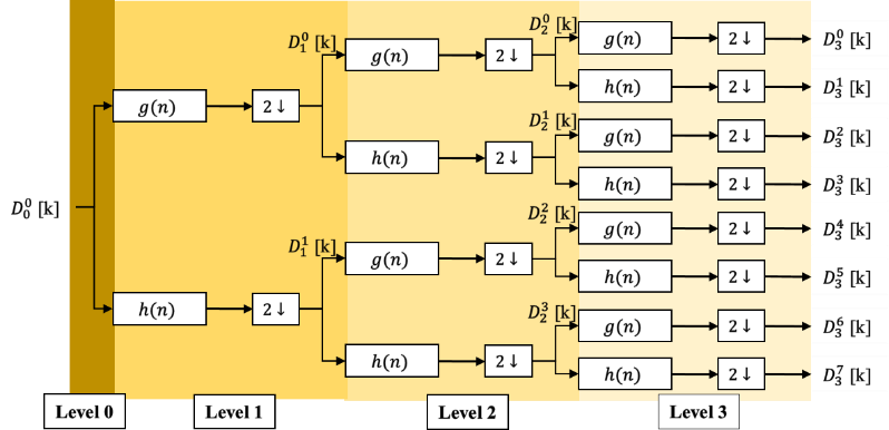 Figure 1. Three-level DWPT decomposition tree
Considering the FIR (Finite Impulse Response) non-recursive implementation scheme of length for the and filters, the corresponding transfer functions can be represented as equations (6) and (7). The number of filters coefficients depends on the mother wavelet. The choice of this later depends upon the required application and its properties. Examples are Daubechies family where the filter length is (Order N is strict positive integer), and Coiflets family where the filter length is (Order is strict positive integer), etc.
2.2. IDWPT under focus
From the wavelet theory, the reconstruction of original signal that decomposed by direct DWPT is achieved by using the inverse of wavelet packet transform (IDWPT). Like the direct way, the reconstruction operation is also performed by using an iterative method. This mean, for each pair coefficients at level of the tree we can calculate the wavelet packets coefficients at the previous level as shown in equation 13:
In sample representation of equation (13), it can be represented in Figure 2.
For example to reconstruct the coefficient at level , we used the approximation and detailed coefficients at the previous level . The reconstruction operation is provided by adding zeros and convolving the results with the reconstruction filters.
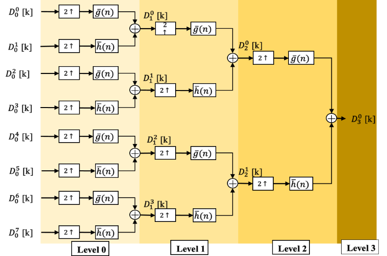 Figure 2. Three-level IDWPT reconstruction tree
To perfectly reconstruct the original signal (before the DWPT transformation), it is sufficient to use the concept of QMF filters that satisfy the following relations:
Where and are the low-pass and high-pass reconstruction filters for IDWPT.
2.3. Parallelization challenge of DWPT and IDWPT
In order to achieve our aim to develop a high performance hardware architecture of DWPT and IDWPT, we think for the first time by a classic way to parallelize the Mallat binary tree as shown in figures 3 and 4.
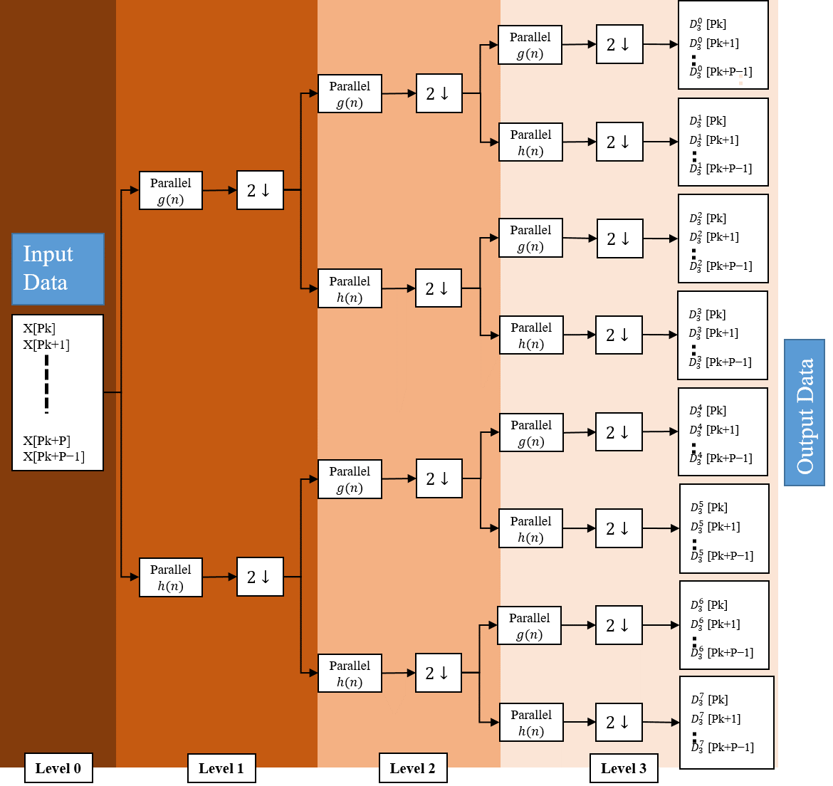 Figure 3. Classic P-parallel, Three-level DWPT
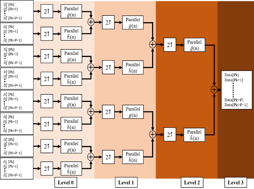 Figure 4. Classic P-parallel, Three-level IDWPT
A traditional possible parallelization solution is presented in figures 3 and 4, where we show a three-level decomposition, reconstruction tree respectively, with theoretical P-parallel degree and a P-parallel filters bank consists of wavelet functions to be able to treat P sampling in each slot time. This classic P-parallel architecture is unrealizable because the number of reconstruction filters and/or decomposition filters increases exponentially as a function of depth order. In precision, the number of filters needed to implement this architecture is around . For example, with degree of parallelism and , we need 1008 low/high pass filters for DWPT and another 1008 low/high pass filters for IDWPT. The implementation of 2016 filters is a potential problem, which make it unable to implement.
3. Our Parallel-Pipeline architectures with sharing resources
Considering the diagram in figures 1 and 2, a zoom on data flow on the classic Mallat binary tree leads us to some regularity function:
- At a given stage of the Mallat binary tree, the data rate processed by any filter is twice as fast as that of any filter on the adjacent stage on the input side in Figure 1.
- While, the data rate processed by any filter is twice as slow as that of any filter on the adjacent output-side stage in Figure 2 (factor 2 upper sampling from stage to stage).
- In addition, the amount of data processed in a k-level is times the amount to process at level 1. Thus, the total amount of data to be processed in level is the same as in the first or last level ( ).
Based on this big regularity that provide high throughput rate with lower hardware resources, we build an evolution parallel-pipeline architecture of DWPT and IDWPT based on Mallat binary tree as shown in section III. To achieve our objective that ensure high throughput with low hardware consumption in our parallel architecture of DWPT and IDWPT, we have to modify the high/low pass FIR filters.
Under the strategy to reduce area consumption, instead of using two filters we merge in the same architecture the functionality of low-pass and high-pass filters in a single block filter. Furthermore, we modify the single block to process P sampling in two-clock cycle. In figure 5, we present our P-Parallel modified transposed FIR filter.
This new architecture is linearized to be similar to coding theory where the Serial transposed FIR filter is like a Single-Input Single-Output (SISO) system and the Parallel transposed FIR filter is like a Multiple-Input Multiple-Output (MIMO) system. Therefore, this heterogeneous architecture provides the processing of P inputs signals and consequently P outputs signals, in each clock cycle.
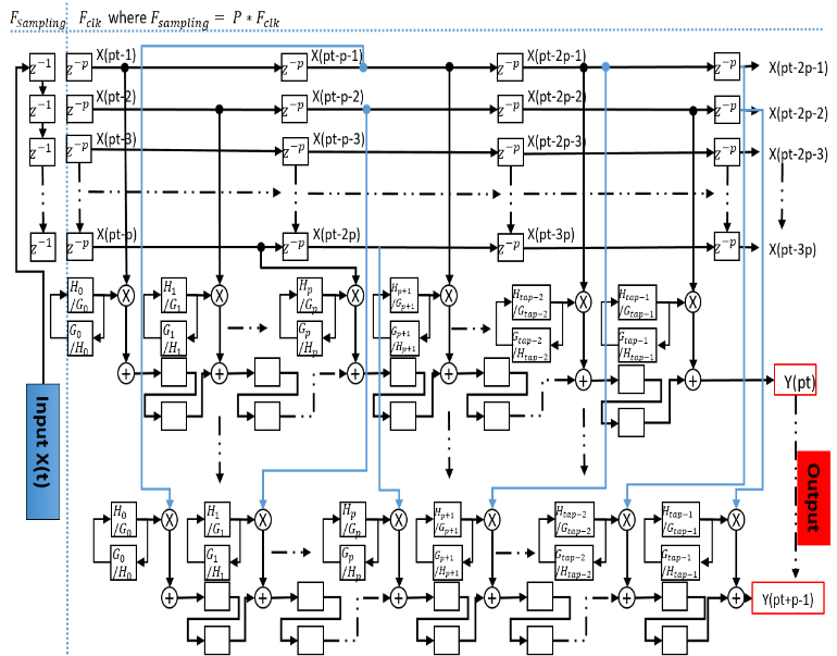 Figure 5. Architecture of a single modified FIR filter
The main difference with the filters, proposed in [24, 25] is related to the handling of the low-pass and high-pass filter coefficients. Furthermore, this filter requires to be feed by correctly scheduled data by a smart shift of data between different stages to serve P sampling in each clock cycle.
Respecting the buffer order, it is the most sensitive and the core of the serial FIR filter to parallel operation. This role of manage and interleaving data is devoted to the key block in our model. We called this block “buffers block” situated between the filters in different level. The structure of a single buffer is dependent on the direct or inverse DWPT.
In our following proposed architecture, we respect these constraints:
- Our developed architecture is based on the Mallat binary tree where we use the theory of filter bank to decompose and reconstruct the original signal.
- The degree of parallelism and the characteristics of the target card (technology) must be taken into consideration in order not to deposit available resources.
- The degree of parallelism must respect the dyadic rule, that is, . Where affects directly the data managing between different levels of the transformation tree and simplifies the up/down sampling operation.
- To synthesis our proposed hardware architecture, we used Altera Quartus premium lite edition software that is targeted on Altera FPGA belonging to the Cyclone V family with a speed grade of –7.
3.1. First proposed architecture: Parallel-Pipeline architecture of DWPT with sharing resources
This part is dedicated to present a P-Parallel DWPT architecture, which provides high throughput, by using the modified transposed P-parallel digital FIR filters (presented in figure 6).
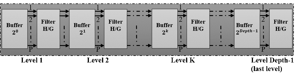 Figure 6. Data path diagram of the proposed P-parallel DWPT architecture
As we mention below, this modified filter or block, presented in Figure 5, ensures the processing of the same amount of data on any stage in the original Mallat binary tree.
Concerning our plan to reduce the hardware usage, the functionality of high-pass filter and low-pass filter is provided by the blocks. Consequently instead of using two separate similar filters (high-pass filter and low-pass filter), we propose using a single filter in an alternatively process. Hence, this alternatively process (on consecutive clock cycle) works by taking a sample for the and then for and so on. The critical point in this model is to manage correctly the data between filters and different levels, this role is devoted to a specific buffers situated between the filters in different stages. The structure of blocks buffer is shown in figure 7.
A. Buffer Block structure of DWPT
The parameter in figure 7 is related to the number of the stage in which the buffer is implemented. Then in each level k in figure 6, the buffer blocks is built up on two types of shift register ( positions shift for each one): a “fast shift buffer” which takes data from the previous stage, and a “slow shift buffer” which feeds its data from its own stage filter. Overall, the buffer size depends on the parallel degree and the level on which it is implemented.
The fast shift buffer is faster than slow shift buffer where it achieves P-shift on each clock cycle while the “slow shift buffer” achieves P-shift on two-clock cycles. To handle this latency, we used an enable signal called which manages the slower shift rate in level . To control the transfer data from the fast buffer to slow buffer, we insert a counter signal to activate the signal on every cycles. This transfer operation is performed P times at each stage. It is used to combine the down sampling factor ( ) and to synchronize the output data (sample selection/ordering) on stage ( ) with input data on stage ( ) (to still similar of concept proposed on Mallat tree).
In this new scheme, the fast buffer (and hence in the slow buffer too) are stored, by interleaving ordered disposition, filtered data of all related stage. On each cycles, only half samples can be transferred from the fast buffer part to the slow buffer part. Furthermore, each sample flows out from the slow buffer to the next stage must be presented twice (granted by the low frequency rate of the slow buffer) in order to be processed by both and filters. To manage different control signal and the data interleaved in different stage, we developed a control unit called .
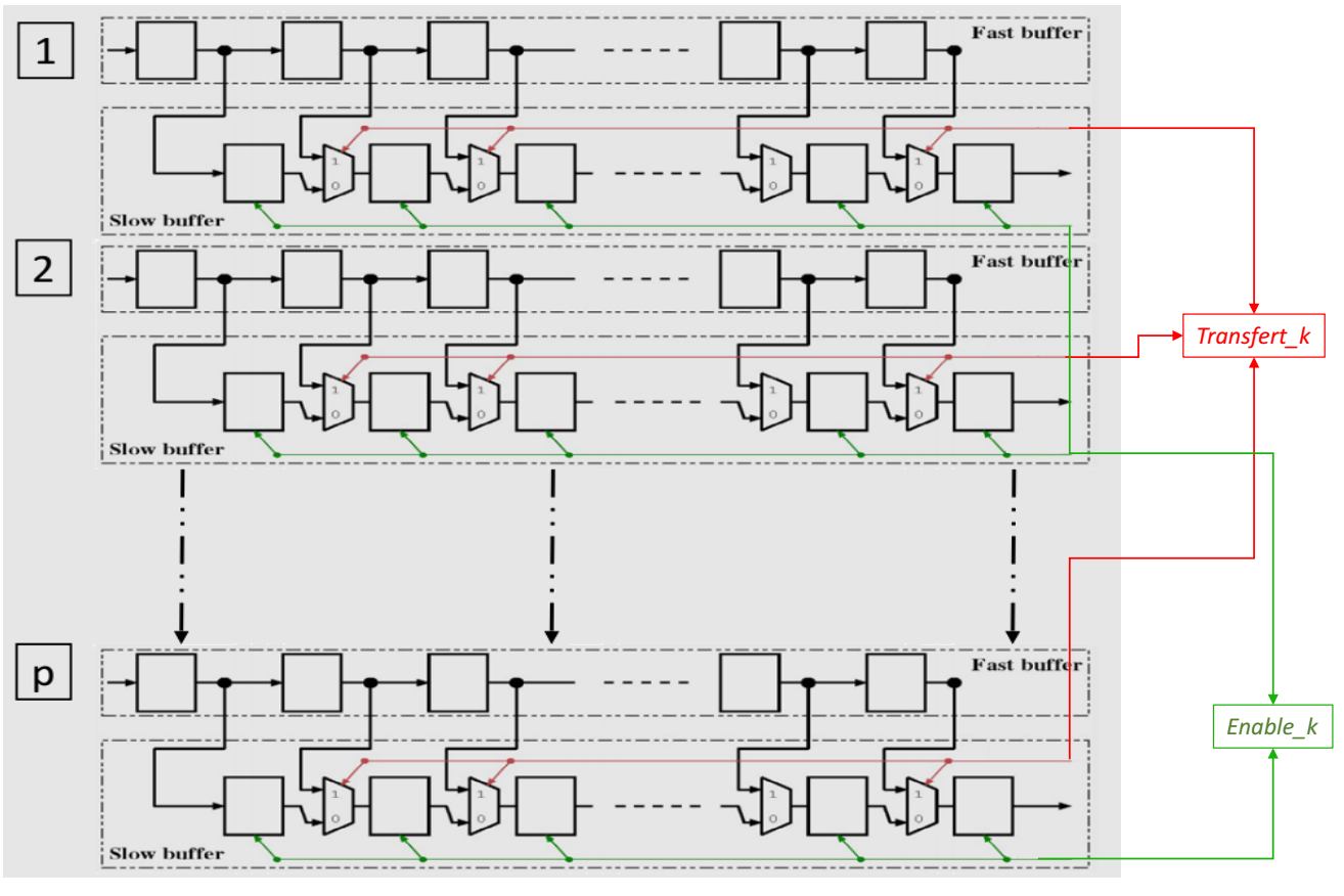 Figure 7. Structure of the DWPT buffer block in stage k
The is dedicated to generate and manage the various controls signals and related to stage .
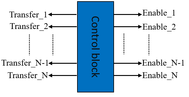 Figure 8. Control unit block
B. Synthesis results
As we mentioned, this architecture is fully configurable in synthesis by three parameters: the wavelet scale (the tree depth), the order of the filters and the filter coefficient quantization (generic parameters in the VHDL-RTL model). Moreover, it is partially configurable after synthesis of filters coefficient values corresponding to different wavelet family (with the same filter order). This means we can change the type of wavelet without re-synthesis our architecture (the coefficients are loaded dynamically after synthesis) where it was not the case for all the previous work.
The resources consumed by our proposed architecture resources are given as 2-tuples ( ): where stands for logic elements and for logic registers. The associated data processing rate of our proposed architecture depends on clock frequency (clock frequency obtained after synthesis is around 200 MHz with order quantization 5 and around 100 MHz with order quantization 16) and the number of input signals, which is given in Mega-samples in clock cycle during the synthesis.
In tables 1, 2 and 3, the configuration parameters are presented as 3-tuples: Depth of DWPT tree, Order of filter, and Quantization with the synthesis results of implementation for 4, 8 and 16 parallel DWPT architecture. Although the highest rate of our architecture is not requiring any memory or DSP blocks.
Table 1. Implementation results of 4-parallel DWPT architecture
| Design parameters
(Depth, Order Quantization) |
Data processing rate | Resources usage
( ) |
| (2, 2, 5) | 415.36 | (471,296) |
| (3, 2, 5) | 400.86 | (756,510) |
| (4, 2, 5) | 389.56 | (1204,899) |
| (2, 4, 5) | 403.52 | (879,456) |
| (3, 4, 5) | 342.46 | (1299,719) |
| (4, 4, 5) | 375.24 | (1941,1171) |
| (2, 16, 5) | 357.99 | (3299,1416) |
| (3, 16, 5) | 369.83 | (4794,1924) |
| (4, 16, 5) | 3425.69 | (6397,2614) |
| (2, 2, 16) | 208.14 | (2571,905) |
| (3, 2,16) | 198.62 | (4216,1599) |
| (4, 2,16) | 209.89 | (5850,2853) |
| (2, 4,16) | 201.18 | (5038,1324) |
| (3, 4,16) | 194.60 | (7521,2260) |
| (4, 4,16) | 184.120 | (10374,3636) |
| (2, 16,16) | 180.41 | (4902,4402) |
| (3, 16,16) | 220.31 | (6805,5729) |
| (4, 16,16) | 213.63 | (9107,7752) |
Table 2. Implementation results of 8-parallel DWPT architecture
| Design parameters
(Depth, Order Quantization) |
Data processing rate | Resources usage
( ) |
| (2, 2, 5) | 583.03 | (1109,504) |
| (3, 2, 5) | 557.23 | (1699,935) |
| (4, 2, 5) | 562.25 | (2754,1531) |
| (2, 4, 5) | 586.20 | (2120,897) |
| (3, 4, 5) | 506.77 | (3050,1197) |
| (4, 4, 5) | 526.91 | (4603,2023) |
| (2, 16, 5) | 499.48 | (7689,2447) |
| (3, 16, 5) | 504.56 | (12176,3166) |
| (4, 16, 5) | 478.26 | (14956,4571) |
| (2, 2, 16) | 282.35 | (6079,1696) |
| (3, 2,16) | 294.41 | (9279,2735) |
| (4, 2,16) | 300.60 | (13489,5011) |
| (2, 4,16) | 289.86 | (12032,2582) |
| (3, 4,16) | 273.15 | (17549,3965) |
| (4, 4,16) | 238.45 | (24311,6363) |
| (2, 16,16) | 302.62 | (11263,7856) |
| (3, 16,16) | 325.85 | (14750,11451) |
| (4, 16,16) | 309.31 | (21314,13091) |
3.2. Second proposed architecture: Parallel-Pipeline architecture of IDWPT with sharing resources
A new P-parallel architecture of IDWPT will proposed in the following part, which can provide ultra-high speed data processing and low cost resources consummation.
Table 3. Implementation results of 16-parallel DWPT architecture
| Design parameters
(Depth, Order Quantization) |
Data processing rate | Resources usage
( ) |
| (2, 2, 5) | 718.13 | (3668, 652) |
| (3, 2, 5) | 710.42 | (6019, 960) |
| (4, 2, 5) | 709.04 | (8655, 1243) |
| (2, 4, 5) | 536.55 | (5991, 1689) |
| (3, 4, 5) | 517.53 | (8380, 2363) |
| (4, 4, 5) | 516.33 | (11181, 2601) |
| (2, 16, 5) | 464.04 | (30012, 4881) |
| (3, 16, 5) | 454.15 | (37172, 6575) |
| (4, 16, 5) | 454.92 | (38374, 7680) |
| (2, 2, 16) | 455.49 | (11116, 3395) |
| (3, 2,16) | 447.30 | (17679, 4330) |
| (4, 2,16) | 446.25 | (25389, 4830) |
| (2, 4,16) | 336.75 | (31336, 5137) |
| (3, 4,16) | 331.99 | (39361, 7764) |
| (4, 4,16) | 341.59 | (42687, 10342) |
| (2, 16,16) | 302.46 | (26408, 15572) |
| (3, 16,16) | 303.44 | (33859, 20959) |
| (4, 16,16) | 298.79 | (36348, 24456) |
The reconstruction process of the P-parallel IDWPT architecture is simply the reversed form of P-parallel DWPT. Considering the diagram in Figure 4, we can observe that any filter of level is able to process times the amount of data to be processed on level 1. Thus, the total amount of data by all filters to be processed in level k is the same as in level 1 ( ). It is the same remark that is observed at the DWPT in the previous part (III.1 a). Moreover, we can notice that at any filter, in a given level, half the data is processed than its neighbors on the output side, and twice its neighbor on the input side. This implies that the construction of structure tree have repeated functionally blocks and the complexity of the filters is the same for all stages.
To eliminate the exponential evolution of filters number as function of depth order, we linearize and serialize the filtered data in different stages. Consequently, instead of using low pass filters and low pass filters to filter data in stage , we just implement only one modified filter in each stage. As shown in figure 10, the number of used modified transposed FIR filter bank increases linearly a function of depth order.
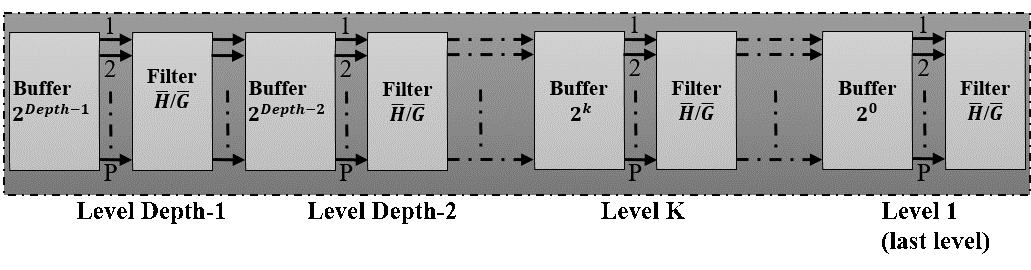 Figure 10. Data path diagram of the proposed P-parallel IDWPT architecture
The modified single filter ( Filter Block) can process the same amount of data on stage in the original tree (Figure 4). In figure 10, is the high-pass filter and low-pass filter, which are related to and , in equation (16).
The structure for the modified FIR filter is the same as that presented in figure 5. The only difference is the coefficients of FIR filters concerning and . This filter provides the same functionality of that presented by Mallat in their binary tree, we also reduce their occupied area by merging low-pass and high-pass reconstruction filters function in the structure in a single block. The processing of filtering is similar to that used in decomposition part (sub section III-1) where we take a sample for filter and for filter by an alternatively process (on consecutive cycles) and so on.
Consequently, this modified block can process one sample in two clock cycles. To ensure the best interleaving and managing of data in different stages, we developed a key block in our entire model that is the “Buffer Block”, which is situated between the filters in different levels.
A. Buffer Block structure of IDWPT
The most important thing in our P-parallel IDWPT (Figure 10) is, as previously, the link between neighbor levels, which does not need any reorganize of data set. We use the same concept of buffer blocks as illustrated in Figure 6, so the size of the buffer shown in figure 11 depends on the stage in which it is implemented. The buffer block is then built up on two sub-blocks in each positions ( is an indicator of the stage where the block buffer is implemented).
Then in each level k in figure 10, the buffer block is built up on two types of shift register ( positions shift for each one): a “fast shift buffer” takes data from the previous stage, and a “slow shift buffer” which feeds its data from its own stage filter. Overall, the buffer size depends on the parallel degree and the stage in which it is implemented.
The fast shift buffer is faster than slow shift buffer where it achieves P-shift on each clock cycle while the “slow shift buffer” achieves P-shift on two-clock cycles. To handle this latency, we used an enable signal called which manages the slower shift rate in level . To control the transfer data from the fast buffer to slow buffer, we insert a counter signal to activate the signal on every cycles. This transfer operation is performed P times at each stage.
The synthesis results of implementation of our P-parallel IDWPT architecture based on modified P-parallel FIR filter structure will be the subject of this part.
This architecture of P-parallel IDWPT is fully configurable in synthesis by three parameters: the wavelet scale (the tree depth), the order of the filters and the filter coefficient quantization (generic parameters in the VHDL-RTL model). Moreover, it is partially configurable after synthesis of filters coefficients values corresponding to different wavelet families (which have the same filter order). The resources consumed by our proposed architecture resources are given as 2-tuples ( ): where stands for logic elements and for logic registers. To generate the differences counter, the different control signals and related to stage , we proposed also like in figure 8 a block control unit.
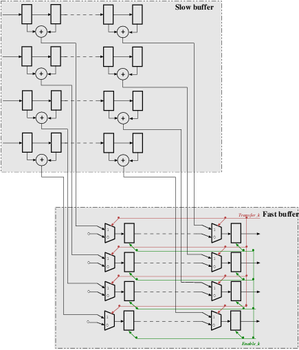 Figure 11. Structure of the IDWPT buffer block in stage k with degree of parallelization P=4
Table 4. Implementation results of 4-parallel IDWPT architecture
| Design parameters
(Depth, Order Quantization) |
Clock
frequency |
Resources usage
( ) |
| (2, 2, 5) | 205 | (109, 186) |
| (3, 2, 5) | 201.82 | (166,312) |
| (4, 2, 5) | 196.16 | (244,505) |
| (2, 4, 5) | 152.88 | (265,286) |
| (3, 4, 5) | 152.58 | (379,442) |
| (4, 4, 5) | 153.37 | (483,665) |
| (2, 16, 5) | 144.03 | (1447,886) |
| (3, 16, 5) | 137.44 | (1983,1222) |
| (4, 16, 5) | 136.24 | (2457,1625) |
| (2, 2, 16) | 132.36 | (578,582) |
| (3, 2,16) | 135.34 | (833,972) |
| (4, 2,16) | 133.69 | (1102,1572) |
| (2, 4,16) | 104.57 | (1594,902) |
| (3, 4,16) | 102.77 | (2174,1388) |
| (4, 4,16) | 100.61 | (2772,2084) |
| (2, 16,16) | 94.14 | (7719,2822) |
| (3, 16,16) | 92.08 | (10557,3884) |
| (4, 16,16) | 90.49 | (13469,5156) |
B. Synthesis results
In tables 4, 5 and 6, the configuration parameters are presented as 3-tuples: Depth of DWPT tree, Order of filter, and Quantization with the synthesis results of implementation for 4, 8 and 16 parallel DWPT architecture. Although the highest rate of our architecture does not require memory or DSP blocks.
3.1. Third proposed architecture: Parallel-Pipeline architecture of IDWPT-DWPT with sharing resources and shared FIR modified filter
This part is dedicated to present another version of parallel DWPT/IDWPT architecture. In some applications and especially in digital communication, we find that there is a need to implement the DWPT and IDWPT transforms on the same FPGA split. Certainly, we can implement our architecture (P-parallel DWPT and P-parallel IDWPT) on the same board to ensure the transformation functionality using the same constraints of work with ultra-high throughput and low resources consumption (consequently low power consumption). We notice a big regularity in the architecture of P-parallel DWPT (Figure 6) and P-parallel IDWPT (Figure 10), particularly in the modified FIR filters on the different levels where the structure of modified FIR filter is the
Table 5. Implementation results of 8-parallel IDWPT architecture
| Design parameters
(Depth, Order Quantization) |
Clock
frequency |
Resources usage
( ) |
| (2, 2, 5) | 207.04 | (202, 347) |
| (3, 2, 5) | 195.77 | (301,574) |
| (4, 2, 5) | 198.73 | (409,863) |
| (2, 4, 5) | 147.15 | (527,527) |
| (3, 4, 5) | 148.39 | (705,804) |
| (4, 4, 5) | 147.65 | (813,1123) |
| (2, 16, 5) | 136.44 | (2955,1607) |
| (3, 16, 5) | 133.05 | (3802,2184) |
| (4, 16, 5) | 131.56 | (4288,2683) |
| (2, 2, 16) | 128.75 | (1140,1095) |
| (3, 2,16) | 123.08 | (1529,1806) |
| (4, 2,16) | 128.04 | (1828,2711) |
| (2, 4,16) | 99.98 | (3098,1671) |
| (3, 4,16) | 98.87 | (4094,2542) |
| (4, 4,16) | 98.95 | (4733,3543) |
| (2, 16,16) | 90.16 | (15416,5127) |
| (3, 16,16) | 86.02 | (20279,6958) |
| (4, 16,16) | 86.1 | (23194,8535) |
Table 6. Implementation results of 16-parallel IDWPT architecture
| Design parameters
(Depth, Order Quantization) |
Clock
frequency |
Resources usage
( ) |
| (2, 2, 5) | 197.47 | (389,668) |
| (3, 2, 5) | 195.35 | (573,1096) |
| (4, 2, 5) | 194.97 | (742,1576) |
| (2, 4, 5) | 147.54 | (1091,1008) |
| (3, 4, 5) | 142.31 | (1410,1526) |
| (4, 4, 5) | 141.98 | (1552,2036) |
| (2, 16, 5) | 127.6 | (5894,3048) |
| (3, 16, 5) | 124.88 | (7300,4106) |
| (4, 16, 5) | 125.09 | (7536,4796) |
| (2, 2, 16) | 125.25 | (2183,2120) |
| (3, 2,16) | 123.02 | (2704,3472) |
| (4, 2,16) | 122.71 | (3016,4986) |
| (2, 4,16) | 92.6 | (6154,3208) |
| (3, 4,16) | 91.29 | (7730,4848) |
| (4, 4,16) | 93.93 | (8383,6458) |
| (2, 16,16) | 83.17 | (30619,9736) |
| (3, 16,16) | 83.44 | (39257,13104) |
| (4, 16,16) | 82.16 | (42143,15290) |
same and the difference is particularly in the loaded coefficients after synthesis. We think to develop, at last but not at least, new architecture, which retains all features from previous architectures (ultra-high throughput, generic, configurable with depth and with order of filters and with quantization). In addition, the same architecture can be implemented with P-parallel DWPT or P-parallel DWPT by the selection of the active way as shown in figure 12.
In this scheme, we represent a new pipeline-parallel architecture of DWPT/IDWPT with shared P-parallel FIR filter. Furthermore, instead of the implementation of 2*Depth P-parallel FIR filter in this architecture, we used the half of hardware architecture with the conservation of the ultra-throughput rate.
The buffers block are similarly presented in previous part in P-parallel DWPT and P-parallel IDWPT. Respectively, Mux_Data and DeMux_Data blocks are implemented to manage data between the buffers and the shared P-parallel FIR filter in P-parallel DWPT or P-parallel IDWPT. The Mux_Filter blocks are multiplexer, used to precise the transform direction and to manage the loading FIR filters coefficients after synthesis.
A. Synthesis results
To evaluate the performance of our P parallel DWPT/IDWPT architecture, we just implement the Blocks of P-parallel FIR filters, which gives us a percentage of the resources quantity consumption that have been dispensed by using a shared P-parallel FIR filters.
The compilation results of area consumption for different values of the configuration parameters, that mean tree depth, filter order, coefficient quantization (in number of bits), and parallel degree are presented in table 7 with different parallel degree.
Table 7. Implementation results of 4, 8 and 16-parallel degree of Parallel FIR architecture
| Design parameters
(Depth, Order Quantization) |
FIR Resources usage
( ) |
||
| P=4 | P=8 | P=16 | |
| (2, 2, 5) | (41,27) | (128,64) | (298,106) |
| (3, 2, 5) | (41,28) | (138,67) | (315,110) |
| (4, 2, 5) | (49,30) | (138,70) | (315,113) |
| (2, 4, 5) | (53,37) | (148,83) | (371,127) |
| (3, 4, 5) | (53,38) | (167,86) | (371,131) |
| (4, 4, 5) | (61,40) | (167,89) | (371,135) |
| (2, 16, 5) | (112,94) | (281,189) | (701,319) |
| (3, 16, 5) | (112,96) | (298,195) | (701,322) |
| (4, 16, 5) | (119,98) | (307,195) | (701,327) |
| (2, 2, 16) | (198,83) | (302,107) | (368,161) |
| (3, 2,16) | (198,88) | (328,112) | (368,166) |
| (4, 2,16) | (218,93) | (353,117) | (368,172) |
| (2, 4,16) | (257,114) | (378,138) | (431,337) |
| (3, 4,16) | (257,119) | (428,143) | (431,198) |
| (4, 4,16) | (297,124) | (428,148) | (431,203) |
| (2, 16,16) | (557,278) | (760,314) | (1164,408) |
| (3, 16,16) | (557,283) | (806,319) | (1164,408) |
| (4, 16,16) | (593,288) | (806,324) | (1164,413) |
From table 7, we notice that the resources consumption are the same with the same order filter (which is expected). Moreover, with half usage of P-parallel FIR filter in P-parallel DWPT/IDWPT, we gain resources percentage from 3 to 5 % for a depth = 4 and filter order = 16, which is significant especially with the large depth and high filter order (like discrete Meyer wavelet).
This is a very important result because classically it is too difficult to implement in the same board simultaneously both parallel architectures.
4. Comparison
To evaluate the performance of each architecture, we make a comparison chart (Table 8) with several DWPT and IDWPT architectures designs achieved in literature.
A quantitative and comprehensive comparative are presented in Table 8, where we can observe that:
- Our architectures are implemented without using any memory or DSP block where most of other architecture required that.
- Our models DWPT/IDWPT architectures are generic and fully configurable. They are suitable for all wavelet families (where the wavelet families are simplified by the filters orders) where it is not the case for all previous works.
- In our architectures; the quantization, the depth order and the filters order are theoretically unlimited (depends on the limit of manufacturing technology)
From these observations, table 8 presents the superiority of our architectures that are clearly presented on the high bite-rate driven by high frequency (around 200MHz).
5. Conclusion
In this work, we have proposed three powerful P-parallel/pipeline configurable architecture of Direct Discrete Wavelet Packet Transform (DWPT) and Inverse Discrete Wavelet Packet Transform (IDWPT) based on Mallat binary tree using bank filter concept, which provide high throughput with minimal hardware resources. The considered problem is to accelerate data processing in clock cycle and decrease the total hardware resources used.
To solve these problems, we develop a P-Parallel modified FIR filter based on transposed FIR filters that can share hardware resources between low-pass and high-pass filters (by merging their functionality). The effective data path maintains a short critical path allowing high operation frequency to be reached, where synthesis results indicate that our architecture provides a very high speed data processing with minimum resources. For example: for a parallel degree P=16, depth order = 2, filter order = 2 and order quantization = 5 we reach a very high bit rate equal to 3159.52 Mega samples. We also developed a new effective architecture for both DWPT and IDWPT implemented in the same programmable board, conserving the high throughput performance with more decreased hardware resources consumption.
Those proposed architectures (IDWPT and DWPT) are fully configurable at synthesis as function of P-parallel degree, depth (number of tree stages), filter order and filter coefficient quantization (generic parameters in the VHDL-RTL model). Furthermore, they are re-configurable after synthesis by loading the filter coefficients, which depend on different wavelet family during operations (after synthesis) that providing high flexibility of DWPT/IDWPT transforms.
Perspectives
In this work, we present a different parallel version of hardware implementation in FPGA of DWPT/IDWPT. This work is still in progress where we are constructing another generation of DWPT/IDWPT implementation, which can provide more performance and can be used in new application domains.
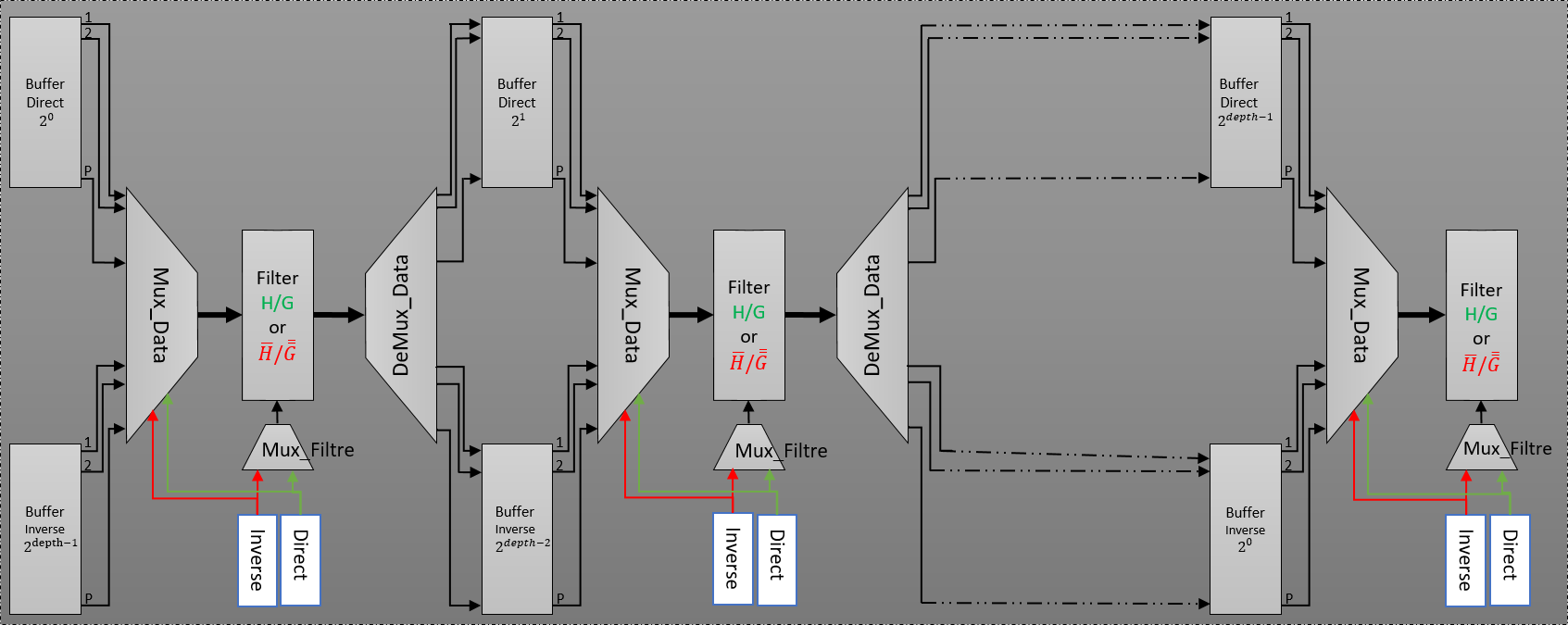 Figure 12. Proposed data-path diagram of both P-parallel DWPT and IDWPT architecture.
Table 8. Comparison of proposed architectures with existing DWPT and IDWPT architectures.
| Tze-Yun et al.[28] | Marino et al.
[29] |
Mohanty et al. [30] | Madishetty et al. [23] | Wang et al.
[27] |
Wu et al. [12] | Meihua et al. [21] | Proposed architecture N°1 | Proposed architecture N°2 | Proposed architecture N°3 | |
| Wavelet | Daub-4 | Quadri-filter | Daub-4 | Daub-6 | Lifting- Db4 | Quadri-filter | Quadri-filter | arbitrary | arbitrary | arbitrary |
| DWPT/ IDWPT | Both | DWPT | DWPT | DWPT | Both | Both | DWPT | DWPT | IDWPT | Both |
|
Logic cell |
N/A | N/A | 426 | 1040 | N/A | 30192 (logic gate) | 1835 (logic unit) | 3668 (logic element) | 389 (logic element) | |
|
Technology |
Xilinx
XC2V4000 |
N/A | CMOS 90nm | Xilinx Virtex 6 | CMOS
180 nm |
0.35 µm | Altera EP20K200E | Altera Cyclone IV | Altera Cyclone V | Altera Cyclone V |
| Max. Freq.(Mhz)/
Bitrate |
N/A | N/A | 20 | 306.15 | 20 | 100 | 29 | Bitrate:718.13 | Feq.: 197.47 | 200 |
| Memory | Yes | N/A | yes | yes | Yes | N/A | yes | No | No | No |
|
Quantization (bits) |
N/A | N/A | N/A | N/A | 32 | N/A | Test with 5 to 16 (up tounlimitedtheatrically) |
Test with 5 to 16 (up tounlimitedtheatrically) |
Test with 5 to 16 (up tounlimitedtheatrically) |
|
| DSP | N/A | N/A | N/A | N/A | N/A | No | No | No | ||
| Depth | 3 | N/A | N/A | 4 | 3 | 3 (up to 6) | 3 | 2, 3 and 4 (up to
unlimited theatrically) |
2, 3 and 4 (up to
unlimited theatrically) |
2, 3 and 4 (up to
unlimited theatrically) |
| Parallel degree | 4,8 and 16 (up to
unlimited theatrically) |
4,8 and 16 (up to
unlimited theatrically) |
4,8 and 16 (up to
unlimited theatrically) |
- S. Mallat, A wavelet tour of signal processing, Academic Press, 1999.
- R. Dilmaghani and M. Ghavami, “Comparison between wavelet-based and Fourier-based multicarrier UWB systems,” IET Communications, Vol. 2, Issue 2, Feb. 2008. http://dx.doi.org/10.1049/iet-com:20070181
- A. Grossmann and J. Morlet, “Decomposition of Hardy functions into square integrable wavelets of constant shape,” SIAM journal on mathematical analysis, 15(4), 723-736, 1984. https://doi.org/10.1137/0515056
- S. Mallat, “Multiresolution approximations and wavelet orthonormal bases of L2(R),” Transactions of the American Mathematical Society, vol. 315, no. 1, pp. 69–87, 1989. https://doi.org/10.1090/S0002-9947-1989-1008470-5
- Y. Meyer, “Wavelets and operators,” vol. 37 of Cambridge Studies in Advanced Mathematics. Cambridge University Press, 1992.
- C.K. Chui, “An Introduction to Wavelets,” Philadelphia, SIAM, vol. 38, 1992.
- I. Daubechies, Ten lectures on wavelets, Philadelphia, SIAM, vol. 61, pp. 198–202, 1992.
- T.C. Denk and K.K. Parhi, “Architectures for lattice structure based orthonormal discrete wavelet transforms,” IEEE International Conference on Application Specific Array Processors, pp. 259-270, Aug. 1994. https://doi.org/10.1109/ASAP.1994.331798
- H. H. A. Hatem, M. El-Matbouly, N. Hamdy, K. A. Shehata, “VLSI architecture of QMF for DWT integrated system,” Circuits and Systems, MWSCAS 2001. Proceedings of the 44th IEEE 2001 Midwest Symposium on (Volume: 2), pp. 560–563, 2001. https://doi.org/10.1109/MWSCAS.2001.986253
- G. Strang and T. Nguyen, Wavelets and Filter Banks, Wellesley-Cambridge Press, 1997.
- W. Xiaodong, L. Yongming and C. Hongyi, “Programmable wavelet packet transform processor,” In Electronics Letters, vol. 35, no. 6, pp. 449-450, 18 Mar 1999. https://doi.org/10.1049/el:19990330
- B-F. Wu and Y-Q. Hu, “An efficient VLSI implementation of the discrete wavelet transform using embedded instruction codes for symmetric filters,” IEEE Transactions on Circuits and Systems for Video Technology, vol. 13, no. 9, pp. 936–943, September 2003. https://doi.org/10.1109/TCSVT.2003.816509
- G. Paya, M. M. Peiro, F. J. Ballester, V. Herrero and J. Cerda, “A new inverse architecture discrete wavelet packet transform architecture,” IEEE, Signal Processing and Its Applications, 7803-7946, 443 – 446 vol.2, 2003. https://doi.org/10.1109/ISSPA.2003.1224909
- A. Jamin and P. Mähönen, “FPGA implementation of the wavelet packet transform for high speed communications,” International Conference on Field Programmable Logic and Applications. Springer Berlin Heidelberg, 2002. https://doi.org/10.1007/3-540-46117-5_23
- M. Trenas, J. López, M. Sanchez, F. Argüello and E. L. Zapata, “Architecture for Wavelet Pack et Transform with Best Tree Searching,” In Application-Specific Systems, Architectures, and Processors, 2000. Proceedings. IEEE International Conference on (pp. 289-298). IEEE, 2000. https://doi.org/10.1109/ASAP.2000.862399
- M. Trenas, J. López and E. Zapata, “FPGA Implementation of Wavelet Packet transform with Reconfigurable Tree Structure,” Euro micro Conference, 2000. Proceedings of the 26th Volume 1, 5-7, pp. 244 – 251 vol.1, September 2000. https://doi.org/10.1109/EURMIC.2000.874639
- M. Trenas, J. López, E. Zapata and F. Argüello, “A Configurable Architecture for the Wavelet Packet Transform,” Journal of VLSI signal processing systems for signal, image and video technology, Volume 32, Issue 3, pp 255-273, November 2002. https://doi.org/10.1023/A:1020221003822
- M. Farahani and M. Eshghi, “Architecture of a wavelet packet transform using parallel filters,” TENCON 2006 – IEEE Region 10 Conference, p. 7-10, 2006. https://doi.org/10.1109/TENCON.2006.343965
- M. Farahani and M. Eshghi, “Implementing a new architecture of wavelet packet transform on FPGA,” Proceedings of the 8th WSEAS International Conference on Acoustics & Music: Theory & Applications, Vancouver, Canada. 2007.
- M.A. Farahani, S. Mirzaei and H.A. Farahani, “Implementation of a reconfigurable architecture of discrete wavelet packet transform with three types of multipliers on FPGA,” 24th IEEE Canadian Conference on Electrical and Computer Engineering (CCECE), 2011. https://doi.org/10.1109/CCECE.2011.6030704
- X. Mei-hua, C. Zhang-jin, R. Feng, and C. Yu-lan, “Architecture research and VLSI implementation for discrete wavelet packet transform,” High Density Microsystem Design and Packaging and Component Failure Analysis, 2006. HDP’06. Conference on. IEEE, 2006. https://doi.org/10.1109/HDP.2006.1707554
- D. Garcia, M. Mansour and M. Ali, “A flexible hardware architecture for wavelet packet transform with arbitrary tree structure,” IEEE Transactions on circuits and systems – II: Express briefs, vol. 60, no. 10, p. 657-661, October 2013. https://doi.org/10.1109/TCSII.2013.2277964
- S. K. Madishetty, A. Madanayake, R. J. Cintra and V. S. Dimitrov, “Precise VLSI Architecture for AI Based 1-D/ 2-D Daub-6 Wavelet Filter Banks with Low Adder-Count,” IEEE Transactions on circuits and systems-I: regular paper, Vol. 61, No. 7, 1984 – 1993, July2014. https://doi.org/10.1109/TCSI.2014.2298283
- M. Chehaitly, M. Tabaa, F. Monteiro and A. Dandache, “A fast and configurable architecture for Discrete Wavelet Packet Transform,” In Design of Circuits and Integrated Systems (DCIS), 2015 Conference on (pp. 1-6), 2015. https://doi.org/10.1109/DCIS.2015.7388599
- M. Chehaitly, M. Tabaa, F. Monteiro and A. Dandache, “A VHDL-RTL implementation for a fast and configurable design of inverse discrete wavelet packet transform,” Design of Circuits and Integrated Systems (DCIS), 2016 Conference on, p. 1 – 5, 2016.
- M. Antonini, M. Barlaud, P. Mathieu and I. Daubechies, “Image coding using wavelet transform,” IEEE Transactions on image processing, 1(2), 205-220, 1992.
- C. Wang, J. Zhou,L. Liao, J. Lan, J. Luo, X. Liu and M. Je, “Near-threshold energy-and area-efficient reconfigurable DWPT/DWT processor for healthcare – monitoring Applications,” IEEE Transactions on Circuits and Systems II: Express Briefs, 62(1), 70-74, 2015. https://doi.org/10.1109/TCSII.2014.2362791
- T.-Y. Sung, H.-C. Hsin, Y.-S. Shieh and C.-W. Yu, “Low-power multiplierless 2-D DWT and IDWT architectures using 4-tap Daubechies filters,” In Proc. Seventh Int. Conf. PDCAT, pp. 185–190, 2006. https://doi.org/10.1109/PDCAT.2006.78
- F. Marino, “Two fast architectures for the direct 2-D discrete wavelet transform,” IEEE Trans. Signal Process, vol. 49, no. 6, pp. 1248–1259, 2001. https://doi.org/10.1109/78.923307
- B. K. Mohanty and P. K. Meher, “Memory-efficient high-speed convolution-based generic structure for multilevel 2-D DWT,” IEEE Trans. Circuits Syst. Video Technol., vol. 23, pp. 353–363, 2013. https://doi.org/10.1109/TCSVT.2012.2203745