A Machine Learning Framework Using Distinctive Feature Extraction for Hand Gesture Recognition

Adv. Sci. Technol. Eng. Syst. J. 3(5), 72–81 (2018);
 DOI: 10.25046/aj030510
There are more than 7billion people in the world where there are around 500 million people in the world who are denied from normal lifestyle due to physical and mental issue. It is completely fair to say that every person deserves to enjoy a normal lifestyle. While physically and mentally challenged people find suitable way to surpass their limits, thus become able in other ways, researchers always try to find solutions better than the existing one. A complete remedial of such issue is included in advanced medical science, and the amelioration of such issue to a better extent is the challenge for the engineers. In this work we have focused on hand gestures. Hand gestures are created using the movement of hand and arm, using fingers to create different shapes, using fingers and palm to create different angles. Single or both hands can be used to create different expressions. The main objective of this work is to generate an algorithm that can recognize different patterns of hand gestures with notable accuracy. American Sign Language is one possible reference model that can be used. Images of different hand signs are taken as inputs using a webcam, followed by segmentation of the images using polygon approximation and approximate convex decomposition. Feature extraction is done by recording the unique feature among the various convex segments of the hand. The resultant singularities are then used as extracted feature vectors. This involves training with the obtained features which are approximately unique for different hand gestures. Hence, we will be able to identify sign languages and successively make disabled individuals socially acceptable. This work is an extension of the work entitled “A Machine Learning Framework Using Distinctive Feature Extraction for Hand Gesture Recognition” in 2018 IEEE 8th Annual Computing and Communication Workshop and Conference (IEEE-CCWC).
1. Introduction
Gesture Technology is an emerging scope in the field of Computer Science, precisely machine learning. The objective of gesture technology is to interpret or recover the human gesture using intelligent machines. Complex mathematical algorithm is used to interpret the gestures. Fundamentally spoken, the mathematical algorithms contain a large set of test and training data, which are eventually used to compare with the current status of the human, thus come out with an appropriate result that can describe the gesture. Gesture is vastly used in human-machine interaction where the machine detects gesture input from the human and responds accordingly. Advanced technology has created a possible way for communication between 2 or more machines, with no human presence, using gesture input and output. Furthermore, gesture technology can be very useful in human to human interaction, precisely where the persons involved in the communication do not have the same mode of communication. While other body parts are also used in gesture technology, the most used parts are face and hands. In general term, gesture can be divided into 2 types- a) body gesture: where body is used to create expression; and b) hand gesture: where only hand is used to create expression. A sign or symbol is the most commonly used hand gesture [1]. Gesture can be further distinguished on basis of static gesture [2] and dynamic gesture [3]. Face images in gesture technology are mostly used for emotion detection [4] and as a security tool used in gadgets and other devices [5]. Some main application areas for gesture technology include gaming sector, home automation, automotive sector, sign language interpretation. In hand gesture technology, human can interact with machine or with another human through a machine that recognizes the hand gestures created by the human being [6]. Generally still images of hand gestures are sent as inputs to the machines, but there are also machines that can collect gesture data from live video footage. Thanks to advanced technology, touching of the machine is not necessary anymore; strong sensors in the machine can detect hand gestures from distance. Hand gesture technology is verily used in the later two of the previous example. In this domain, we will talk about hand gesture technology and sign language interpretation.
Enjoying the proper lifestyle is the birth right of every human being in this world. Everybody should be able to communicate and share expression with the outer world, but unfortunately not every time people are able to do so. It is always hard for people to communicate with others when mental or physical challenges become a barrier in the way. While it is safe to say that these people are verily able in other ways that help them to communicate, we always try to find a system better than the existing one. The most fundamental and most popular technique used in this field is creating sign language using hand gestures [7]. But the challenges occur when at least one of the people involved in such communications doesn’t know the sign language or how to create them. A few numbers of people who don’t need sign language for communication actually know this language, resulting in a great difficulty when there is a communication between 2 people where one of them only uses sign language for sharing expression. Based on practical experience, it is almost certain that these types of conversations do not proceed easily unless there is a third person who is used as an interpreter. There exist devices, as for example, data gloves, which are used to solve such problems during conversation. Data glove is an interactive device, basically a glove to wear with sensors on it. These sensors create precise capturing of hand gesture information. Though data glove is generally used in robotics, other application areas also include human interaction. This report refers only to camera based static hand gesture recognition [3]. Static hand gesture recognition technology has a useful application on communication between 2 persons where one is able to use a particular sign language (say ASL or American Sign Language) and other isn’t. A hand gesture recognition device is used as the protocol in this communication. As mentioned earlier, the device contains sensors to capture images and to detect gesture data and analyze them. The basic objective of the device is to eliminate the necessity of a third party interpreter, by allowing itself to do the same job. It captures gesture images as input and creates output suitable for non-ASL speaker. Generally the output is in textual format. The device is also used in the reverse situation, that is., taking textual or vocal words as inputs and creating sign language as outputs. Since the algorithms used in a device is based on a particular sign language, it is necessary that mode of communication from the sign language user’s side only includes one specific language, such as either Indian Sign Language (ISL)[8] or the American Sign Language (ASL)[9] but not an amalgam of both. The objective of this paper is to illustrate the extraction of unique features from each symbol or gesture in reference to an existing data set (ISL or ASL) and then train the machine with the obtained feature vectors using standard classification models.
Using a huge number of data in test set and training set creates less ambiguity for the machine while taking decision, and as a result it can give a more accurate output. As for example, a specific hand sign can be described by several textual words, and a set of hand signs can be described by 2 or more different sentences. The more there is data in the device’s memory based on previous trainings (that is, in training data set), the more accurately the device will be able to decode texts into proper sign languages. There are more necessities to be taken care of in order to get more accurate results. Use of white gloves is employed to eliminate unwanted wrinkles or groves on the palm and fingers. From the threshold image of the figure we obtain its minimum fitting polygon through what we call polygon approximation technique. The next step is Convex Decomposition technique. It segregates each of the convex parts of the hand, which is an essential step to identity the crucial aspects of the gesture. The next and final step is to extract the required unique features. The wrist point in the hand is considered to be the mid-point of the lowermost polygon.
The novelty of the proposed method is listed as follows.
- Extraction of individual features for each and every gesture creates the possibility of notable polarity and a chance of further efficient classification of the obtained
- The proposed method is equipped for large scale deployment through recognizing the demand and necessity of real time
- The produced results from trained dataset are favorable with adequate acceptance
2. Related Work
Both the Indian Sign Language (ISL) and American Sign Language (ASL) are comprised of a notable list of hand gestures, each with meaningful expression that can be used for any non-verbal communication. As mentioned earlier, the sign languages come real handy when we have the technology to decode a specific sign language to sounds/texts and vice-versa, thus useful in communication where one person is accustomed with sign language communication where as other person use vocal/ textual communication and does not know the sign language. In probability, Markov Model is a concept for modelling randomly changing system. According to this model, the next state of a random system mostly depends on the current state of the system; and not on the previous states. In 1960 William Stokoe developed a concept based on real time Markov-model based systems [10]. In this system, continuous American Sign Language (ASL) generates long combination of words as outputs. A single camera is used in this concept. The concept is still very much effective and is majorly used technique to recognize gestures. However, this implementation requires polygon approximation followed by convex decomposition.
The convex decomposition method is a special case of alternating sum of volumes (ASV) method. ASV can be defined as a series of convex elements stick together in a way such that for elements A, B, C, D, E, … the series will be: A u B / C u D / E and so on, where u is Union operation and / is Difference Operation [11]. In 1998, Starner proposed the using of convex hulls and set- difference operations [12]. A convergent convex decomposition is proposed that uses a combination of ASV decomposition and remedial partitioning for the non-convergence. The concept uses ASVP decomposition for image feature extraction, in other words, to identify the unique properties of an image that differentiates the image from others.
Polygon Approximation is very necessary in this context. The simplest idea of the process can be described by 4 steps – Identifying original shape (contour), chopping the shape around the corners, generate approximate convex lines for the chopped segments, merging the segments [13]. The decomposition of polygon with 0 or more holes into convex chops can be done approximately using Approximate Convex Decomposition (ACD) [14]. The algorithm used in this context is simple: iterative resolving of the most significant non-convex feature. Approximate Convex Decomposition method is applicable for both 2D and 3D models.
On the basis of simple cut and split paradigm of Chazelle, a method to compute a convex decomposition of a non-convex polyhedron of arbitrary genus (handles) and shells (internal voids) is generalized [15]. The algorithm is extended to work for a certain class of no manifold polyhedral.
A set of topological decimation operations to its dual graph is applied to calculate a hierarchical segmentation of mesh triangles, which is used for 3D mesh approximate convex decomposition [16]. The method of segmentation incudes a) portraying a triangle mesh and its corresponding dual graph, b) contracting of an arc of the dual graph, followed by the marking of the end-points of the two triangles corresponding to the dual arc’s as belonging to the same single cluster [17]. Segmentation can be of two types – direct segmentation and feature based segmentation. This particular model is important due to its adaptation to collision detection.
Inter-class variability enhancement and local-global ambiguity identification for each hand gesture is used in the automatic gesture recognition on Indian Sign Language (ISL) [18]. In ISL both hands can be used to represent an expression. Support Vector Machines (SVM) is used to classify each hand posture. In SVM data items are plotted as points in n-dimensional space, where n is the number of features. To classify dynamic gestures, Dynamic Time Warping (DTW) is used with the trajectory feature vector, and it achieves 86.3% recognition rate.
A pre-trained Google Net architecture representing a real-time sign language interpreter is described while developing the architecture with ILSVRC2012 dataset as training sets [19]. The idea is based on Convolution Neural Network (CNN). The main difference between Convolution Neural Network (CNN) and ordinary Neural Network is that CNN assumes that all the inputs are images, allowing researchers to encode certain properties into the architecture. The architecture is also trained with data sets from Surrey University and Massey University ASL data. This training set allows the architecture to apply transfer learning to this task. The system features a pipeline that captures video of signing a word as input through a designated application. Individual frames of the video are extracted and then they generate letter probabilities using a CNN.
Initially made use of Histogram of Oriented Gradients method extraction of feature, a feature extraction method uses two neural networks based recognition of 10 gestures [20]. The HOG [21] for an image describes the elementary property (such as color, shape and size) of an image. The objective of HOG method is object detection.
Data availability and analyzing their relative merits to determine features are essential for sign-language recognition (SLR) [22]. The objective is to continuous sign recognition and design a model that is independent of signer. The model should also be adapting to larger and noisy data sets. A statistical analysis based on four parameters: position, posture, orientation, and motion is used for a large vocabulary sign language interpreter with real-time continuous gesture recognition of sign language [23].
3. Data Set
The dataset for the proposed method has been centered on the popular and ubiquitous ASL (American Sign Language). It was formulated by the University of Surrey’s Center for Vision, Speech and Signal. The images referred have been indicated in the figure (1). We were able to gather approximately more than 500 colored images however the algorithm is constrained to static gesture recognition.
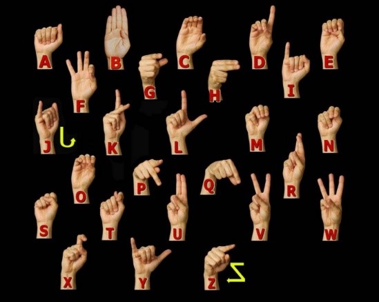 Figure 1: Different Gestures of ASL
4. Methodology
4.1. Pre-Processing
In the first step where we remove uneven parts of the image, dilate and erode and then generate a contour based on color edge detection. In the above set of figures, figure (2.a.I) is the initial figure, which is followed by figure (2.a.II) where we get the processed image. Using the processed image, we can find out the contour of the dark area using color edge detection technique [24] shown in the figure (2.a.III).
Once the contour is obtained then the rest of the area apart from the contour can be removed. We assumed that the hand will fit to (having minimal space between the hand and the frame border) the frame with the frame dimensions being constant. Once the background is removed, we need figure out the edges of the fingers and hands marked by black contrasting borders. Figure (2.a.IV) shows the finally obtained contour after preprocessing.
4.2. Approximation of Minimal Fitting Polygon
In digital image processing the approximation of arbitrary two-dimensional curves by polygonal figures is an imperative technique. In number applications, this technique is widely used for a purpose to represent lines and boundaries by means of polygons that have a minimum number of vertices so that fit condition is satisfied. Using island finding algorithm, we will be able to separate the fingers by inner smaller polygons.
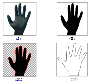 Figure 2 (a): Images Describing the Pre-Processing stage
To find the initial point we need to move by traversing alone the x-axis of the bottom frame and then we can find the first pixel that is colored black. The adjacent pixel can be located by a technique where we check the neighboring 8 pixels for a black pixel. The algorithm navigates through the contour of the figure from pixel to pixel, marking them based on their connectivity and the relative values of their neighbors. Connection between the pixels can be determined with the help of a 3×3 grid as shown in Figure (2.b). This grid can be either 4-connected or 8-connected.
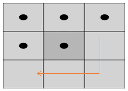 Figure 2 (b): 8 neighboring pixels of a pre-determined pixel
Now we need to find the 2D polygon by the following algorithm:
- Now take a black pixel at the starting point and continue moving along the pixel.
- Now joining the starting point pixel and adjacent point pixel (pivotal point) with a line to forms the base. Now we calculate the angle between the base and the next black point and store the calculated angle.
- Now if calculated angle is not considerably larger or smaller than the previously calculated angle, then we need to eliminate the current pixel point, and take the next pixel point lying in succession as the pivotal point. Else, if the angle is substantially more or less by a threshold value, then consider the current point and initialize the point as starting point. Go to step
- Repeat the above steps until we reach the initial point.
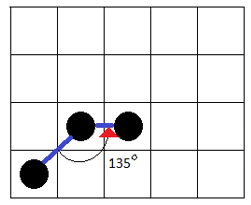 Figure 3 (a): Determining the Base Angles
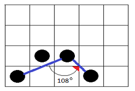 Figure 3 (b): Compare the recent angle with previously stored one. If the value is considerably similar (that is, not much greater or much smaller) to it, discard the pixel and move onto next pixel. Here the angle-135o is not considerably different from 108o hence discarded.
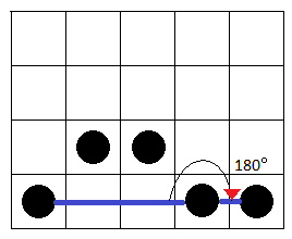 Figure 3 (c): Since 180o is considerably large, it is accepted
4.3. Island Finding Algorithm:
Here, we shall try to find out the minimal cyclic paths that enclose an area. A DFS traversal is done using the following constraints
- Stack(S) ß Push(R); S is the stack and R is root node.
- If S==null, end looping, else,
- If current node X present in Stack S, go to step 6.
- Else if X not present in Stack S and if it has child nodes then expand and explore child nodes if [Child(X)!=visited or Child(X)!=Parent(X)]. Else return to parent node.
- Repeat step 2.
- If substring[X, indexOfLastNode] or reverse (substring[X, indexOfLastNode]) is not already stored, then store (substring[X, indexOfLastNode] + X) as cyclic path Cn. Mark X as visited, POP(X) and PEEP(S). Go to step 5.
- If substring [X, indexOfLastNode] or reverse (substring [X, indexOfLastNode]) is already stored, then mark X as visited, POP(X) and PEEP(S). Go to step 5.
Once we find all the cyclic paths possible (C1, C2, C3….CN) then in a sequential order consider each cyclic paths, such that if elements of (Cn – lastElement) or elements of reverse (Cn – lastElement) is subset of Cm, then discard Cm. Continue until we have minimal unique cyclic paths possible. Then a given cyclic path forms either an island (finger or palm) or it’s the outer contour of the figure.
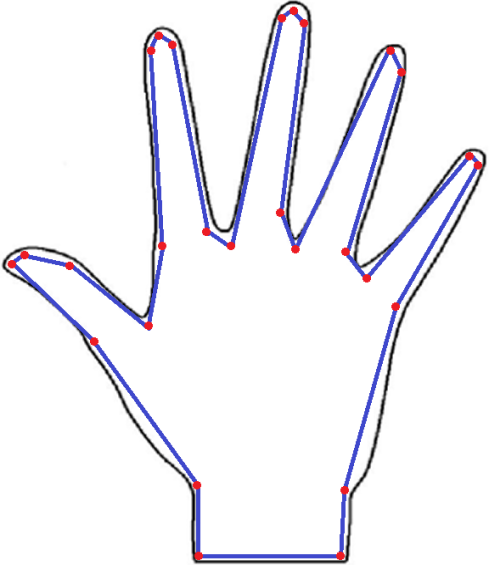 Figure 4: Illustration of Polygon Approximation of Polygon from the Shape of a Hand
In the above figure 4, the polygon with vertices of color red is sketched out from the curved outline of the image. A simple polygon P is formed when the vertices are joined by the blue lines.
The non-essential curves and bends are removed by the technique of approximation of minimal fitting polygon [25] and give us a figure that is bounded by line segments. The resultant image consists of a simple polygonal region in the plane bounded by a non-self-intersecting, closed, polygonal path. The polygonal path itself is part of the polygon; it is usually called the boundary.
4.4. Decomposition into Convex Components
Now if we partition the complex models into pieces it will be easy to deal with complex models or many-sided figure. Numerous difficulties can be solved more proficiently when the input is convex. Convex components Decomposition into results in pieces that are easy to process and additional approximation simples and eases computation, ensuring quicker and efficient output with manageable margins of inaccuracy.
Exact and approximate are two type of convex decomposition. Number of clusters in the model should be minimized so we do not use exact decomposition. We can get minimum number of clusters using Approximate convex decomposition ensuring that each cluster has a concavity lower that a predefined threshold.
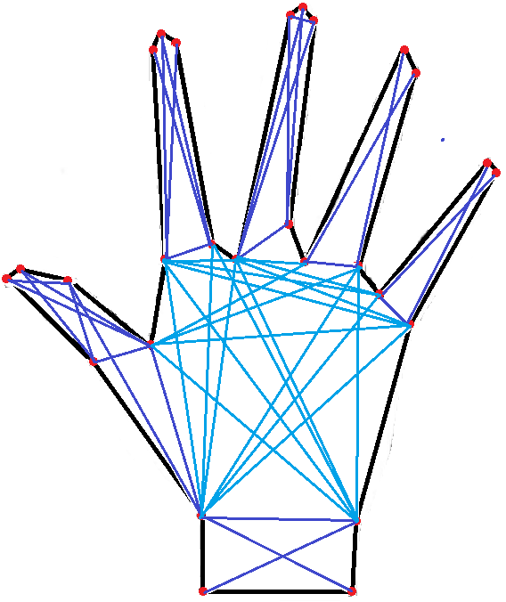 Figure 5: Polygon Decomposition into Non-Concave Sub graphs
The figure 5 given above shows the result of convex decomposition on the approximated polygonal segments obtained in the previous section.
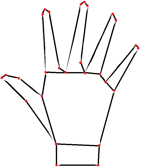 Figure 6: Resulting Convex Decomposition
In graph theory, where a complete subset of vertices of a graph G such that every two distinct vertices in the clique are adjacent is known as a clique. Subsequently, a maximum clique is one that has the largest possible number of vertices among other cliques. We then observe the maximum clique possible for any given point and then iteratively check for the points it connects. For given vertices V = {V1, V2, V3…VN},the we need to form two groups such that if VM V then, put VM into Checking array(C), and the vertices connecting VM in Pointing array(P). Put P’s last element into C and iteratively check if C elements has common connections with vertices in P. Group those points to find if they share any common point to find the approximate convex partition [26]. The maximum clique in the above mentioned visibility graph G, which is also undirected, is a complete sub graph of G having the maximum number of vertices.
4.5. Detecting Wrist Point and Reference Line
Deriving the data necessary for feature extraction the wrist point and the reference line are needed. The data are calculated with respect to the reference line. As the image is always considered to have the picture of the gesture in upright position so the wrist point is calculated as the mid-point of the bottom most polygon.
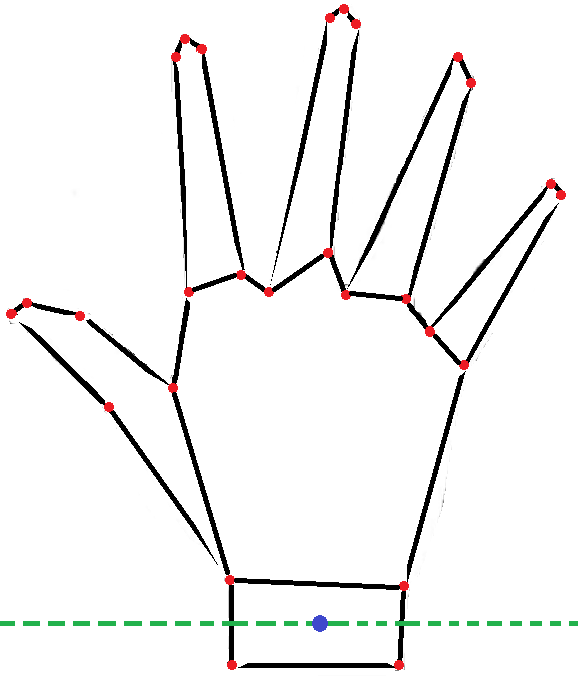 Figure 7: Deduction of Wrist Point and Reference Line
First identify the polygon associated with the wrist to derive the reference line. Then the mid-point of the polygon is calculated. The line that passes though the wrist point and is parallel to the bottom of the frame of reference is known as reference line. The green dotted line in figure 7 indicates the reference line. The bottom-most polygon is the polygon associated with the wrist, and the blue dot is the midpoint associated with the polygon.
4.6. Angle and Distance calculation with respect to Wrist Point
We now have the line of reference as well as the wrist point which are used to realize the different polygon segments in a given figure. To achieve this by observing the incrementing angles between each line joining the mid points of the polygonal segments and the line of reference. Our main objective here is to find unique feature vector to represent different hand gestures.
With reference to figure 8 by the convex decomposition process we begin by finding the mid-points of the segments. These points, marked as P1 through to P6, are then extended to join the wrist point marked as W. What is important to note here is that with each segment mid-point, the angle increases with the minimum being a possible 0° and the maximum being a possible 180°.This gradual expanding gap between the wrist point and each subsequent line signifies the change in finger positions and helps us to differentiate between them. Another aspect of the line joining the wrist point and the mid points of the segments is its length.
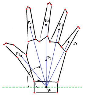 Figure 8: Connection of Wrist Point, described by P1, P2, with the Centroid (W) of the Decomposed Polygons
The property which helps us to decide whether a finger is in a folded or unfolded position is the distance between the wrist point and the mid-point of the corresponding polygonal segment of that finger. While the finger is in a folded position, the centroid of the segment gets located in a vertically lower level inside the polygon than it would if the finger was in an unfolded position. As a result, it becomes fairly easily distinguishable to recognize different signs, especially the ones that only differ by the positioning of a single finger.
Outcome of the above stated procedure produces the angle and distance of each mid-point of the different generated convex segments with respect to the reference line and wrist point. It shall be noted that the duality (angle and distance) needs to be converted to a singularity for feature extraction and forming a unique one-dimensional array representation of each distinguishable hand gesture.
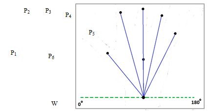 Figure 9: Unique Array of Data to Represent a Hand Gesture
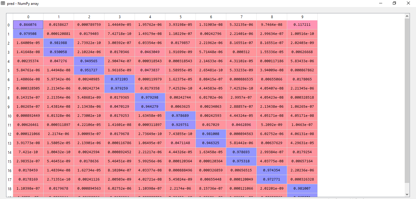 Figure 10 (a): Accuracy Calculation for 10 gestures with 20 images for test I.
 Figure 10 (b): Equivalent Confusion Matrix for Test-I
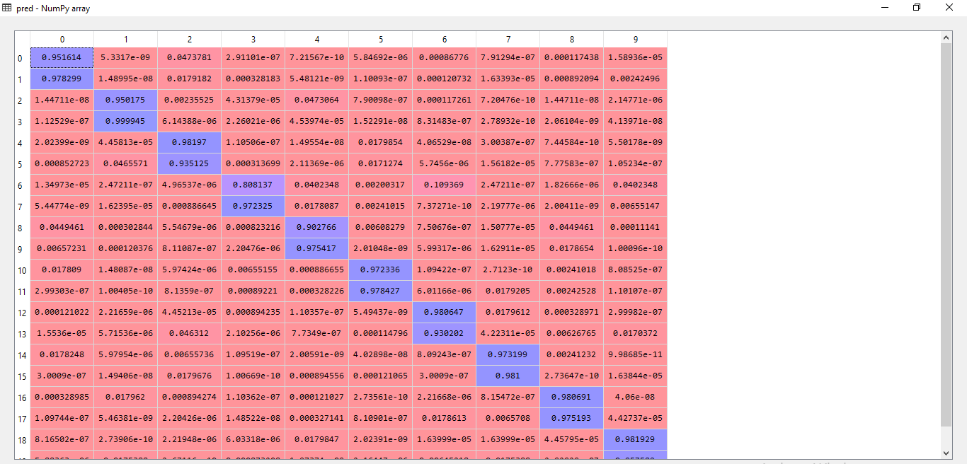 Figure 10 (c): Calculating Accuracy for 10 gestures with 20 images for test II
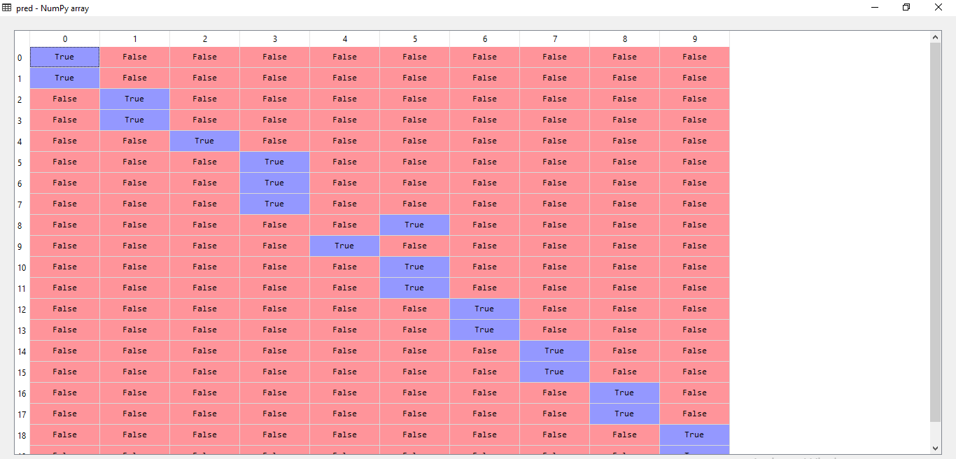 Figure 10 (d): Equivalent Confusion Matrix for Test-II
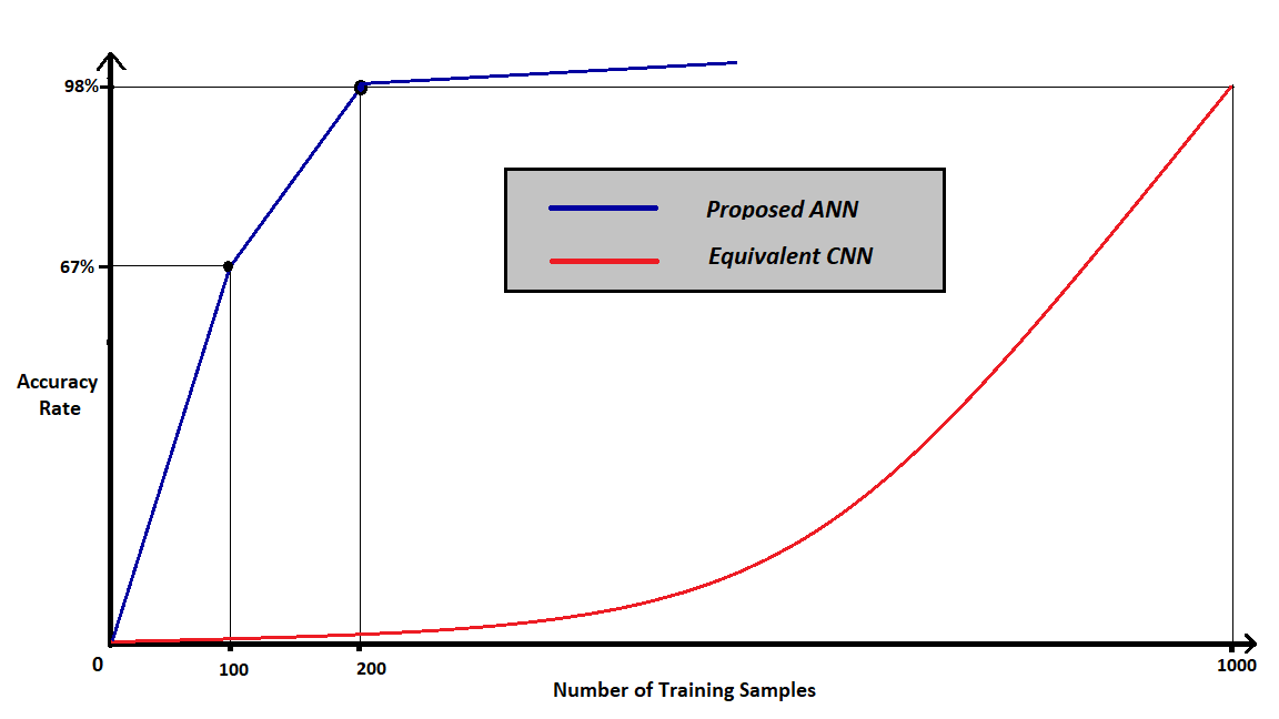 Figure 11: Graphical Explanation of Accuracy versus Number of examples.
4.7. Generation and Training of Feature Vector.
To generate a feature vector, convert the duality (angle and distance) into a singularity is the main challenge. For a given angle and length use a preexisting formula, lsinƟ or the sin component. The following table is a sample of generated feature vector for the data obtained from table 1.
Table 1: Calculating the Elements of Feature Vector
| Length(L) | sin(θ) | Lsin(θ) | |
| P1 | 291.51 | 0.779 | 227.85 |
| P2 | 451.79 | 0.967 | 436.79 |
| P3 | 454.00 | 0.999 | 453.54 |
| P4 | 195.01 | 1.000 | 195.01 |
| P4 | 431.14 | 0.976 | 420.75 |
| P5 | 366.03 | 0.895 | 327.59 |
There are cases where we have found that the number of data points are unequal. As a result, the maximum possible number of data points in a gesture from a given set of gestures is considered as the length of the feature vector array. In case of any gesture having less number of data points than the array size, the empty spaces are filled with 0. This is not analogous to padding with 0, because here it means that the figure has more fingers which are at an angle of 0° or 180°. The feature vector for any gesture is highly distinguished from another gesture.
Once ample number of feature vectors have been obtained, then we can proceed to create our feature file for training the machine. The matrix of features can be created using the feature vectors from the training set. We then train the machine with our matrix of features using Artificial Neural Network and compare the accuracy of each on a common test set.
Data obtained from ten images each of ten alphabets are used for training and testing. Learning is done using ANN classifier. For training and testing we have split the data in 8:2 ratio for each alphabet. Our training set consisted of 10 pictures each of 10 alpha-numeric gestures. Thus we have used 80 images in total to train the machine and further 20 to test the accuracy. Our training included the deployment of cross-validation technique to obtain more precise results. Cross-validation randomizes the data used for training and testing respectively.
5. Results
The aforementioned algorithm has been put to test and has yielded an average accuracy of 92.5%. In reference to the results generated by the code, the confusion matrix of a couple of outputs have been mentioned with resultant prediction values.
In the above stated figures, test 1 has revealed an accuracy of 100% stating that all images of the hand gesture has been successfully classified. The confusion matrix indicates true value for the hand gestures it has predicted for a given feature vector and false for the rest. In the second test the algorithm has missed classified two figures and hence it can be noticed in the confusion matrix where the algorithm has wrongly predicted true for hand gestures numbered 2 and 4 respectively. Additional tests have been conducted in order to obtain consolidate the rate of accuracy.
Table 2: A Comparison between the Proposed Frameworks with the Available CNN
| Proposed ANN | Equivalent CNN | |
| Training Time | 3 minutes for 100 sample | 18 minutes for 100 samples |
| Prediction Time | 1 millisecond | 10 milliseconds |
| Feature Vector Length | 10 | 255 X 255 |
The above figures strengthen the advantages of the proposed algorithm over existing CNN or Convolution Neural Network algorithms. Sample training shows that on an average 3 minutes are required for training our algorithm in comparison to CNN which takes roughly 18 minutes for the same number of images. As stated before, storage requirements are highly minimized due to the miniscule feature vector size and the number of images required to obtain adequate accuracy. Thus, for a considerably lesser number of images the algorithm generates acceptable accuracy in contrast to existing algorithms.
Thus the aforementioned framework is readily available for application on computation constricted environment in public sectors and also in absence of high data processing infrastructures.
An average accuracy of 92.5 % has been secured by our algorithm while observing each cycle of training and testing set obtained using cross-validation technique. In comparison to existing Convoluted Neural Network models (CNN), it requires substantially less data and produces acceptable accuracy. Further CNN is computationally expensive model of prediction in comparison to ANN model coupled with distinctive feature extraction.
6. Conclusion
Our technology and technique for gesture recognition has provided significant improvements over previously worked on methods in terms of accuracy and reliability. The disabilities experienced by individuals who are incapable of speaking are overcome with the help of this machine which eradicates the need of another individual for translation of the sign language to the commonly used English language. We have trained our system with considerably less and manageable sized dataset consisting of various gestures of every letter in the English alphabet. There are some drawbacks, however, in the fact that the process of recognition of a gesture must be carried out with the assistance of a glove without which the creases hinder with the accurate depiction of the hand model and consequently results in imperfect polygon approximation. Also, the process must be carried out in front of a uni-coloured background to ensure that the outer contours of the hand are well defined. But with better and elevated image preprocessing techniques the need for gloves and background may be eradicated. We hope that our research will help the unfortunate ones become socially acceptable and can express themselves spontaneously and freely.
- Y. Xu,Y. Dai, “Review of Hand Gesture Recognition and Application”; Contemporary Engineering Sciences, Vol. 10, 2017.
- T. Messer, “Static hand gesture recognition.” University of Fribourg, Switzerland (2009).
- J. S. Kim, W. Jang, Z. Bien, “A dynamic gesture recognition system for the Korean sign language (KSL).” IEEE Transactions on Systems, Man, and Cybernetics, Part B (Cybernetics) 26.2 (1996).
- M. H. Kim, Y. H. Joo, J. B. Park, “Emotion Detection Algorithm Using Frontal Face Image”; ICCAS2005, June 2-5, KINTEX, Gyeonggi-Do, Korea.
- D. A. Chowdhry, A. Hussain, Rehman, Z. U. R. Muhammad, “Smart Security System For Sensitive Area Using Face Recognition”; 2013 IEEE Conference on Sustainable Utilization and Development in Engineering and Technology (CSUDET).
- C. A. Pickering, K. J. Burnham, M. J. Richardson, “A Research Study of Hand Gesture Recognition Technologies and Applications for Human Vehicle Interaction”, 2007 3rd Institution of Engineering and Technology Conference on Automotive Electronics, 28-29 June 2007, Warwick, UK.
- P. Pandey, V. Jain, “Hand Gesture Recognition for Sign Language Recognition: A Review”; International Journal of Science, Engineering and Technology Research (IJSETR), Volume- 4, Issue- 3, March 2015.
- W. P. Clark, “The Indian Sign Language: With Brief Explanatory Notes of the Gestures Taught Deaf-mutes in Our Institutions for Their Instruction and a Description of Some of the Peculiar Laws, Customs, Myths, Superstitions, Ways of Living, Code of Peace and War Signals of Our Aborigines”, Philadelphia, Pa.: LR Hamersly & Company, 1884.
- W. C. Stokoe, “Sign language structure.” (1978).
- V. Sumalatha, R. Santhi, “A Study on Hidden Markov Model (HMM)”, International Journal of Advance Research in Computer Science and Management Studies, Volume 2, Issue 11, November 2014.
- K.Tang, T.Woo, “Algorithmic aspects of alternating sum of volumes. Part 2: Nonconvergence and its remedy”,
- T. Starner, J. Weaver, A. Pentland, “Real-time american IEEE Transactions on Pattern Analysis and Machine Intelligence 20.12 (1998): 1371-1375.
- K. Selvakumar, “A Review on Polygonal Approximation Techniques of the Digital Planar Curves”, International Journal of Pure and Applied Mathematics, Volume 117 No. 17 2017, 85-90 ISSN: 1311-8080 (printed version); ISSN: 1314-3395.
- Y.S.Kim, “Recognition of form features using convex decomposition”, Computer-Aided Design 24.9 (1992): 461-476.
- J. M., Lien, N. M. Amato, “Approximate convex decomposition of polygons”, Proceedings Of The Twentieth Annual Symposium On Computational Geometry, ACM, 2004.
- C.J. Bajaj, T. K. Dey, “Convex Decomposition of Polyhedra And Robustness”, SIAM Journal on Computing 21.2 (1992): 339-364.
- M. Attene, B. Falcidieno, M. Spagnuolo,“Hierarchical Mesh Segmentation Based On Fitting Primitives”, The Visual Computer. 22. 181-193. 10.1007/s00371-006-0375-x, (2006).
- K.Mamou, G. Faouzi, “A Simple And Efficient Approach For 3D Mesh Approximate Convex Decomposition”, Image Processing (ICIP), 2009 16th IEEE International Conference on Image Processing, IEEE, 2009.
- J. Rekha, J. Bhattacharya, S. Majumder, “Shape, Texture And Local Movement Hand Gesture Features For Indian Sign Language Recognition”, Trendz in Information Sciences and Computing (TISC), 2011 3rd International Conference on Trendz in Information Science and Computing, IEEE, 2011.
- M. R. Ahsan, M. I. Ibrahimy, O. O. Khalifa, “Electromygraphy (EMG) Signal Based Hand Gesture Recognition Using Artificial Neural Network (ANN)”, 2011 4th International Conference on Mechatronics (ICOM), Kuala Lumpur, 2011, pp. 1-6. doi: 10.1109/ICOM.2011.5937135.
- Li, Yuqian, Su, Guangda, “Simplified histograms of oriented gradient features extraction algorithm for the hardware implementation”, 2015 International Conference on Computers, Communications, and Systems (ICCCS) IEEE Xplorer, 2015.
- Z. Ren, J. Yuan, J. Meng, Z. Zhang, “Robust part-based hand gesture recognition using kinect sensor”, IEEE transactions on multimedia 15.5 (2013): 1110- 1120.
- H. Cooper, B. Holt, R. Bowden, “Sign language recognition”, Visual Analysis of Humans, Springer, London, 2011. 539-562.
- Plataniotis, K.N.; Venetsanopoulos, A.N.; “Color Edge Detection. In: Color Image Processing and Applications”, Digital Signal Processing, Springer, Berlin, Heidelberg, 2000.
- E.K. Burke, R.S.R. Hellier, G. Kendall, G. Whitwell , “Complete And Robust No-Fit Polygon Generation For The Irregular Stock Cutting Problem”, European Journal of Operational Research, 179 (2007) 27–49.
- P. Prosser, “Exact algorithms for maximum clique: A computational study.” Algorithms 5.4 (2012): 545-587.