
Acquiring Wi-Fi Energy to Charge a Mobile Phone
Volume 3, Issue 5, Page No 28-35, 2018
Author’s Name: Mohamed Zied Chaari1,a), Mohamed Al-Kuwari1, Rashid Al-Rahimi1, Mongi Lahiani2, Hamadi Ghariani2
View Affiliations
1FAB LAB, Qatar Scientific Club, 9769, Doha- Qatar
2National School of Engineers of Sfax, ENIS, 3000, Sfax-Tunisia
a)Author to whom correspondence should be addressed. E-mail: chaari_zied@ieee.org
Adv. Sci. Technol. Eng. Syst. J. 3(5), 28-35 (2018); ![]() DOI: 10.25046/aj030505
DOI: 10.25046/aj030505
Keywords: Harvesting energy, Mobile charging, Super-capacitor, Radio frequency

Export Citations
As a result, outdoor travelers, tourists and businessman who utilize portable electronic devices often experience battery depletion of their devices without the means of charging their device. The number of Wi- Fi access point continues to increase. There are many occasions where it is desirable to acquire energy from many radio frequency stations, while charging any electronics device through RF-DC circuit with high efficiency, for example, Wi-Fi hotspot access points. We focus on ambient radio frequency signals and power available in the ambient. This research explain, how can we charge portable devices without electrical source but means of propagating signal generated by Wireless-Fidelity (Wi-Fi) router. The research will show all the activities addressed to design a system to recover energy from electromagnetic sources presents around us likeWi-Fi routers. An energy acquiring circuit includes one loop antenna to detect RF signals and electronic board for converting RF energy to DC current. We can use to charge the battery of our portable devices by acquiring the electromagnetic energy around us.
Received: 02 May 2018, Accepted: 01 September 2018, Published Online: 14 September 2018
1. Introduction
Particularly Wi-Fi routers are increasingly used in many places such as coffeehouse, airport, school, mall, etc. So, Wi-Fi access point is available and easy to find in any public place, at home and almost anywhere. There are many high powered Wi-Fi stations whose transmitted signals that create a Wi-Fi hotspot to be implemented are projected to be rather strong signals [1]–[6] in the future. Currently, when we experience our portable devices has no battery charge, we lost an important communication with people around us. We usually encounter this situation when we travel or vacation, at the airport, coffee shop, business trip, etc. Many of us don’t know or neglect that energy from high-frequency radio (RF) signal can be acquire and used as a power supply to our devices. But in this research show how useful it is. The main objective of this work is to acquire the Wi-Fi signals and converting the electromagnetic energy to a DC voltage [7]–[9]. Providing to charge the batteries of an external electronic device connected thereto, or to continuously charge an internal battery within the energy acquiring device until its storage capacity is full, and that battery energy can be reused to power our electronic devices, such as smartphone. From Wi-Fi hotspot and convert the received signal into DC voltage [10]–[15]. RF energy acquiring is acquiring the microwave energy around us and converting it into usable electrical power for electronic devices as shown in Figure 1.
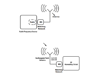 Figure 1: Conceptual view of radio-frequency (RF) energy harvesting
This high technology is also named as power scavenging and power harvesting. The evident summons of acquiring ambient RF energy is that it is essentially free energy. The purpose of this research is to explain and to implement one band of the center operating frequency (f0 = 2.45GHz). One square loop antenna can collect maximum microwave energy from Wi-Fi router with high efficiency and high directivity. The reflected microwave energy converted from microwave signal to DC power. The results are satisfactory and show the advantage of using a square antenna for acquiring microwave energy. The efficiency of the antenna is related to the shape and impedance of the antenna. In this research, we focus on the possibility of charging the mobile phone.
The purpose of this work is related to energy conservation methods, and more particularly related to charging the battery of mobile phone by RF acquiring energy as illustrated in Figure 2.
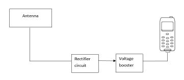 Figure 2: Conceptual view of WIFI harvesting system
This research is organized as follows: in Section 2: We present the measurements of radio frequency exposure from Wi-Fi router. Section 3: The antenna designed method. Section 4: Presents the converter of Wi-Fi signal to DC power. Section 5: We present simulation work and experimental results of fabricated prototype with analyses of data. We describe the simulation and results. Finally, Section 6: Conclusions.
2. Measurements of Radio Frequency Exposure from Wi-Fi router
First of all we should be measures the Wi-Fi signal that people are exposed. The measurements of radio frequency exposure generated by Wi-Fi router using the spectrum and real-time spectrum analyzer SRM3006 [16,17,18,19]. It measures radiating sources at frequencies from 300 MHz to 3 GHz, but it does not display the frequency. We can measure the Wi-Fi field strength in Volts per meter (V/m), and the time-average RF power in uW/m2 as shown in figure 3.
We are measure the quantity of propagated energy around us and we observe that the quantity is very high, it is around 600 mW/m2 at operating frequency (f0 = 2.45GHz). The results obtained after 10 iterations are shown in Figure 4. The main objective of the research is to supply a device that converts the acquired energy (600 mW/m2) from Wi-Fi router into DC (direct current) with high efficiency. The DC energy from which is stored in a super-capacitor (15F/5.6V), and has the capability to connect into electrical power source for restoring power [20]–[25].
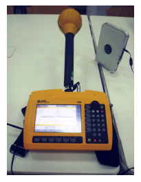 Figure 3: Measurements of radio frequency exposure from Wi-Fi access point
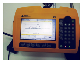 Figure 4: Experimental setup (Wi-Fi Spectrum analysis)
In this research, a provide device for acquiring energy from Wi-Fi access point to power an external electronic device connected thereto smartphone. It is yet a further objective of the present research to supply device for acquiring energy from WIFI power received and convert into a DC (direct current) with high efficiency. The power from which is stored in a supercapacitor (15F/5.6V) device within the device, and which further has the capable to connect into a source of electrical power for storing power. The main objective of the present work is to provide a device which acquires energy from the Wi-Fi router. The bandwidth from 1.45 GHz to 3.6 GHz and the center frequency is (f0 = 2.45GHz). Wi-Fi spectrum analysis allows identifying the power of the signals sources then we can conclude.
3. Wi-Fiharvestingenergyantenna
The antennas generating RF electrical signals in response to the transmitted RF signals received that way and only rectifier circuits [26,27,28,29,30]. The loop antenna collects all energy radio frequency around us and generating a direct current (DC). The radiation field of the loop antenna could be determination using an electric current model. In the electric current model, the current is used directly to find the far-field radiation pattern. The sketches of the square loop antenna is shown below in Figure 5.
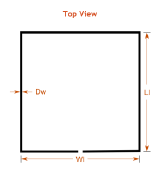 Figure 5: Geometry of the proposed square loop antenna
The bandwidth of the loop antenna is from 1.45
GHz to 3.6 GHz and the center frequency is (f0 = 2.45GHz).
3.1. Equivalent Circuit of a Loop Antenna
Frequently, it is assumed that the loss resistance of loosely harvesting antenna equals the high-frequency loss resistance of a right copper wire of the same length as the loop and of the same current distribution [31,32,33,34,35,36] as shown in Figure 6. In the case of a uniform current distribution, the high-frequency resistance is calculated as
Rh = (l/P )×Rs (1)
where :
l : length of the wire, p : perimeter of the wires cross-section. Cr : resonance capacitor,
Rl : loss resistance of the loop antenna, Rr: radiation resistance,
La: inductance of the loop,
Li: inductance of the loop conductor (wire).
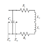 Figure 6: Equivalent Circuit of a Loop Antenna
3.2. Design Parameters
The parameters selected for design a square loop antenna are shown in Table 1.
Table 1: Dimensions of loop antenna
| Name | Parameters | Value |
| Ll | Loop length | 36.56 mm |
| WI | Loop width | 36.56 mm |
| DW | Wire diameter | 2 mm |
| FW | Feed section width | 0.66 mm |
3.3. Simulated and Analysis
In order to construction loop antenna, we use copper wire diameter of 2 mm and loop length equal approximately to the width 36.56mm. The antenna is designed and simulated using Antenna Magus and CST studio microwave software which uses FEM and tetrahedron method to solve and simulate complex 3D electromagnetic (EM) efficiency and uses a feature of the graphical user interface. After simulated our antenna on Antenna Magus and CST software, we calculated parameters like Gain, VSWR, SMITH, Radiation pattern 3D etc.
3.3.1. Gain PLOT
The reflection coefficient (dB) of the proposed loop antenna showing the gain at 2.419 GHz is -26.95 dBi. The gain plot can be seen in Figure 7.
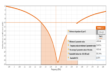 Figure 7: Reflection coefficient Vs frequency (GHz)
3.3.2. VSWR PLOT
VSWR is a measure of how well matched the loop antenna to the SMA connector impedance 50Ω. A perfect result would have a VSWR of 1:1. VSWR obtained from the simulation on antenna magus and CST software is 1.073 at 2.419 GHz which approximately equals to 1:1 as shown in Figure 8. This present the perfect impedance matching of the loop antenna with the port at 50Ω.
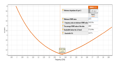 Figure 8: VSWR of proposed antenna
3.3.3. SMITH PLOT
The Smith Chart is very important to estimate the performance of the harvesting antenna [43]. Smith Chart of proposed antenna shows at radiation frequencies 2.419 GHz, inductance is very low. So, Impedance is purely resistive circuit were shown in Figure 9.
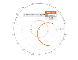 Figure 9: Smith chart of proposed antenna
3.3.4. Radiation pattern 3D
Figure 10 shows the radiation pattern simulated result of gain for the proposed harvesting antenna (maximum E-plane 3.53 dB and minimum E-plane -36.5 dB).
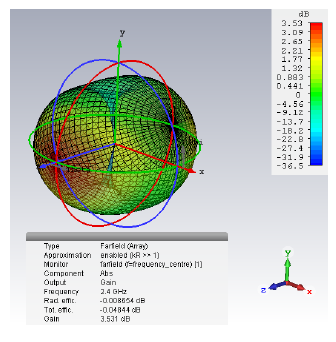 Figure 10: Radiation pattern 3D
3.3.5. Current distribution
Figure 11 shows the simulated current distribution of the proposed antenna for different polarization at different phases..
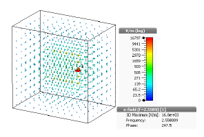 Figure 11: Current distribution of the harvesting antenna
4. RF-DC converter
Figure 12 is a schematic diagram of a first preferred form of an electrical circuit constructed in accordance with present work for acquiring energy from Wi-Fi bands. The energy acquiring circuit, in accordance with this first embodiment, includes an antenna which receives Wi-Fi source, and converts the microwave signals to an electrical signal an RF-to-DC rectifier circuit [44,45]. The rectifier circuit converts the RF signal to a DC (direct current) signal on its output. This DC signal is provided to a first storage device. The first storage device (super-capacitor) stores and accumulates charge thereon from the rectified (DC) signal outputted by the rectifier circuit.
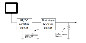 Figure 12: Block diagram for Wi-Fi acquiring energy
4.1. Matching circuit using Advanced design system (ADS)
The maximum microwave power distribution from proposed square loop antenna to the full wave rectifier circuit is ensured by the matching circuit. We are sure that the VSWR obtained from the simulation on CST is 1.073. From the maximum microwave source, the transfer occurs when the circuit is matched with the loop antenna, the impedance matching is mostly performed at the particular input signal [19]. The matching circuit design performs impedance transformation to guarantee maximum power between the antenna and RF-DC converter circuit. A matching circuit as show in Figure 13 that operates at 2.450 GHz the input impedance of 50Ω and the load resistance of 50Ω were made.
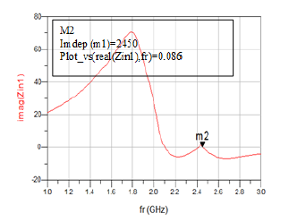 Figure 13: Input impedance versus frequency
4.2. A full bridge rectifier rectenna circuit
After designing a matching circuit, all components are optimized by setting two goals at the same time ; minimizing return loss between 1.4 GHz and 3.6 GHz and maximizing the DC output voltage. To design the full wave bridge rectifier using HSMS 2820 diode for microwave energy circuit, the following components in figure 14 were used [46]. The output voltages as a function of time for an input power of 2.450 GHz and the simulated value. The Pin versus load are presented in figure 15 and figure 16, respectively. In addition, figure 17 shows the output current (A) in the load circuit. The maximum output voltage shows 0.0025A at 6 dBm.
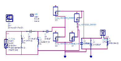 Figure 14: Schematic diagram of microwave harvesting circuit of full wave bridge rectifier with HSMS 2820 diode (Agilent ADS)
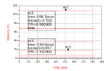 Figure 15: Simulation of the output voltages
The simulation shows the output voltage (V) of the circuit using the full wave bridge rectifier circuit. It can be observed that using an HSMS 2820 diode enables to generate a power around 102 mW, as shown in figure 15.
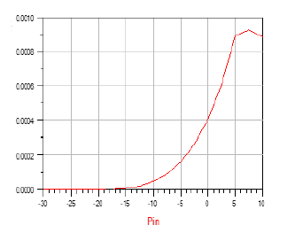 Figure 16: The simulation output power (w) of one stage circuit
The Figure 17 shows the output current of the circuit using the full wave bridge rectifier circuit. It can be observed that using an HSMS 2820 diode enables to generate a DC current around 0.0025 A.
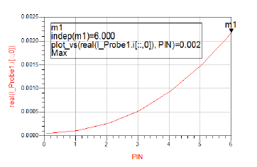 Figure 17: The simulation output current (I) of the full wave bridge rectifier circuit
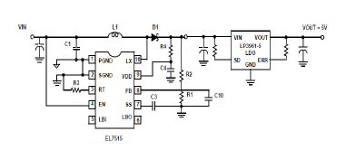 Figure 18: A voltage booster circuit
4.3 A voltage booster circuit
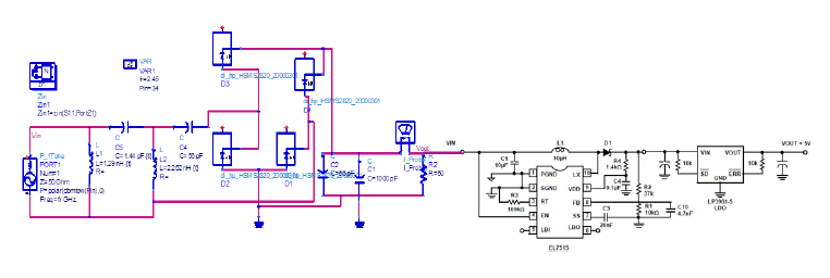 Figure 19: RF harvesting electronic circuit and power changing
The voltage on the super capacitor (15F/5.6V) is also provided to the input of DC-to-DC converter circuit, which acts as a charge pump. Polarized energy storage capacitor with high capacity. A voltage booster integrated circuit was used to try to boost the voltage outputted by the RF/DC circuit to 5 V, can charge the battery of mobile phone. This integrated circuit can be used to boost a low-voltage variable input (1.8 V 9 V) to a constant 5 V can charge the battery of mobile phone. The integrated circuit LP3961EMP-5.0 it is linear regulators circuit can provide +5V/ 0.8A. The circuit is shown in Figure 18.
5. Simulation results
More specifically, the antenna is coupled to the rectifier circuit, which converts the Wi-Fi radiating source into a DC voltage multiplied. The energy acquiring device of the present work is capable of receiving microwave power from 1.440 GHz to 3.6 GHz, and convert the received signals into electrical energy, as illustrated in Figure 19.
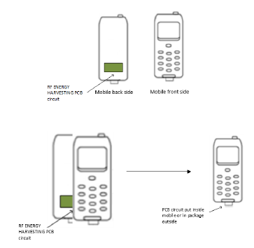 Figure 20: Method assembly of PCB circuit
Provided above is a general description of the purpose and implementation of the energy acquiring method and apparatus of the present research. The results obtained in the different simulation are remembered in Table 2.
Table 2: Simulated results
| Performance parameters | Value |
| Maximum gain value (dBi) | 4.013 |
| Minimum gain value (dBi) | 2.711 |
| Bandwidth | 40 % |
| VSWR | 1.073 |
This work present propose method assembly of PCB circuit, the assembly method and the topology to put the PCB circuit inside the mobile phone. The circuit are presented in Figure 20 and Figure 21, respectively.
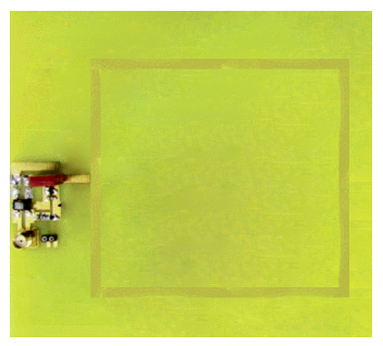 Figure 21: PCB circuit
6. Conclusion and Outlook
In this research, a new method for wireless charging the mobile phone by acquiring Wi-Fi energy. The idea is to acquire a maximum energy while other is charging or using their electronic devices. The present research paper we are tested and proven that we can generate voltage from Wi-Fi access radio frequency to power and charge a battery of any electronic devices. Future goals of this work is to acquire energy from any signal around us like Wi-Fi, GSM, VHF, UHF, etc. We can change the topology of rectifier circuit and the design of loop antenna and check if we can acquire more energy or not. The most important that we have one prototype for this work and try to improvement in the future work.
- John Ross, A Painless Guide to Wi-Fi and Broadband Wireless 2nd Edition, 2008.
- Steve Pease, WI – FI: HOW TO BOOST YOUR WI – FI SIGNAL: Get the wi – fi and internet access you need all over your house Kindle Edition, 2016.
- Icon Group International , The 2019-2024 World Outlook for Gigabit Wi-Fi Access Points, 2018.
- Icon Group International ,The 2019-2024 World Outlook for Carrier Wi-Fi Access Points and Controllers, 2018.
- Alliance for Telecommunication Industry Solutions , ATIS ATIS-0600015.13.2017 Energy Efficiency for Telecommunication Equipment: Methodology for Measurement and Reporting of 802.11xx Wi-Fi Access Points, 2017.
- Joseph Epstein, Scalable VoIP Mobility: Integration and Deployment 1st Edition, Elsevier, 2009.
- M. Hadi Habaebi, N. Izzati Nabilah Bt Azizan, ”Harvesting WiFi Received Signal Strength Indicator (RSSI) for Control/ Automation System in SOHO Indoor Environment with ESP8266”, 2016 International Conference on Computer and Communication Engineering (ICCCE), 416 – 421, 2016.
- Xuelin Chen, Lianfen Huang, Jianli Xing, Zhiyuan Shi, Zuosheng Xie,”Energy harvesting system and circuits for ambient WiFi energy harvesting”,12th International Conference on Computer Science and Education (ICCSE), 769 – 772, 2017.
- Jingjing Wang, Chunxiao Jiang, Zhu Han, Yong Ren, Lajos Hanzo,” Network Association Strategies for an Energy Harvesting Aided Super-WiFi Network Relying on Measured Solar Activity”,IEEE Journal on Selected Areas in Communications, 3785 – 3797, 2016.
- Lidiya Mary Lawrence, Jobin K Antony, ”Design and performance analysis of RF to DC converter for wireless sensors” , 2nd IEEE International Conference on Recent Trends in Electronics, Information Communication Technology (RTEICT), 1660 – 1665, 2017.
- A. Almansouri, M. Ouda, K. Salama,”A CMOS RF-to-DC Power Converter With 86% Efficiency and -19.2-dBm Sensitivity” IEEE Transactions on Microwave Theory and Techniques, 1-7, 2018.
- R. Correia, N. Carvalho,”HEMT based RF to DC converter efficiency enhancement using special designed waveforms”, 2017 IEEE MTT-S International Microwave Symposium (IMS), 609-612, 2017.
- Sanjeev K, Manjunath Machnoor, K. J. Vinoy, T. V. Prabhakar,”A high efficiency 2.4GHz RF to DC converter using 130nm CMOS Cross-Coupled Rectifier”,2016 Twenty Second National Conference on Communication (NCC), 1-4, 2016.
- H. Ouda, W.khalil, N. Salama,”Wide-Range Adaptive RF-to- DC Power Converter for UHF RFIDs”,IEEE Microwave and Wireless Components Letters, 634-636, 2016.
- CHAN CHUN YEW,”DESIGN OF RECTIFYING CIRCUIT WITH IMPROVED RF-DC CONVERSION FOR WIRELESS POWER TRANSFER”,Ph.D Thesis, UNIVERSITI TEKNIKAL MALAYSIA MELAKA , 2015.
- Zaln Horvth, Ferenc Csikor,”Personal Electromagnetic Exposure Measurements in the Radiofrequency and Microwave Range”,Ph.D Thesis, Etvs Lornd University, 2012.
- Finta V, Vradi L, Juhsz P, Kiss , Thurczy Gy,” A Method for Personal RF Exposure Assessment of Children”, EMF Health Risk Research: Lessons Learned and Recommendations for the Future, workshop poster, 2012.
- G. F. Pedersen and J. B. Andersen, ”RF and ELF exposure from cellular phone handsets: TDMA and CDMA systems,” Radiation Protection Dosimetry, 131-138, 1999.
- S. Iskra, B.W. Thomas, R. McKenzie, and J. Rowley, ”Evaluation of potential GPRS 900/1800-MHz and WCDMA 1900-MHz interference to consumer electronics,” Ieee Transactions on Electromagnetic Compatibility, 951-962, 2005.
- G. Wang, L. Zhang and J. Zhang, ”A review of electrode materials for electrochemical supercapacitors”, Chem. Soc, 797-828, 2012.
- H. Wu, G. Yu, L. Pan, N. Liu, M. T. McDowell, Z. Bao and Y. Cui, ”Stable Li-ion battery anodes by in-situ polymerization of conducting hydrogel to conformally coat silicon nanoparticles”, Nature Communications, 2013.
- M. S. Halper, J. C. Ellenbogen, Supercapacitors: A Brief Overview, MITRE, 2006.
- C. Liu, Z. Yu, D. Neff , A. Zhamu, and B. Z. Jang, ”Graphenebased supercapacitor with an ultrahigh energy density”, Nano Lett., 4863-4868, 2010.
- B. E. Conway and W. G. Pell, Double-layer and pseudocapacitance types of electrochemical capacitors and their applications to the development of hybrid devices, J.Solid State Electrochem., 637644, 2003.
- C. Mid-Eum and S. Seung-Woo, Robust energy management of a battery/supercapacitor Hybrid Energy Storage System in an electric vehicle, presented at the Electric Vehicle Conference (IEVC), 2012 IEEE International, 15,2012.
- Muhammad S Khan, Hai Deng,”Design and implementation of a highly efficient UHF energy harvesting antenna”, IEEE International Symposium on Antennas and Propagation (APSURSI),611-612, 2016.
- Hirokazu Kamoda, Shoichi Kitazawa, Naoya Kukutsu, Kiyoshi Kobayashi,”Loop Antenna Over Artificial Magnetic Conductor Surface and Its Application to Dual-Band RF Energy Harvesting”, IEEE Transactions on Antennas and Propagation, 4408 – 4417, 2015.
- Youssef Tawk, Joseph Costantine, Firas Ayoub, Christos G. Christodoulou,”A Communicating Antenna Array with a Dual- Energy Harvesting Functionality”,IEEE Antennas and Propagation Magazine, 132-144, 2018.
- Mamta Kurvey; Ashwini Kunte,”Design and optimization of stepped rectangular antenna for RF energy harvesting”, International Conference on Communication information and Computing Technology (ICCICT),1-4, 2018.
- Jingna Mao, Jian Zhao, Huazhong Yang, Bo Zhao,”Using human body as a monopole antenna for energy harvesting from ambient electromagnetic energy”, IEEE Biomedical Circuits and Systems Conference (BioCAS),1-4, 2017.
- S. Hayashida, T. Tanaka, H. Morishita, Y. Koyanagi, and K. Fujimoto, Built-in folded monopole antenna for handsets, Electron. Lett, pp. 15141516, 2004.
- B. Jung, H. Rhyu, Y. J. Lee, F. J. Harackiewicz, M. J. Park, and B.Lee, Internal folded loop antenna with tuning notches for GSM/GPS/DCS/PCS mobile handset applications, Microw. Opt. Technol. Lett.,vol. 48, pp. 15011504, 2006.
- C. Y. D. Sim, P.-C. Cheng, and C.-H. Lee, Multiband loop antenna design for mobile devices, Microw. Opt. Technol. Lett., vol. 51, pp. 22422248, 2009.
- B.-P. Su, M.-K. Sung, and G.-Y. Woon, Broadband internal antenna by combination of a loop type antenna and a shorted monopole, Microw. Opt. Technol. Lett., vol. 50, pp.28102812, 2008.
- Chia-Hao Ku, Hsien-Wen Liu, Sheng-Yu Lin, Folded Dual-Loop Antenna for GSM/DCS/PCS/UMTS Mobile Handset Applications, IEEE Antennas and Wireless Propagation Lett., vol. 9, pp. 998-1001, Oct. 2010.
- H. Jairam, ”Novel blade antenna using microstrip patch elements,” in Microwave Conf., 19th European, London, UK, 1989, pp. 1118-1122.
- Z. Novacek, ”Radiation of a whip antenna on the car body,” Radioelectronika, 17th Int. Conf., Brno, June 2007, 1-4.
- A. Walbeoff and R. Langley, ”Multiband PCB antenna,” Proceedings of IEE Microwaves, Antennas and Propag., Centre, Sittingbourne, UK, Dec. 2005, 471-475
- F. Mariottini, M. Albani, E. Toniolo, D. Amatori, and S. Maci, ”Design of a compact GPS and SDARS integrated antenna for automotive applications,” Antennas andWireless Propag. Lett., IEEE, 405-408, 2010.
- S. Choi, H. Lee, and K. Kwak, Circularly Polarized H-Shaped Microstrip-Array Antenna with a T-Slot for DSRC System Roadside Equipment, Microwave and Optical Technology Letters, pp. 1545-1548, 2009.
- G. Whyte, Antennas forWireless Sensor Network Applications, Ph. D. Thesis, University of Glasgow, Glasgow, United Kingdom, 2008.
- C. Balanis, Antenna Theory: Analysis and Design, 3rd ed, Wiley, Hoboken, New Jersey, 2005.
- A. Heidari, M. Heyrani, M. Nakhkash, A Dual-Band Circularly Polarized Stub Loaded Microstrip Patch Antenna for GPS Applications, Progress in Electromagnetics Research, PIER 92,195-208, 2009.
- Luis Filipe Ribeiro Dias, Alrio Boaventua, Nuno Borges de Carvalho,”RF-DC converter efficiency optimization using source-pull techniques”, InternationalWorkshop on Integrated Nonlinear Microwave and Millimetre-wave Circuits (INMMiC), 1-3, 2014.
- M. Roscia, D. Zaninelli, G. C. Lazaroiu; H. Shadmehr,”Using design optimization in radio frequency energy harvesting systems”, International Conference on Clean Electrical Power (ICCEP), 740-744, 2013.
- Faruk Erkmen; Thamer S. Almoneef; Omar M. Ramahi,” Electromagnetic Energy Harvesting Using Full-Wave Rectification”, IEEE Transactions on Microwave Theory and Techniques, 1843- 1851, 2017.