IR Sensing Embedded System Development for Prototype Mobile Platform and Multisensory Data Fusion for Autonomous Convoy

Adv. Sci. Technol. Eng. Syst. J. 3(4), 372–377 (2018);
 DOI: 10.25046/aj030438
Advanced sensing technologies are providing for greater capabilities to discern and classify details of objects as they appear in actual environments as experienced by nonprofessional drivers. Distinctive geometric configurations of new sensory devices including but not limited to infrared (abbreviated as IR) and LIDAR sensory units are appearing as cost effective data acquisition systems for environment sensing and presenting. Here, we describe a novel IR sensory-based autonomous vehicle guidance and its associated convoy unit. The underlying systems is first presented in a general system model and the experimental test results have been elaborated to demonstrate the usefulness of the presented prototype in futuristic auto industries and its supporting branches, respectively.
1. Introduction
As edge cities continue to emerge, drivers are seeking to increase their productivity during commute time and self-driving vehicles are expected to be facilitating platforms. The Boston Consulting Group and the World Economic Forum have been collaborating for the past several years and forecasting that 14% of residents will ultimately expect safe autonomous vehicles [1]. This paper examines the performance of an infrared (IR) sensing using a prototype mobile platform for autonomous vehicle convoy following. The IR spectrum sensing for autonomous vehicle applications is a compelling approach to detecting objects in the path of vehicle travel. Since cost, reliability, and detection performance are the critical criteria for technology production, the study of performance is the primary interest in this work. Beyond the practical benefits, autonomous cars could contribute $1.3 trillion in annual savings to the US economy alone, with global savings estimated at over $5.6 trillion[2]along with a technology adaptation time line as shown in Figure 1. Design of self-driving or autonomous vehicles with smart sensing systems will positively impact planning decisions for optimal traffic flow, minimize traffic congestions, and alleviate human error leading to personal injuries or property damage. As commuters elevate expectations for their time efficiencies during travels it is expected that technology developers reduce the potential for crashes due to driver fatigue, poor maneuvering decisions, and negligence.[3],[4],[5].
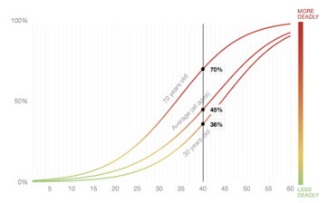 Figure 1. Trends of serious injury vs. vehicle speed in mph.
The curves in Figure 1 is derived comes from typical driving research conducted by AAA Foundation which clearly indicated the probability of getting seriously injured increases with increases in driving speeds. The research also notes these trends depend on several other factors such as size of car, angle of impact, and perhaps age. Autonomous driving systems can aid in reducing or eliminating in the severity of slope in the curves as computed from a small sample size. Cost appears to be a primary driver factor at the onset systems design requirements. To this end, low-cost IR sensing is the motivated attribute to tackle with a vehicle subsystem implementation by noting that IR sensory data acquisition apparatus is capable of sensing surroundings by means of measuring the temperature differences between two vehicles in motion. The vehicle sensor set with field of view (FOV) typically varying from 120o to 150o, and the respective processing software are imperative for safe operation of autonomous vehicles (AVs). Characterizing the performance of sensing to determine the location of the host vehicle relative to other moving vehicles, all in path targets and road lane boundaries are equally important. Human driver sensing reports that approximately 90% of the primary factors behind crashes are due to human errors (see the statistics of the National Highway Traffic Safety Administration (NHTSA) in 2012). [6],[7] AVs with a high performance sensor suite are predicted to reduce crashes and injury rates by upwards of 50% as compared to non-AVs. Vehicle manufactures are motivated to contribute to transformative and highly beneficial technologies to support Intelligent Transportation Systems (ITS) and the future of the mobility industry. The state of the art reports the rationale for selection of IR sensors rather than ultrasonic sensors, RADARs, or cameras to perform the sensing function. This research proceeds with a conceptual design, implementation, testing, and verification of an IR sensor set interfaced to a single board computer. A desired outcome is to follow a vehicle that is remotely controlled. This vehicle is denoted as RC (remote controlled) down scaled-model vehicle. In the literature, Kou et al. employed two low cost sensors using a kinematic model of a car-like mobile robot (CLMR). [8] Chao-Lin Kuok et al., devised to compare two non-linear model-based approaches for autonomous vehicles. [9] Carson et al., and Englund et al. studied safety criteria for driver assisted systems and enabling technologies. [10],[11] Paden et al. investigated a decision-making hierarchy (i.e., route planning, behavioral decision making, motion planning, and vehicle control) for driverless vehicles. This paper is organized as follows. Section II describes the overall system configuration and sensor interfaces to accomplish the autonomous tracking capability. Here, we also present the embedded system design. Section III is devoted to the testing and the IR sensor configuration. We then describe analysis of the measured test results in Section IV. Section V provides a discussion and the conclusion.
2. Formulation of Research Project
This section describes the design and implementation of an embedded system onto the scale of 1/10 of remote controlled (RC) autonomous vehicles. The system design for this embedded system began by conducting tradeoff study between the Arduino and Raspberry Pi single board computers. In view of ease of programming, a large suite software algorithm readily available in the open source domain. Hence, the decision we have chosen the Raspberry Pi Model B+. It is a fully featured very compact computer operating at 700 MHz and uses the Raspbian Operating System (OS). The computer interface circuitry has mainly 7 components; namely,
- 4 Universal Serial Bus (USB) 2.0 slots
- Single storage data card slot
- 24 Pin Header
- Ethernet port
- Customer Support Identifier (CSI) connector for a camera
- High-Definition Multimedia Interface (HDMI) output
- Power from micro-USB Connector
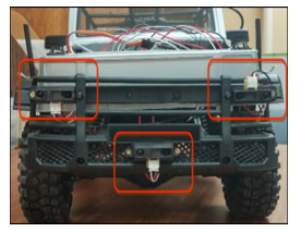 Figure 2. Mounting of IR sensors
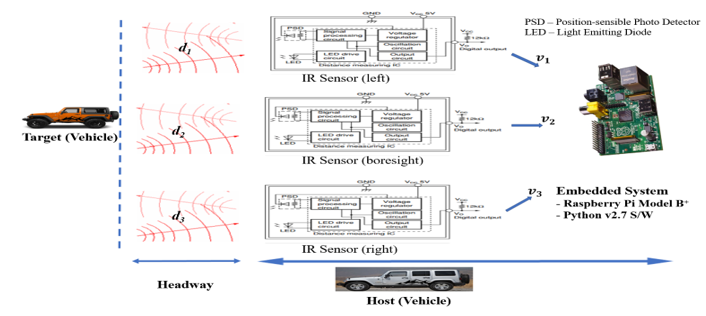 Figure 3. Autonomous convoy embedded system design. [16]
Since cost is always a consideration, an inexpensive SharpGP2YOD21YK IR Sensor operating at the wavelength λ=780 nano-meter (nm) is selected. [12]. The next step is to determine the optimal Field of View (FOV) for forward coverage on the model robotic vehicle. Figure 2. Depicts the mounting of three IR sensors. Specifically, the sensors are mounted in the headlight areas and lower front center of the RC controlled model. Work proceeds to install, calibrate and independently test the sensor in a standalone modes to consume less energy and to operate with nonlinear characteristics [9].
The relationship between the distance di and the operating voltage is inversely proportional, and it is given as
![]() with k being the scaling constant and a is the exponent of proportionality. Equation (1) is empirical formula and for the given Sharp GP2YOA21YK IR sensor, it is specified as
with k being the scaling constant and a is the exponent of proportionality. Equation (1) is empirical formula and for the given Sharp GP2YOA21YK IR sensor, it is specified as
![]() where distance d in cm, K is a corrective constant, ADC is the digitized output voltage, b and c are variable constants to be evaluated from trend line equation. Besides proposed equation (2), the governing sensor equation (3) has three variables (b, c, and K) which are evaluated from the measured data.
where distance d in cm, K is a corrective constant, ADC is the digitized output voltage, b and c are variable constants to be evaluated from trend line equation. Besides proposed equation (2), the governing sensor equation (3) has three variables (b, c, and K) which are evaluated from the measured data.
The embedded Time-Division Multiplexing (TDM) system is implemented by discrete electronic components mounted on a Printed Circuit Board (PCB). The hardware is physically mounted into the body of the robotic model vehicle. Also, it is evident that the data streaming from sensors are converted into a single signal by segmenting the signal with short durations. Figure 3 shows the electrical interface and message traffic block diagram of the Sharp IR sensor in which the digital output Vo is directed to the digital I/O channel of a single board computer (i.e., Raspberry Pi Model B+) [14][15]. This prototype design minimizes the sensor wiring and power connections.
The Python 2.7 language is employed to write the IR sensing system software illustrated in Figure 3. The algorithm is designed using classical Proportional Integral Derivative (PID) controller techniques. Specifically, the PI algorithm is selected as automatic, greater, and basic [17] to implement. SP is defined as a headway or fixed distance and independent of the measurement sensor PVs are the computed distances, shown in Figure 3. “PIDSYS” a MATLAB R2017A based function is utilized to return the parallel form of a continuous-time PI controller shown in Figure 4.
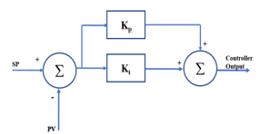 Figure 4. Block Diagram for PI controller.
Here, the instances of error are corrected by proportional term (Kp) corrects and the accumulation of error is corrected by integral term (Ki) corrects the. Based on the rise and fall of error signal {e(t)}, the amount added to the Controller Output (CtrlOut) increases or decreases immediately and proportionately. The CtrlOut is governed by Equation 3 and is given by
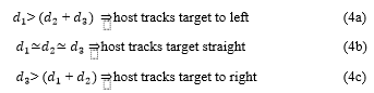
![]() where the range of integration is [0, t], and e is error e = SP-PV required to achieve the controller output. The host vehicle track
where the range of integration is [0, t], and e is error e = SP-PV required to achieve the controller output. The host vehicle track
was based on the sensor voltages and the distances computed, independent of sensor specifications, that occurs per Equation 4.
 The last stage of this research project formulation is to test the PI algorithm and ensure it is properly tuned or adjusted by starting with low proportional and no integral. The values of Kp and Ki are returned as 1.14 and 0.454, respectively. Figure 5 presents the deviation error of measured PV from SP in response to the computation of step response for this PI controller.
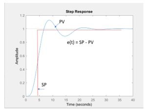 Figure 5. Step response for AV PI controller
3. Analysis of Test Results
After some troubleshooting and software debugging, smooth hallway surfaces are used to perform the initial simulation trials with the embedded system on the host vehicle following a lead vehicle where a smooth following is demonstrated for several test conditions. Figure 6 depicts static photos of the host vehicle chasing the target vehicle in the actual demonstration of this embedded system. The IR sensors are use in individual configurations (i.e., degraded FOV) or by combining that which addresses the redundancy of a given number of sensors
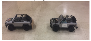 Figure 6. Host tracks target as per equation (4)
4. Data Fusion and Simulation
Sensor fusion is the most important and critical process for autonomous vehicles on the road for increased safety. The short comings of individual sensor can be overcome by fusing the data in such a way that each sensor can complement or augment in the presence of the other sensor failure. The failure or the malfunctioning of the sensors installed could cause by a natural phenomenon or manmade phenomenon [18]. In this parlance, the adaption of the sensor fusion methodology can maintain the essential functions for a required level of safety. With these insights, this section presents the advantage of using Kalman filter-based data fusion over single IR sensor and amid individual sensor failure. Equation 2 is utilized for range tracking and a complete mathematical modeling and simulation based on optimal state estimation theory is presented. With assumed and known values of measurement errors caused by system noises, an optimal estimator computes and processes the measurements for reducing the state error estimate using measurement system dynamics [19].
- System Dynamic Model
The system dynamic model is a generic representation given by
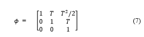
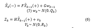 where is a priority or the initial estimate of taken as [6,1,1] for the purpose of this simulation. F or ϕ is denoted as the state transition matrix for predicting the future states and is given as
 Here, the process noise wk and the measurement noise vk are modeled as white Gaussian noise with mean of zero and standard deviation of one. The noises in IR sensor and systems are described as statistical fluctuations or distortions in electrical current modeled by various mathematical models as [20]
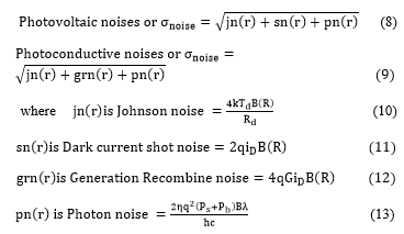 For a particular sensor and with its specifications the measurement noise variances can be modeled by using the equations from 12 to 17.
- Fusion Algorithm
For the purpose of simulation, the sensor and the system are considered as time invariant systems in which all three IR sensors produce measurement at the same time. The method of the fusion process [21] depend on the covariance matrix and its trace operation, given by
![]() where N is the total number of IR sensors mounted on the convoy, z(k) denotes the sensor value from the ith IR sensor for every time interval k, and the quotient ai is given by
where N is the total number of IR sensors mounted on the convoy, z(k) denotes the sensor value from the ith IR sensor for every time interval k, and the quotient ai is given by
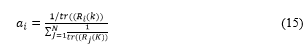 where tr() performs the trace operation with mapped measurement covariance Ri(k) of the ith IR sensor at kth time interval. The quotient ai is summed to unity by assumption.
- Kalman Filter steps
Measurements from each sensor are fused using the below algorithm [21]:
The bock diagram describing the system, measurement model, and discrete-time Kalman Filter is shown in Figure 7.
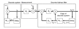 Figure 7. System model and Discrete Kalman filter [22]
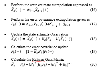
The initial values for predicted covariance and state transition matrix are taken as
 Figure 7 presents the iterative recursion process of the Kalman filter and sums up the equations described in 17 to 21. The simulation results shown in the Figures 9 and 10 describe the effectiveness of Kalman filter-based data fusion. These iterative recursive filters are used for continuous time problems and considered as a breakthrough for estimation in linear dynamic systems. The propagation of covariance matrix and the dynamic calculation of the Kalman filter gains make this filter superior. The state vector dimension is 3-by-1 known as one dimensional third order filter tracking with one position or relative distance component, one velocity component and one acceleration component obtained by each individual IR sensor. The measurements from each sensor are fused using the algorithm and the fused measurement is optimally estimated by the filter steps mentioned in equations 17 to 21. Next, using the state estimate and the covariance matrix the propagation of prediction and correction will continue to obtain the smoothed estimate.
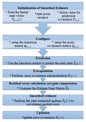 Figure 8. Iteration steps for Kalman filter [23]
Figures 8 presents the MATLAB simulation flowchart. Figure 11 indicates the digitally computed true distance between the target vehicle and the sensor mounted vehicle simulated based on the equation 2. It also shows the measured distances d1, d2 and d3 from each IR sensor and fused distance estimate based on Kalman filter.
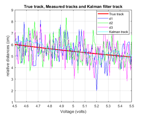 Figure 9. Tracks simulation
The simulation parameters are chosen such as sampling interval of 0.1 sec over the supply voltage values between 4.5 volts to 5.5 volts. The initial values of relative distances d1, d2 and d3 are 6.2, 5.8 and 7.1 cm. These values of relative distances are chosen based on the distance measuring range of the sensor considered in section 2. For each sample the values of d1, d2 and d3 vary between minimum of 4 cm to a maximum of 7 cm. Also, the minimum and the maximum values of true values of track is 4.9 cm to 6cm, and from Figure 10 it is evident that Kalman filter track has the best estimate that follows the true track closely. Table 1 shows the RMS errors and the performance of each sensor and the Kalman filter is analyzed by computing the distance error in relative position between the two vehicles using
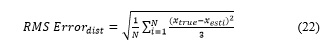 In equation 22, xrue are the true track values and xesti are the individual estimates of each sensor and Kalman filter estimates as well. Therefore, using the equation 22, the RMS error values for each sensor tracks alongside the Kalman filter based fusion tracks are obtained and presented in Table 1.
 Figure 10. RMS errors in relative distances
From Figure 10 and Table 1, it is evident that Kalman filter based fusion method shows the better performance compared to individual IR sensors and the superiority and the advantage of implementing optimal estimation based fusion process.
Table 1. Average RMS Errors
| Estimator | RMS Error (cm) |
| IR sensor 1 | 0.0230 |
| IR sensor 2 | 0.1893 |
| IR sensor 3 | 0.016 |
| Kalman filter based fusion | 0.015 |
Conclusion
This research project resulted in the successful development and implementation of an embedded system design for an autonomous vehicle. The implementation based on theoretical multisensory data fusion is based upon IR sensors and a single board computer. A dynamic demonstration of active following by the host is successful and was accomplished while considering the design constraints of the embedded system. The performance achieved on the 1:10 scaled model indicates positive proof of concept for real-world scaling of OEM (Original Equipment Manufacturer) vehicles. The system architecture provided for sensors from varied range of specifications to be incorporated and demonstrate performance of maintaining a set headway and smoothly following a target vehicle. From the test results, an overall error is found to be less than 5% in following distance and a measurement order of eight seconds resulted in response to steady state. A comparison to other research results reported in the literature confirms similar result where the trade of is use of two sensors (i.e., narrower FOV) whereas this work utilized a configuration of three sensors ((i.e., broader FOV). Also, the incorporation of the fusion applications for the robustness of distance and tracking, could potentially improve the safety considerations. Research results included determination of the system RMS error based on Kalman filter which provides greater accuracy than other computational approaches for error calculations. As error is reduced, AV operational safety will be enhanced. The average RMS error for the lower IR sensor (i.e., centered position and single sensor configuration) is within +/- .001cm. Furthermore, the contextual practical application of the sensor fusion for automotive applications reliability detects in-path targets that aid in collision avoidance. This research maybe be extended by configuring dissimilar sensors such as RADAR, LiDAR in conjunction with IR sensors leading to an Advanced Driver Assistance System (ADAS). These systems are totally dependent on weighting sensor information to make intelligent and safe decisions. Based on the theoretical simulation of sensor fusion presented in the paper, it is believed the paradigm of data fusion can enhance the reliability and robustness of an ADAS for improved safety considerations. The future scope of this research will be demonstrated in the real-world environment amid poor visible conditions to check the accuracy of the proposed methods outlined above. An approach may include resolving distances based on the speed of light by measuring the Time-of-Flight (ToF) between the sensor and the targeted image using a ToF Camera or LIDAR. Motion planning conducted by a low-level feedback controller is also a consideration for additional research since trajectory and path planning are computationally complex and require computing resources well beyond the selected Raspberry Pi Model B+ single board computer.
- N. Lang et al., “Making Autonomous Vehicles a Reality: Lessons from Boston and Beyond., The Boston Consulting Group, Oct. 2017.
- A. Jonas et al., “Autonomous Cars: Self-Driving the New Auto Industry Paradigm,” Morgan Stanley Blue Pap., pp. 1–109, 2013.
- L. Gannes, “Google Introduces New Self Driving Car at the Code Conference,” Re/code. 2014.
- L. Mearian, “Nissan plans to offer affordable self-driving cars by 2020,” Computerworld. 2013.
- D.A. Dickmanns and D. L. Wiesenthal, “Traffic congestion, driver stress, ana driver aggression,” Agbressive behavior, pp 409 – 423, 1988.
- NHTSA, “U.S. Department of Transportation releases policy on automated vehicle development,” Nhtsa 14-13, 2013.
- C. Pozna and C. Antonya, “Issues about autonomous cars,” in SACI 2016 – 11th IEEE International Symposium on Applied Computational Intelligence and Informatics, Proceedings, 2016.
- C. L. Kuo, N. S. Pai, Y. P. Kuo, and Y. C. Hu, “Following method for a car-like mobile robot using two IR sensors,” in IEEE International Conference on Control and Automation, ICCA, 2014.
- E. Alcal; et al., “Comparison of two non-linear model-based control strategies for autonomous vehicles,” 2016 24th Mediterranean Conference on Control and Automation (MED). 2016.
- O. M. G. Carsten and L. Nilsson, “Safety assessment of driver assistance systems,” Eur. J. Transp. Infrastruct. Res., 2001.
- C. Englund et al., “Enabling technologies for road vehicle automation,” in Road Vehicle Automation 4, 2017.
- Sharp Corporation, “Distance Measuring Sensor GP2YOA21YK,” 2016.
- B. Paden et .al, “A Survey of Motion Planning and Control Techniques for Self-driving Urban Vehicles., IEEE Transactions on Intelligent Vehicles, pp. 33-55. Volume: 1, Issue: 1, March 2016.
- Raspberry Pi Foundation, “Raspberry Pi – Teach, Learn, and Make with Raspberry Pi,” www.raspberrypi.org, 2012.
- E. Upton and H. Gareth, Raspberry Pi User Guide. 2014.
- D. Gunnarsson, S. Kuntz, G. Farrall, A. Iwai, and R. Ernst, “Trends in Automotive Embedded Systems,” in CASES’12: Proceedings of the 2012 ACM International Conference on Compiliers, Architectures and Synthesis for Embedded Systems, 2012.
- R.-E. Precup, A.-D. Balint, E. M. Petriu, M.-B. Radac, and E.-I. Voisan, “PI and PID controller tuning for an automotive application using backtracking search optimization algorithms,” SACI 2015 – 10th Jubil. IEEE Int. Symp. Appl. Comput. Intell. Informatics, Proc., 2015.
- Hannes Estl, “Sensor Fusion: A Critical step on the road to autonomous vehicles”, Automotive ADAS sector, April 11th 2016.
- A. Gelp et al, “Applied optimal estimation”, Second edition, MIT press, February 1974.
- Christopher W. Keefer, “Infrared Target Detection: Signal and Noise Sensitivity Analysis”, Master’s Thesis, December 1989, School of Engineering of the Air Force Institute of Technology, Wright-Patterson Air Force Base, Ohio.
- X. Yu, J. Yihui, Z. Yan, “Several methods of radar data fusion”, IEEE 3rd International Symposium on Electromagnetic Compatibility, May 2002, China.
- Mohinder S. Grewal and Angus P. Andrews, Kalman filtering theory and practice using MATLAB, 2 Edition, Wiley & Sons, Inc.
- David Kondru, Mohan Krishna, “Kalman filter based Target Tracking for Track while scan Data Processing”, 2015 2nd IEEE International Conference on Electronics and Communication Systems (ICECS), 26-27 Feb. 2015.