MARWIN: Localization of an Inspection Robot in a Radiation exposed Environment

Adv. Sci. Technol. Eng. Syst. J. 3(4), 354–362 (2018);
 DOI: 10.25046/aj030436
MARWIN is a mobile autonomous robot platform designed to carry out maintenance and inspection tasks in the European XFEL. The XFEL is an accelerator plant which is operated in Hamburg, Germany. The robot system consists of an four-wheel drive chassis and a scissor lift for easy inspection and maintenance tasks. Through this manipulator and the chassis, the robot system acquires three degrees of freedom. MARWIN is intended for autonomous radiation measurements along the XFEL research facility and thus needs accurate localization. The facility describes a straight tunnel and consists partly of irregular structures and also of sections with almost no obstacles. In the 1000 meter long sections in which MARWIN operates, the robot must approach the facilities to a few centimeters, but must not touch them. For this purpose, di fferent localization methods were tested and checked for accuracy. Furthermore, the influence of radiation on the localization is investigated.
1. Introduction
This paper is an extension of work originally presented in International Conference on Research and Education in Mechatronics (REM) 2017 [1]. Within the research co-operation of the ”hochschule 21” and the German Electron Synchrotron (DESY) of the Helmholtz Association a ”mobile and autonomous robot for maintenance and inspection” (MARWIN) was developed. For targeted radiation measurement the robot navigates along the new accelerator of the research facility European XFEL. Therefore different systems like localization, drive, charge and lifting are required. After the two-year project, which had to proof that the radiation measurements in accelerator systems can be reliably executed by a robot, which is build of hardware that comes from the consumer sector and is not protected from the radiation, a second robot was build. While the testing phase weaknesses were detected so that improvements could be implemented in the second robot.
1.1. Motivation
The accelerator of the research facility European XFELis world wide the only one generating 27000 X-ray flashes a second1. Compared to other research facilities the XFEL is generating 225 times more X-Ray flashes per second. This improvement grants the enforcementof certain experiments. This results in a high demand for that technology. Therefore it is important to maximize the run-time of the accelerator and thus the effectively usable time for research purposes and experimentations. In return, this means that minimizing the shutdown-time for maintenance is necessary.
An automated inspection can help to reduce this time. Through information gathered in advance about certain conditions in the system, maintenance work can be carried out in a targeted manner. In addition, the system must be cleared before it can be entered after a shutdown. This is important to ensures that the radiation generated during operation already is decayed and the accelerator tunnel is safe to enter2. An automation of this task, which is otherwise performed manually by employees of the radiation protection department, reduces the burden of these persons and leads to an accurate measurement with a high repeatability.
1.2. Conditions
A robot system is to be developed that can carry out inspections during accelerator operation. Thus, the availability of the system but also the efficiency of troubleshooting and diagnostics, maintenance and repairs can be increased. The robot should be equipped with a manipulator due to the sometimes tight and difficult to access spatial conditions. This is needed to take measurements on the various components. In addition, a drive system is to be used which enables collision-free movement in the tunnel. The robots are used in the 3.2 km long European XFEL tunnel. This is divided into several sections by interlock doors. The robots should measure the radiation in the different sections as autonomously as possible. The current status of the robot systems should always be visible from the monitoring center. In addition, manual intervention by the monitoring center must be possible. The robots will perform two deployment scenarios.
- Scenario 1: For autonomous driving, measuring positions and other data are transmitted by the monitoring center. Based on this configuration, the robot travels the predetermined distance along the accelerator and selectively records radiation measurement values.
- Scenario 2: Manually controlled, the monitoring center can remotely drive the robot to a certain measuring position in order to carry out punctual measurements on the accelerator. In addition, in the unlikely event of autonomous driving failure, the robot is still mobile.
The monitoring center must always be able to switch between scenarios via remote access. The measured radiation values are recorded by a measuring device and then processed by servers outside of the accelerator facility. The individual measurements are linked with the current position data by the robot system.
2. Related work
The application areas of automation and robotics are steadily increasing and more and more solutions are being developed. Nowadays robots can be found in the most diverse areas. For example, at home in the garden for lawn mowing, in the house for vacuuming, in the industry for manufacturing, as transport systems in warehouse logistics or also for support in home care [2, 3, 4].
Another area of responsibility for robots lies in the so-called 4D environments. These environments are characterized by the extreme conditions: Dirty, dull, dangerous or distant conditions. The fourth D is also mentioned for dear conditions where saving money in expensive projects can be achieved through robots[1].
More and more industrial companies prefer the robotics to manual labor, for example in hazardous work environments or in dull tasks [5, 6]. Especially when it comes to keeping people from dangers, developments have been driven forward. They help, for example, with bomb investigations or space exploration [7]. The TRADR project[2] and the Curiosity mission[3]provide important insights in this regard. Another danger arises when dealing with radioactive substances. Here too, first attempts have already been made to use robots in environments with nuclear hazards.
In particle research with accelerator systems, radioactivity also arises. The Large Hadron Collider (LHC) in Geneva also works on mobile solutions to keep dangerous radiation away from humans [8]. At the LHC a rail-based robotic system was installed to perform inspection work in this hazardous environment. It is equipped with various sensors to record local conditions. Since 2016, TIM (Train Inspection Monorail) has been driving through the tunnel hanging on a rail system[4].
Rail-based systems are inherently rigid and can only be used to a limited extent for later additions. The use of freely moving robots in accelerator systems with extended possibilities of use has not yet been sufficiently researched. Localization is an important part of this. It is unclear how a robot must be designed so that it can reliably work freely in such environments.
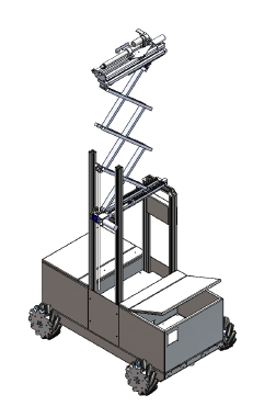 Figure 1: Schematic illustration with meconium wheel drive in the chassis and scissor lift on top.
3. System overview
Figure 1 shows the developed prototype of a robot system for use in the European XFEL. The robot consists of a mobile drive unit in the lower area and an attached scissor lift for special measuring and inspection tasks.
The drive system of the robot was realized with the mecanum technology [9]. Equipped with four Mecanum wheels, an omnidirectional mobility is achieved. The omnidirectional freedom of movement allows the robot to move better in narrower sections of the XFEL tunnel.
The special feature of a mecanum wheel are the 45 degree angle mounted freewheel rollers, which represent the running surface of the wheel. The size and load capacity of the wheel can be selected according to requirements. There are two different Mecanum wheels. These differ in the arrangement of the freewheel rollers. For the drive with four wheels, two wheels of each type are needed. During assembly, it is important that the pivot of the freewheel rollers points towards the vehicle center.
 Figure 2: Three examples for the mechanical drive
(left: forward; middle: sideways; right: turn on the spot). The arrows indicate the direction of rotation of the wheels.
To illustrate the operation of the mecanum drive, figure 2 shows three different motion scenarios. Driving the wheels in different variations gives corresponding movement patterns. These are enabled by the freewheel rollers. Depending on the direction of rotation of the wheels, movement forces are generated. These can be overlaid or partially canceled out. The resultant force gives the direction of movement. Since there is not much room in the tunnel for turning maneuvers or similar, this property is highly important to avoid possible damage.
For measuring the radiation, as already mentioned, a measuring probe is carried along. This should be guided along the linear accelerator during various measuring runs. There are different scenarios here. One of them is to run along horizontally at a certain height. There are also open structures where the height can vary. For measurement along the accelerator, the probe must be variable in height and positioning. In addition, the robot must not exceed a height of 1.70 m to take his parking position in the charging station.
To meet these requirements, a scissor lift was constructed.With the scissor lift it is possible to reach a big stroke although the basic height is low. For this
purpose, three pairs of scissors are used (see figure 1). In order to move the probe horizontally, a platform with a shifting mechanism was set up on top of the scissor lift. This moves the mounted linear actuator up to 30 cm to the outside. The measuring probe is attached to the linear actuator and can thus be moved horizontally by a further 30 cm. To enable the measurement on the irregular structures, a tilt mechanism has been installed. This tilts the platform, mounted on the scissor lift, by up to 30 degrees. The mechanisms are driven by DC gearmotors. For the vertical stroke a spindle-type lifting gear is used to convert the rotary motion of the motor into a lifting movement of the scissor lift. The motor of the displacement mechanism drives a spindle on which a carriage is moved back and forth, depending on the direction of rotation. To move the tilting mechanism, a linear actuator is used.
The robot is a mobile electronic system that is battery powered. Therefore, several charging stations are mounted in the tunnel to charge the battery. Since the robot performs its tasks autonomously, the charging process must also be carried out autonomously. The safety aspect has to be taken into special consideration. Therefore the charging station may only be active when the robot is in the charging station.
In order to ensure safe charging, the two internal contacts of the charging station must be actuated in order to release the charging current at the external charging contacts. For the precise positioning of the robot in the charging station, guide rails were installed on the right and left. These center the robot when driving into the charging station. This ensures that the contacts always lie directly on top of each other.
3.1. Power unit
The power supply of the robot system is realized with a lithium iron phosphate battery (LiFePo4) from the manufacturer ”Super B”. The model ”SB12V100E-ZC” was used[5]. This battery is protected by an external undervoltage protection and was selected due to its high rated capacity of 100 Ah at a nominal voltage of 13.2 V (1320 Wh). The large capacity in relation to the small size and the low weight of the battery is also crucial for the selection of the battery.
The measured current consumption of the entire system is between 15 to 18 A. Thus, the system can be powered up to five hours. That means, that the system can be operated long enough to carry out measuring trips and to get back to a charging station.
3.2. Hardware
The installed IT components are divided as follows:
- Two main computers,
- two single-board computers of the ”Odroid XU4” type with eMMC flash memory,
- one Raspberry Pi 3,
- one router,
- one network switch,
- two control units
- six motor driver and
- several sensors and cameras.
The control of the entire system is based on the two main computers, one of which controls the processes and the other idles. The single-board computers are connected to the actuators and sensors. They are used as an interface to the main computers, process sensor signals, control the actuators and output status messages. The control of the lifting system is realized with the Raspberry Pi 3. Router and network switch are required for internal and external communication. With the sensors and cameras, the environment of the robot is observed.
3.3. Sensors
For the localization there are two 2D laser scanners of the type ”UST-10LX”[6] manufacturer Hokuyo installed. One in front and one in the back of the robot. Within a range of 270 degree and up to a distance of 10 m, the laser scanner records the surroundings in a single line. This data is also used for the orientation of the robot to the tunnel wall and to prevent collisions. If an object is in the route and is less than 2 m away, a warning is issued. If the object is less than 1 m away, the robot stops to cause no damage. In this case, the monitoring center can intervene manually. For this purpose, eight cameras are installed, which allows complete vision all around the robot. In addition to the camera systems for remote monitoring there is a CCD camera for detecting QR codes, which are installed permanently in the XFEL tunnel. The QR codes contain information about the current location and thus serve the absolute localization of the robot system.
In order to monitor the movement speed of the robot, odometry sensors are used. Hall effect sensors are installed, which incrementally record the rotational movement of the motors. This actual value is processed by a controller to adjust the wheel speed. The regulation of the lifting system is carried out according to the same principle.
3.4. Redundancy
With a redundant system a single point of failure should be excluded. Therefore, components such as the main computer are built in duplicate as a master and slave combination. In the event of a fault, the slave can take over the task of the master and restart it. Thus, a total system failure can be avoided and important measurement data will not get lost. If there is a failure of the data transmission, the measured values can be stored on different hard disks and retransmitted later. The redundant design greatly reduces the risk of failure or data loss.
4. Localization
Reliable localization is one of the most important parts of the robot system. On the one hand, it ensures that the measurement results can be correctly assigned and, on the other hand, MARWIN must be able to find its charging station safely. Repeat accuracy also plays a very important role for meaningful measurement results. The localization is based on the measurement data of the laser scanner and on the odometry data of the wheels. The odometry data are determined from the individual speeds of the wheels and from this the resulting motion of the robot.
In general, a distinction is made between global and local localization. The second has already been researched and discussed many times. In local localization, the robot begins by summing the odometry or laser data to determine its current position from the starting position. It estimates its relative position to the start. For absolute positioning, global localization is added. This topic is far more complex, as the robot must be able to record more information about its environment and thus determine an absolute position. At this point, the ”kidnapped robot” problem should also be mentioned [10].
The entire IT hardware of the robot is linux-based and builds on the ”Robot Operating System” (ROS)[7]. The main components of the software framework of ROS are hardware abstraction, message exchange, packet management and software libraries. The system is divided into the actual basic system ROS and a selection of additional packages which extend the basic system by individual capabilities. ROS is published under the BSD license and is thus open-source. How exactly ROS works and is implemented has already been described several times, see e.g. [11, 12, 13].
4.1. Environmental conditions
The total length of the XFEL tunnel is about four kilometers. The robot-assisted radiation measurements are carried out for two sections each one kilometer long. As shown in Figure 3, the tunnel is straight. The robot moves along a corridor about 1.4 m wide along the tunnel. The charging stations described in section 3 are located underneath the beamline. In order to prevent damage to the research facility when entering the charging station, precise positioning is crucial. The robot must not collide with the system in any situation. As shown in Figure 3, QR codes are mounted along the tunnel on a rail at 10-meter intervals. The absolute position is encoded in the QR codes.
Furthermore occurs during operation of the accelerator facility ionizing radiation. This consists mainly of gamma and neutron radiation. Since the robot is used during operation, it can happen that one bit flip over due to radiation, software errors can occur.
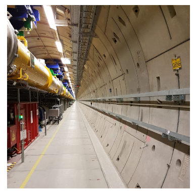 Figure 3: View along the XFEL tunnel
4.2. Solving approaches
It is important for the robot to be able to determine its absolute position in the tunnel because it must travel to exact coordinates for targeted measurements and loading maneuvers. Therefore, global localization is essential. For this reason, a camera was attached to the robot, so QR codes can be scanned by passing. The position information is encoded in the QR code, the edge length is 5 cm, and the average distance between QR code and CCD camera is 120 cm. The image data of the QR camera are read in and converted to a ROS format. The image is then decoded by the ROS package zbar ros. The result is a string that contains the tunnel position.
Since the QR codes are 10 meters apart on average, further localization is required. There are basically two approaches to this:
- Localization without known map (SLAM)
- Localization with known map
So-called ”Simultaneous Localization And Mapping” (SLAM) algorithms work on the principle of adding up the smallest trajectories and thus drawing conclusions about the relative position. There are different sources of information. In the case of MARWIN, a SLAM method was tested and evaluated with the existing sensors.
Likewise, the localization was tested on the basis of an existing map. However, this method requires an already existing as accurate map. These exist theoretically in the blueprints of the XFEL research facility, but there are many details that actually look different (eg mobile pumps, work platforms, smaller implements, tools, etc). For this reason, a map was generated by means of QR codes and SLAM methods. Based on this map a pure map based localization was tested.
4.3. SLAM results
Different ROS packages were used for the SLAM test. During the software research of possible SLAM algorithms, it was found that no software package allows localization correction by external sensors such as the QR camera. The information of the QR codes can therefore not support the localization in the SLAM approach. The condition of supporting laser and odometry data has fulfilled two software packages, gmapping by OpenSlam[8] and hector slam by TU-Darmstadt[9]. Both build on so-called particle filter which has been described in several papers [14, 15, 16]. In the application, they differ in that hector slam also works without odometry data. Furthermore, they differ in the generation of the maps. The software gmapping starts with a freely definable initial map size. When the robot reaches the limits of the initial map, it is extended by another unknown block. The software hector slam is different here. The map size must already be known at the beginning, as well as the map must be square. It is not dynamically expanded during runtime. If the robot reaches one of the map boundaries, it loses itself and the localization fails in this area.
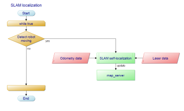 Figure 4: Flow chart of SLAM localization
Figure 4 shows the procedure for the SLAM approach. As the robot moves, this map will be expanded with obstacle information through the SLAM algorithm. The software receives the information from the odometry and laser sensors, weights them and estimates the probable pose.
4.3.1. Using gmapping
First tests with gmapping showed that the laser scanners are not arranged with sufficient accuracy (see figure 5). However, this is not a gmapping error, but a misalignment of the laser sensors. The resulting map clearly shows a curvature that is not present in reality. The XFEL tunnel is straight.
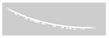 Figure 5: Incorrectly set laser data lead to curvature of the straight tunnel
Then the test was repeated for a distance of 50 meters and the laser data was recorded. In a simulation a correction factor could be determined over several iterations and thus the arrangement of the laser scanners could be corrected by software. When creating maps with an edge length of 1000 meters and more, a limit was detected. It seems like there is a maximum size of the map, which depends on the chosen resolution. It was found that at a resolution of 20 cm per pixel the entire tunnel section (about 1000 m) can be mapped. By increasing the resolution to 10 or 5 cm per pixel, the dynamic map extension stops after some successful expansion. This has the consequence that gmapping is usable in this case only at a maximum resolution of 20 cm per pixel. However, the positioning accuracy is worse than expected. The rough map has the consequence that the robot can not approach its measuring positions exactly. Likewise, a precise retraction into the charging station is not possible.
4.3.2. Using hector slam
As already described, the map size is already defined at program start and is not dynamically expanded during runtime. In addition, the map is necessarily square, since only the edge length of the map can be specified. It has been found that the memory used and the resulting computation cost is significant for a 20000 px square map (1000 m/0.05 m px−1). Therefore the software was adapted and the possibility of a rectangular map implemented. This allowed the map to be reduced to 20000 px length and 200 px width. It also increased performance and reduced processor load.
Our first test purpose was the reproducibility of the measuring points. Therefore, we let MARWIN perform, for three different distances, 20 times the same test drives autonomously. The first given range was 50 m, the second 100 m and finally 200 m. The tests were always starting from the same point at 280m of the XFEL. The distance travelled in real world was compared against the distance the robot was estimating. Finally, the deviation of the position alongside the tunnel was determined. The results are shown in figures 6. It seems that the localization error is increasing with longer traveled distances.
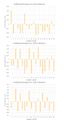 Figure 6: Experimental results of slam test drive (50 to 200 m) using hector slam in the XFEL tunnel
Since the robot has been delivered, the system is constantly being further developed and improved. For a different section in the tunnel (1100 m to 2100 m) a second robot with the same sensor setup was built. Contrary to expectations, however, the position accuracy has deteriorated considerably here. After a distance of 900 m the robot had a positioning error of 9.63 m. Some areas in the second tunnel section lead to positioning problems.
 Figure 7: Area with less obstacles in XFEL lead to localization errors
As shown in figure 7 areas were passed with nearly no objects. Within these areas hector slam had problems for determining the travelled distances. For better results the covariances of odometry data had to be optimized. The covariances give the odometry data a weighting and thus describe a probability of correctness. The procedure of the optimization can be considered in detail in [17]. As a result the error after travelled distance of 900 m could be reduced from 9.63 m to 2.43 m.
4.4. Static map results
The final map of the SLAM tests described above was taken for static map tests. As described, there is an error of 2.43 m after 900 m travelled distance, resulting in an error of 0.27 %. The length of the map has been corrected by this value in order to approximate it linearly to reality.
The software for the static map tests is included in ROS as a software package from the navigation stack, called amcl[10]. As shown in figure 8, it requires sensor input of 2D-LIDAR data, odometry data and a given static map. Optionally, the position estimation can dynamically be set to a given point in the map. In this way, the QR data are used.
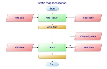 Figure 8: Flow chart of static map localization
Tests for the different distances (50 m, 100 m and 200 m) were repeated as done before in SLAM tests. The results are shown in figure 9. The tolerance in the positioning accuracy is about 5 cm.
4.5. Influence of radiation
Due to the redundant structure of the computer units a failure of a unit can be compensated. However, it has been found that the neutron radiation measurably affects the laser sensors. Depending on the intensity of the radiation, it happens that individual measuring points of the laser scanner are falsified. This expresses itself concretely in the fact that the distance in this point is zero.
Due to the fluctuating radiation conditions in the XFEL, it is difficult to carry out targeted radiation tests and to condition the robot system with defined radiation doses. Nevertheless, initial findings were obtained. For this purpose, MARWIN measured weekly the radiation doses of the accelerator system and the number of falsified measuring points. These data were related to each other (see figure 10). The radiation was recorded at a distance of about 80 cm from the laser scanners.
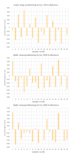 Figure 9: Experimental results of static map test drive (50 to 200 m) in the XFEL tunnel
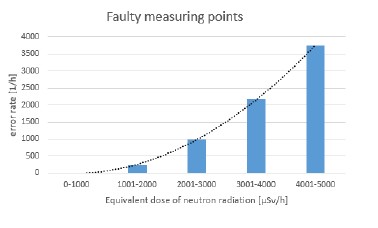 Figure 10: Faulty measurement points for selected groups of neutron radiation doses
5. Conclusions
The SLAM tests have shown that the positioning error increases with the distance traveled. The SLAM approach with hector slam has great results in map sizes up to 200 m. After that, the accumulated errors become larger, so that the localization error becomes too large for the entire tunnel distance of 1000 m and is therefore not sufficient for the requirements of MARWIN. An unconfigurable relationship between map size and resolution in gmapping also leads to insufficient positioning accuracy for MARWIN. In smaller environments, such as the office, these mistakes are not really crucial. However, the accumulation of small localization errors, especially in larger and wide environments, has considerable influence on the positioning accuracy.
The second approach to localization with a static map is a way to move robots in large areas with high positioning accuracy. Due to the positioning tolerance of a maximum of 5 cm, which is related to the resolution of the map, the absolute error is minimal even 1000 m distances traveled. In comparison, the error in the SLAM approach after this distance was 2.43 m.
The combination of creating a map by SLAM method and its linear correction for tunnel-like structures seems to be a good basis for localization methods using static maps.
However, the use of static maps also has the disadvantage that the robot system is no longer able to respond to dynamic changes in the environment. If too many details change in the environment, this can lead to the total loss of localization. This event was detected with tools and mobile equipment left in the XFEL research facility. SLAM approaches are more robust in this scenario.
With the described static map approach the robot system MARWIN is successfully in use. Several times during the operation of the accelerator facility, inspections and autonomous radiation measurements were carried out. For a long-term view of the radiation conditions, a weekly snapshot of the entire research facility is created autonomously by MARWIN.
The influence of neutron radiation on the measurement data of the laser scanner has no noticeable effect on the positioning accuracy. This may be because the number of faulty measurement points per time interval is a fraction of the total number of measurement points. According to the data sheet of the laser scanner used, about 155 million measuring points are recorded per hour, whereas in the dose range of 4001 − 5000 µSv h−1 only about 3700 incorrect measuring points occur. However, should the radiation dose continue to increase, there could be a significant deterioration on the accuracy of localization due to the tendency of the faulty measurement points.
5.1. Further work
The robot system is constantly being improved and developed further. In the specific case of localization, further approaches could be considered. Currently relatively new but very promising is a new approach called Cartographer. This software package is developed by Google and is also based on the SLAM method. Larger environments should be able to be mapped with it [18].
In the long term, further cooperations are to be concluded in order to promote the expansion of other research facilities. It also has a great focus on the development of a manipulator in order to make minor repairs and interventions in the operation of the accelerator system.
- A. Dehne, N. Moller, and T. Hermes, “Marwin: a mobile au-¨tonomous robot for maintenance and inspection in a 4d environment,” in 2017 International Conference on Research and Education in Mechatronics (REM), Sept 2017, pp. 1–5.
- J. H. Zhou, J. Q. Zhou, Y. S. Zheng, and B. Kong, “Research on Path Planning Algorithm of Intelligent Mowing Robot Used in Large Airport Lawn,” in 2016 International Conference on Information System and Artificial Intelligence (ISAI), June 2016, pp. 375–379.
- Y. Zhou, R. Sun, S. Yu, J. Yang, and L. Sun, “An obstacle avoidance method based on non-radial arrangement of distance sensors for vacuum cleaning robot,” in 2016 IEEE International Conference on Robotics and Biomimetics (ROBIO), Dec 2016, pp. 608–612.
- D. Portugal, L. Santos, P. Alvito, J. Dias, G. Samaras, and E. Christodoulou, “SocialRobot: An interactive mobile robot for elderly home care,” in 2015 IEEE/SICE International Symposium on System Integration (SII), Dec 2015, pp. 811–816.
- F. He, Z. Du, X. Liu, and Y. Sun, “Indoor dangerous gas environment detected by mobile robot,” in 2009 IEEE International Conference on Robotics and Biomimetics (ROBIO), Dec 2009, pp. 396–401.
- C.-T. Chiang, “A versatile gas/vision tracking robot for security system applications,” in 2012 IEEE Conference on Control, Systems Industrial Informatics, Sept 2012, pp. 50–53.
- I. Kruij ff-Korbayov, L. Freda, M. Gianni, V. Ntouskos, V. Hlavac, V. Kubelka, E. Zimmermann, E. Zimmermann, H. Surmann, Dulic, Rottner, and E. Gissi, “Ground and aerial robots in earthquake-response in amatrice, italy: a field report,” in Proceedings of the 2016 IEEE International Symposium on Safety, Security and Rescue Robotics (SSSR), Lausanne, Switzerland, October 2016.
- K. Kershaw, F. Chapron, A. Coin, F. Delsaux, T. Feniet, J. L. Grenard, and R. Valbuena, “Remote inspection, measurement and handling for lhc,” in 2007 IEEE Particle Accelerator Conference (PAC), June 2007, pp. 332–334.
- B. I. Erland, “Wheels for a course stable selfpropelling vehicle movable in any desired direction on the ground or some other base,” Patent US3 876 255, 1975.
- I. Bukhori, Z. H. Ismail, and T. Namerikawa, “Detection strategy for kidnapped robot problem in landmark-based map monte carlo localization,” in 2015 IEEE International Symposium on Robotics and Intelligent Sensors (IRIS), Oct 2015, pp. 75–80.
- M. Koseo¨ glu, O. M. C¸elik, and O. Pekta¨ s¸, “Design of an autonomous mobile robot based on ros,” in 2017 International Artificial Intelligence and Data Processing Symposium (IDAP), Sept 2017, pp. 1–5.
- Q. Xu, J. Zhao, C. Zhang, and F. He, “Design and implementation of an ros based autonomous navigation system,” in 2015 IEEE International Conference on Mechatronics and Automation (ICMA), Aug 2015, pp. 2220–2225.
- J. Boren and S. Cousins, “Exponential growth of ros [ros topics],” IEEE Robotics Automation Magazine, vol. 18, no. 1, pp. 19–20, March 2011.
- G. Grisetti, C. Stachniss, and W. Burgard, “Improved techniques for grid mapping with rao-blackwellized particle filters,” IEEE Transactions on Robotics, vol. 23, no. 1, pp. 34–46, Feb 2007.
- G. Grisetti, C. Stachniss, and W. Burgard, “Improving gridbased slam with rao-blackwellized particle filters by adaptive proposals and selective resampling,” in Proceedings of the 2005 IEEE International Conference on Robotics and Automation, April 2005, pp. 2432–2437.
- S. Kohlbrecher, O. von Stryk, J. Meyer, and U. Klingauf, “A flexible and scalable slam system with full 3d motion estimation,” in 2011 IEEE International Symposium on Safety, Security, and Rescue Robotics, Nov 2011, pp. 155–160.
- P. Eberhard and Q. Tang, “Sensor Data Fusion for the Localization and Position Control of One Kind of Omnidirectional Mobile Robots,” in Multibody System Dynamics, Robotics and Control, pp. 45–73, Springer, Vienna, 2013.
- W. Hess, D. Kohler, H. Rapp, and D. Andor, “Real-time loop closure in 2d lidar slam,” in 2016 IEEE International Conference on Robotics and Automation (ICRA), May 2016, pp. 1271–1278.