
Application of Modularization Idea of Fault Tree in Ship Pilotage Risk Decision Making
Volume 3, Issue 4, Page No 341-346, 2018
Author’s Name: Wei Hongbina)
View Affiliations
China waterborne transport research institute, shipping technology research center, 100088, China
a)Author to whom correspondence should be addressed. E-mail: hrbeuweihongbin@163.com
Adv. Sci. Technol. Eng. Syst. J. 3(4), 341-346 (2018); ![]() DOI: 10.25046/aj030434
DOI: 10.25046/aj030434
Keywords: Ship pilotage risk, Dynamic fault trees(DFT), Binary Decision Diagram (BDD), Modular Fault Tree (MFT), Markov models

Export Citations
Ship pilotage risk decision-making problems, which is an important issue affecting the safety of navigation. Before the study on the risk decision of ship pilotage, all use direct analysis of fault tree methods. In this paper, through the process analysis of ship pilotage fault tree, the model of fault tree is standardized and simplified. The traditional method solves the fault tree directly, obtains the ship pilotage risk analysis result, in this paper, use modular decomposition fault tree. Combined with the characteristics of no recurrence events in ship pilotage risk fault tree, the Modular Fault Tree (MFT) method is used to decompose the fault tree into static sub module and dynamic sub module. It solves the fault tree for computation reduction difficulty. Solve static fault tree with Binary Decision Diagram (BDD) method, solve dynamic fault tree with Markov Model Method, and make qualitative and quantitative analysis separately. Then synthesize the result, get the critical path and key event that cause the ship pilotage risk. The results can be used in the design of ship pilotage scheme, post training of ship pilots, or be provided recommendations to ship pilotage and maritime safety authorities for risk reduction.
Received: 27 June 2018, Accepted: 12 August 2018, Published Online: 21 August 2018
1. Introduction
The piloting of ships is an indispensable part of port security and services, an important part of international shipping, and the first image of a country. With the acceleration of the construction and commissioning of a large number of large-scale berths and the acceleration of large-scale ships, the safety of ship piloting has received increasing attention. Pilotage agencies have formulated the “Navigation Pilot Safety Management System” based on their own operations. The safety precautions for ship pilotage must be internally and externally repaired. While building the internal management system of the piloting organization and improving the pilotage technical level, it is necessary to coordinate and master the changes in the external environment and to prevent the occurrence of the piloting safety accident to the greatest extent possible. The study of ship pilotage risk project has important practical significance and has a strong guiding role in preventing the occurrence of ship pilotage accidents. Risk assessment is the quantitative assessment of the degree of impact or loss brought about by an event or thing. A large number of scholars have already conducted research on the risk assessment of ship pilotage.
1.1. Method
In the application of ship pilotage risk methods, In [1], the author used FMEA Method and DFT analysis of ship pilotage risk. In [2], the author used FTA Method analysis of ship pilotage risk. In [3], the author analysis of ship pilotage risk based on the case of ship pilot accident. The researchers used the FTA method to analysis system failures and risks, and propose solutions based on the results for the corresponding risks [4] [5] [6]. In [7], the author used risk matrix and risk criteria. In [8], the researcher used gray comprehensive evaluation model. In [9], the author used the unknown measure model and the confidence identification criterion. In [10], the presenter used the Bayesian method. In [2], the author established a ship pilotage risk analysis model based on the SHELL model, Li Fen use the A.D. Hall models to do the system analysis [11]. The author uses Synergy-based mode to study the management risk of marine traffic [12] [13]. In [1], the researcher proposed model based on A.D. Hall models. However, the study of the module decomposition method applied to the analysis of ship’s piloting risk fault tree is still in the blank.
This paper first simplifies the fault tree construction process. By using the module decomposition method, the complex fault tree is decomposed into independent submodules that can be reduced in dimension, and the appropriate method is used to solve the submodules.
The module decomposition method is used, the top-down or bottom-up combination method is used, MTF method is used to solve the fault-free tree which have no duplicate events. Independent modules can be divided into static modules and dynamic modules. The basic operations of the BDD method are introduced. The BDD method is used to solve the static fault tree module. Through qualitative and quantitative analysis, the cut set of each static submodule is obtained. The Markov model concept is used, which is used to convert DFT to Markov chain, and the cut set of each dynamic sub-module is obtained through analysis. At last individual modules result is synthesized. Comparing the calculation process and results of module decomposition and non-use, the module decomposition method has high usability and high computing efficiency.
2. FTA Construction Process
The fault tree construction process is shown in the figure. It mainly includes analyzing the event background, determining the top event, determining the basic event, establishing the fault tree, and standardizing and simplifying. For detail, see figure 1.
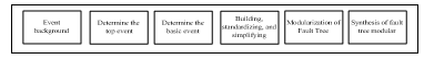 Figure1: Dynamic fault tree construction flow chart
2.1. Event background
Establishing a fault tree first requires a clear structure, condition, purpose, and content. By understanding the background of shipboard piloting risk events and the structure, then environmental conditions of the incidents will be mastered; the impact of subjective and objective factors on the occurrence of the incidents will be identified, the possible transitions between modes and modes of the incidents will be identified, and the failure modes will be identified. Ship pilotage has internal and external risk.
2.2. Determine the top event
A fault tree that meets a variety of different needs is built for different goals. The goals mentioned here are top events. The top event should have a clear definition. When there are many events that are not expected to occur in the system, one or more of the most undesirable events need to be selected as the top event of dynamic fault tree analysis. In the process of establishing the top event, you can use the RPN method to identify the most undesirable events. Collision is as the Ship pilotage risk top event[1].
2.3. Determine the basic event
The basic event is the lowest level cause of the failure of the system, and it is the input parameter of qualitative and quantitative analysis of the system’s risk. The granularity of the basic event directly determines the complexity of the dynamic fault tree. Basic events are usually modules that are not easily split in the system, as well as human factors and environmental factors. In the process of establishing a basic event, you can use the FMEA method to identify the lowest event that affects the top event[1]. The Fault tree of Ship pilotage risk has fifteen basic events.
2.4. Building, standardizing, and simplifying
The general method of building trees is divided into two categories: deductive method and computer-aided tree-building method. The second method is that people input relevant basic events and their relationships and are automatically generated by computer programs. The deductive method is the most commonly used method of dynamic fault tree construction, starting from the top event, from top to bottom, following the step-by-step principle until the lowest row of cause events are bottom events. The resulting graph representing these logical relationships is a dynamic fault tree. The specification and simplification are intended to not change the logical functions that they represent, and try to make the fault tree contain only simple typical logic gates for subsequent fault tree solving. The specification and simplified fault tree can be seen from Appendix figure 8. The Fault tree of Ship pilotage risk has been build, and the event can be seen from Appendix table 3[1].
2.5. Modularization of Fault Tree
For complex large fault trees, due to the large scale of their Markov model, the exact processing of Markov chains is almost impossible. Modular thinking applied to dynamic fault tree analysis. Find out the independent static subtrees and dynamic subtrees in the dynamic fault tree [14]. The Fault tree of Ship pilotage risk is decomposed static subtrees and dynamic subtrees.
2.6. Synthesis of fault tree modular
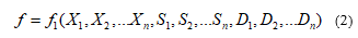
Assume that the bottom event of the dynamic fault tree is, where { } the dynamic fault tree can be expressed as [14] [15]
![]() The dynamic fault tree is preprocessed and modularized, and it contains the static subtrees are, , and the dynamic subtrees are ,then the dynamic fault tree can be written as [14] [15]
The dynamic fault tree is preprocessed and modularized, and it contains the static subtrees are, , and the dynamic subtrees are ,then the dynamic fault tree can be written as [14] [15]
 3. Modularization of Fault Tree
Due to the increase in the complexity of the fault tree, the difficulty of the solution increases during the fault tree computation. Modularity reduces computational complexity. Therefore, we apply the modularization idea to dynamic fault tree analysis to find independent static subtrees and dynamic subtrees in the dynamic fault tree, apply algorithms to the static subtrees, and use the Markov chain for dynamic subtrees. The methods are analyzed separately. Finally, the results of each module are integrated to obtain the results we need. This method is a dynamic fault tree analysis method based on the modular idea.
3.1. The basic idea of MFT method
The MFT method performs depth-first traversal of the fault tree. First, for each intermediate event, decide whether it contains independent modules. If there is a separate module, then it enters the intermediate event traversal, if there is no independent module and the intermediate event itself is independent, the intermediate event is solved using a suitable method according to the characteristics of the module. Then replace the intermediate event with the basic event, and use the failure probability of the intermediate event as the failure probability of the replacement basic event. Then return to the previous point to traverse again. If each independent module under an intermediate event has been solved and replaced with a basic event, continue to check if the intermediate event is an independent module: If so, based on the current module characteristics of the intermediate event, the appropriate method is used to solve the failure probability. Replace the sub-tree with the intermediate event as the top event with a basic event, and repeat until the top event can be solved.
3.2. Specific operation
Uses the MFT method decompose the fault tree module. In the module decomposition process, dynamic subtrees are no longer subdivided when dynamic logic gates are encountered. Applying the MFT method to the fault tree in Appendix figure 8, we first perform a deep traversal from the top event NO.11; because there is an independent subtree under NO.11, the below flag is true. Then entry node NO.11 continues to traverse and the next check is NO.24, which is in the NO.11 leftmost input. Although there are independent subtrees under NO.24, there are dynamic gates under NO.24.For the dynamic subtree with NO.24 as the top event, use the Markov chain model to solve the problem. It is also replaced by a dynamic independent module M1 whose failure probability is the solution value of the Markov chain model. Although there are independent subtrees under NO.24, there are dynamic gates under NO.24.For the dynamic subtree with NO.24 as the top event, use the Markov chain model to solve the problem. It is also replaced by a dynamic independent module M1 whose failure probability is the solution value of the Markov chain model. Therefore, the below flag is set to false, and then NO.23 is converted to the BDD model. And use the BDD solver to solve. According to the traversal result, the fault tree module is {NO.11, M1, M2, M3}, where {M1, M2} is a dynamic submodule, where {M3} is a static submodule and NO.11 is M1, M2, M3 is the static module M4 of the bottom event. Therefore, the fault tree modules M3 and M4 are solved using the BDD method, and the fault tree modules M1 and M2 are solved using the MARKOV chain method.
4. BDD Based Static Fault Tree (SFT) Analysis
The BDD method is an efficient method for analyzing static fault tree (SFT).BDD transforms a fault tree into a BDD map with only the bottom events. Without the aid of intermediate events, BDD Boolean function expressions can be directly used for qualitative analysis and quantitative analysis. The minimum cut set is obtained by the disjoint expression of the Boolean function. The BDD method has a linear relationship with the amount of
BDD graphics. Effectively solve the problem of exponential growth in the computational complexity of the traditional FTA method and the size of the fault tree[14][15].
4.1. Composition method
The basic idea of compositional composition method is “modularization” first. The gate node that has only the bottom event input is represented as a BDD structure. Then regard these gates that have been expressed as BDD as the input of the upper level logic gates. Layer by layer until the top event is expressed by the BDD structure. In the composition method, combination and simplification are based on the following principles. The basic event BDD conversion is relatively simple, as shown in the following figure, the left node is 0, and the right node is 1.for detail see figure 2.
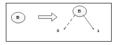 Figure 2: BDD conversion of basic events
For an OR gate in the form of B+C, Assuming B is the top node, C is B left and right nodes. The conversion steps are shown from figure 3.
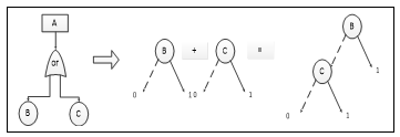 Figure 3: BDD conversion of or door modules
Through qualitative analysis,The cut set of basic events is {B}、{C}.
4.2. Specific operation
The fault tree modules M3 is the static module, for the static module, use BDD method. The conversion steps are shown from figure 4.
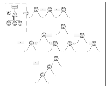 Figure 4: BDD conversion of M3 submodules
Through qualitative analysis,The cut set of basic events is {No.307}、{No.308}、{No.309}.
The fault tree modules M4 is the static module, for the static module, use BDD method. The conversion steps are shown from figure 5.
Through qualitative analysis,The cut set of basic events is {M1}、{M2}、{M3}.
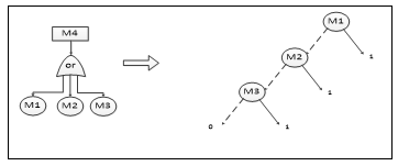 Figure 5: BDD conversion of M4 submodules
5. Markov-based DFT Analysis
The Markov process is a stochastic process. From the current determination of the future behavior of the process, it is the relationship between the “state” and “state” of the system. In a random process, if at a certain moment, the transition probability from one state to another is only related to what state it is now. And it is completely irrelevant to the state it was in before this moment, That is, this transition probability is only related to the current state, and has nothing to do with the state before a finite number of times. This process is called Markov process to analyze the dynamic subtree in the modular fault tree[16][17].
The fault tree modules M1 is the dynamic module, for the dynamic module use Markov model. See figure 6 for detail.
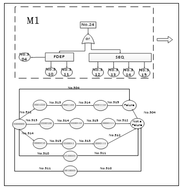 Figure 6: Markov conversion of M1 submodule
Through qualitative analysis The cut set of basic events is
{No.304}、{No.312、No.313、No.314、No.315}.
The fault tree modules M2 is the dynamic module, for the dynamic module use Markov model. See figure 7 for detail.
 Figure 7: Markov conversion of M2 submodule
Through qualitative analysis,The cut set of basic events is {No.305、No.301}、{No.306、No.301}、{No.305、No.302}、{No.306、No.302}、{No.305、No.303}、{No.306、No.303}.
6. Synthesis of fault tree
Based on SFT and DFT Analysis, the fault tree have four submodules, and every submodule has the cut set of basic events.M4 submodule has the top event.
Table 1. The synthesis sequence cut set of fault tree
| The fault tree submodules | The cut set of basic events |
| M1 | {No.304}、{No.312、No.313、No.314、No.315} |
| M2 | {No.305、No.301}、{No.306、No.301}、{No.305、No.302}、{No.306、No.302}、{No.305、No.303}、{No.306、No.303} |
| M3 | {No.307}、{No.308}、{No.309} |
| M4 | {M1}、{M2}、{M3} |
From the above results, we can see that the fault tree have four modules and have 14 sequence cut sets, and there are at least 14 ways to lead to the top fault event.in the 14 sequence cut sets, the least one is {No.304}, which contains the least number from the qualitative analysis, and also is the most important structure of bottom events, which should be strengthen security measures to avoid incidents.
7. Comparisons and analysis
The resolution of a DFT is much different than the one of the SFT, because temporal and cross dependencies cannot be modelled and solved through Boolean algebra [17].In these paper the DFT is converted to Markov chain which can be used to solve the dynamic the sequence cut sets of the fault tree, and the SFT is converted to BDD. Based on SFT and DFT Analysis, the fault tree has four submodules, and the SFT has 3 events.
Table 2. A comparison of the number of dynamic fault tree events
| Direct | After modularization | |
| Number | 15 | 12 |
From the above results, through modularization, the number of dynamic fault tree events is reduced from 15 to 12. The computation of the DFT has been reduced. Because the events of the dynamic fault tree have sequential dependencies, the numerical combination method cannot be used to solve the problem. In general, Markov model is used to solve the problem. However, the number of states involved in the Markov model is exponentially related to the basic events. The number of basic events of the dynamic fault tree is reduced. This reduces the number of states involved in the Markov model. Thus the computational complexity is reduced.
8. Conclusion
Through the analysis of the fault tree construction process, the fault tree analysis model is simplified and the modular idea is adopted. This simplifies the calculation of the fault number.
Modular decomposition results in mutually independent static submodules and dynamic submodules. BDD method is used to decompose the static fault tree, and the dynamic fault tree is decomposed by Markov model method. Then the results are combined. The computational process shows that compared with the modular decomposition of the fault tree, the analysis efficiency are greatly improved.
The fault tree computation solution process is simplified compared to previous studies. When the fault tree is solved, the static fault tree module is first decomposed and processed from the total fault tree, and the original fault tree consisting of 20 events and 8 gates is decomposed into four independent submodules. Two of them are Static fault tree module, 2 are dynamic fault tree modules, 2 static fault tree submodules contain 6 events and 2 gates, and 2 dynamic fault tree submodules contain 15 events and 6 gates. The dynamic module uses the Markov method to calculate the large-scale process. After the modular decomposition, the fault tree uses the Markov method to reduce the number of incidents from 20 to 15 and from 8 to 6 to reduce the computation. The calculation results are the same as those of the previous study, confirming the availability of the module decomposition method.
9. Results & Discussion.
By using a dynamic fault tree analysis method based on modular thinking, the failure tree analysis of ship pilotage risk is carried out, and the use of a new fault tree analysis method is emphasized, which can effectively reduce the dynamic fault tree analysis calculation. The problem of modular decomposition of fault tree is solved, such as the module decomposition of fault tree, the transformation of static subtree, the combination of dynamic fault tree module and static fault tree module. And the concrete application of ship pilotage risk fault tree is given. This paper compares and analyzes the direct solution of fault tree and module to solve the fault tree, and proves the simplicity and practicability of the new method by the practical calculation of the fault tree of ship pilotage risk.
However, a simplified calculation method is used to solve the dynamic fault tree model (FTM) of ship pilotage risk, the application of complex FTM is still very difficult, in the future, a similar and much simpler analysis would be provided.
Conflict of Interest
The authors declare no conflict of interest.
- Wei Hongbin, “DFT analysis of Ship pilotage risk based on A.D. Hall models” in 2017 6th International Conference on Transportation and Traffic Engineering, Hong Kong, China, 2017. https://doi.org/10.1051/matecconf/201712404010
- Xuan Shaoyong, “FSA and Its Application in Ship Pilotage Safety,” MASTER Thesis, Shanghai Maritime University, 2005.
- Xue Yi dong, “Human Errors and Prevention of Accidents in Ship-pilotage,” NAVIGATION OF CHINA, 19(03), 28-32, 2005. http://dx.chinadoi.cn/10.3969/j.issn.1000-4653.2005.03.007
- Lin Tie liang, “Construction of Fault Tree Based on Records of Ship Impact Against Bridges,” JOURNAL OF TONG JI UNIVERSITY(NATURAL SCIENCE), 34(4), 467-471, 2006.http://dx.chinadoi.cn/10.3321/j.issn:0253-74X.2006.04.008.
- Bai Xu, “Process Risk Analysis of Lifting Transportation for Offshore Structure Based on FMEA and FTA,”.SHIP BUILDING OF CHINA,0(4), 171-179. 2012. http://dx.chinadoi.cn/ 10.3969/j.issn.1000-4882.2012.04.022.
- Zhang Qing, “Failure risk analysis on intelligent brakesbased on FMEA and FTA,” CHINESE JOURNAL OF CONSTRUCTION MACHINERY, 14(2), 109-113,2016. http://dx.chinadoi.cn/10.3969/j.issn.1672-5581.2016.02.004.
- FANG Quan-gen. “Application of formal safety assessment to the risk assessment of the ship-pilotage,” Journal of Harbin Engineering University, 27(03), 329-334, 2006. http://dx.chinadoi.cn/10.3969/j.issn.1006-7043.2006.03.003
- Zhou Lili, “Grey assessment model on risk factors of ship pilotage,” Journal of Shanghai Maritime University, 29(02), 21-25, 2008. http://dx.chinadoi.cn/10.3969/j.issn.1672-9498.2008.02.005
- XI Yong-tao, “Preliminary Risk Assessment on Pilotage Water Area Based on Unascertained Measure,” SHIP & OCEAN ENGINEERING, 38(01), 56-58, 2009. http://dx.chinadoi.cn/10.3963/j.issn.1671-7953.2009.01.017
- Fang Cheng, “Risk Prediction of Ship Pilotage in Harbor,” NAVIGATION OF CHINA, 31(04), 388-391, 2008.http://dx.chinadoi.cn/10.3969/j.issn.1000-4653.2008.04.017
- Li Fen, Jichang Ming, Liu Yuan, Kingjian. Research on risk assessment method of a.d.hall system of Water conservancy and hydroelectric project based on analytic hierarchy process [J]. water resources and hydropower engineering,41 (03), 50-52 , 2010.http://dx.chinadoi.cn/ 10.3969/j.issn.1000-0860.2010.03.013
- J Zhang, Q Fang, S Hu. Synergic Mode of Grid-based Traffic Risk Control in China’s Coastal Waters. 2010 IEEE International Conference on Industrial Engineering and Engineering Management, Dec, 2010 .https://doi.org/10.1109/ieem.2010.5674148
- Q Fang, T Xi, S Hu. Synergic mode for marine traffic risk management based on levels and periods synergic modes. Journal of Shanghai Maritime University. 30(3) , 50-55,2009. http://dx.chinadoi.cn/ 10.3969/j.issn.1672-9498.2009.03.012
- Liu dong, Methodologies of Dynamic Fault Tree Analysis, national defense industry press, 2013.
- Liu Wenbin, “Research on Dynamic Fault Tree Analysis Method Based on Modular Idea,” MASTER Thesis, Nanjing University of Science and Technology, 2009.
- Manno, Gabriele, “MatCarloRe: An integrated FT and Monte Carlo Simulink tool for the reliability assessment of dynamic fault tree,” Expert Systems with Applications, 39(01), 10334–10342 , 2012. https://doi.org/10.1016/j.eswa.2011.12.020
- K. Durga Rao, “Dynamic fault tree analysis using Monte Carlo simulation in probabilistic safety assessment,” E Reliability Engineering and System Safety, 94(01), 872–883 , 2009. https://doi.org/10.1016/j.ress.2008.09.007