
A modular design process for developing humanoid mobile robot VieBot
Volume 3, Issue 4, Page No 230-235, 2018
Author’s Name: Hung Chan Nguyen1, Ha Xuan Nguyen2, Ngoc-Anh Maia,3), Lam Bao Dang2, and Hai Minh Pham2
View Affiliations
1CMC Institute of Science and Technology, Duy Tan str. 11, Hanoi, Vietnam
2Hanoi University of Science and Technology, Dai Co Viet str. 1, Hanoi, Vietnam
3Le Quy Don Technical University, Hoang Quoc Viet str. 236, Hanoi, Vietnam
a)Author to whom correspondence should be addressed. E-mail: maingocanh.atc@mta.edu.vn
Adv. Sci. Technol. Eng. Syst. J. 3(4), 230-235 (2018); ![]() DOI: 10.25046/aj030422
DOI: 10.25046/aj030422
Keywords: Modular design process, Humanoid mobile robot, VieBot

Export Citations
This paper introduces a design process for developing a humanoid mobile robot, namely VieBot. Stemming from the design process, it is easy to adjust the design and extent robot behaviors to meet customer needs. Our key solution is to split the design into three modules related to robot behavior, kinematic computation and motion control. Base on the results from testbed module under comprehensive testing, the design is gradually improved to satisfy sophisticated requirement of assisting disabled people.
Received: 14 June 2018, Accepted: 30 July 2018, Published Online: 05 August 2018
1. Introduction
This paper is an extension of work originally presented in the 2017 IEEE International Conference on Robotics and Biomimetics (ROBIO 2107) [1], which introduced the performance evaluation of a humanoid mobile robot, namely VieBot, using MS Kinect. This paper focuses on a modular design process for developing VieBot.
VieBot is a humanoid mobile robot shaped like a woman (see Figure 1) with some basic components including a head, neck, torso and two arms. It has a vision ability to observe the working environment and to avoid collision via sensor devices working as human senses such as listening, seeing and touching. Its vision ability is based on a Kinect.
Kinect camera is a sensor device using depth and RGB camera images to support robots an outstanding capability to identify human gestures and motions. According to [2], the second generation of the Microsoft Kinect for Windows V2 is based on the Time-of-Flight (ToF) principle and offers a higher resolution and a wider field of view. Based on the properties of high-definition, low-cost image reproduction, this device is often chosen for observing and imitating human behavior and gestures. This device supports many robots in imitating human behaviors in real time or in the recorded data.
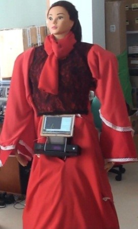 Figure 1:. VieBot’s appearance
The kinect images are processed to regenerate the human skeletal structure. Stemming from the regenerated skeletal structure, the robot control system calculates the poses of robot’s joints and links by means of inverse kinematic expressions and then controls motions of robot’s arm and hand. Based on these flexible motions, VieBot is able to carry out many sophisticated tasks by mimicing complex human behaviors such as greeting, guiding, talking, etc. For this reason, VieBot has been applied for several supportive activities similar to other robots in the world such as guiding visual impaired men [3], assistance robots in hospitals [4], or advertising for clients [5].
According to [6], modular design is aim to select the best assembly of modules for a given task in a design space. The approach of modular design allows a sufficient, cost-effective and rapid design for different specific tasks. For more details, the modular design process is proposed by a hierarchical approach with three levels of filters, simulations, and tests. In our research, a modular design process is modified from [6] by using parallel sub-modules instead of hierarchical sub-modules. The parallel sub-modules concern the designs of robot’s behaviors, kinematic computation for controlling arms and hands, and motion control for travelling.
As stated in [7], behavior-based robot control provides good capabilities to design complex behaviors for robots. The key idea of behavior-based control is a divergence design of a complex behavior by multiple easier designs. This key idea is adopted for building a design module of VieBot’s behavior definition.
To control VieBot’s arms and hands, a design module is created for computing direct and inverse kinematics. The more flexible the arm and hand are, the more complicated the inverse kinematic problem becomes. The most popular solutions for dealing with the inverse kinematic problems concerning three following methods: interactive method [8, 9], geometric method [10, 11, 12] and inverse-transformation method [13, 14]. In this research, the mechanical structure and joint variable constraints of VieBot are applied for controlling the arms and hands based on the method of inverse kinematic computation presented in [14] with a modification of the extensional constraints on joint variables corresponding to the specific mechanical design of VieBot. The movements of VieBot’s arms and hands are controlled based on the result of processing images taken from the MS Kinect V2. The data of Kinect image processing is also used for choosing a suitable solution among multiple ones. The more details of the modification are analyzed in [1].
To travel around surrounding environment, a design module is necessary for motion control. VieBot moves as a mobile robot on a chassis with three wheels. According to [15], static stability requires a minimum of three wheels, with the additional condition that the center of gravity must be contained within the triangle formed by the ground contact points of the wheels. Besides the localization, the path planning is also important to guide the robot moving to a desired target. According to [16], the path planning problem is divided hierarchically into two problems: global path planning and local path planning. In our research, VieBot deals with the second problem based on a Kinect camera and some sonar sensors to easily move to a human target and quickly change direction to avoid obstacles.
In the next section, the modular design process of VieBot is presented with the modules concerning behavior definition, kinematic computation, and motion control. After that, the experiments in a lab environment and in a meeting hall are implemented with regarding specific design modules and evaluating the whole system operation. Finally, the conclusion and future orientation is given.
2. Modular Design Process
The design process for developing VieBot is depicted in Figure 2. It is organized with six modules including CN, BD, KC, MC, DA, and TE.
Module CN contains customer needs such as functionalities, technical requirements, term of service, workplace features. Some other customer needs will be not mentioned such as, time, price, hair color, type of dress.
Module BD defines the basic behaviors based on the existing behaviors designed for VietBot. After defining, these behaviors are sent to the next module for computing kinematics. In case a basic behavior has not defined before, a new definition will be carried out in a sub-module and added to module BD. In fact, the behaviors may be sorted in order of priority. This modular organization allows easy creating of new behaviors.
Module KC provides general direct and inverse kinematic equations for the arms and hands. These equations are supported with technical requirements to form activities matching the identified behaviors. In case there are many solutions due to inverse kinematics, the system must select the best one. The method to select the best solution was described in our other publication [1].
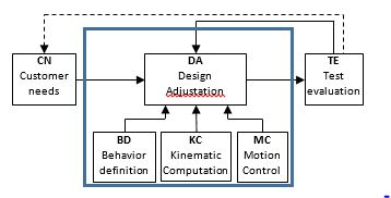 Figure 2: Modular design process for developing VieBot
Module MC provides functions of motion control such as obstacle avoidance and approaching human target. The motion control is computed based on the sensor data and it is constrained by given workplace properties.
Module DA carries out a mechanical design adjustation concerning behavior definition, kinematic computation and motion control for VieBot concerning prioritized behaviors to meet well the customer need. This module provides a concept-to-launch process including modification and refinement.
Module TE performs tests for evaluating the whole design adjustations. Some errors will be detected in this module. Then it feeds back the test results to module DA to ensure the final design meets customer functional or non-functional requirements, and detailed specifications.
It should be noticed that customer needs directly affect module DA in design. The design is refined by cross-checking between the module TE output and the customer needs. If any changes are required, the adjustments are performed again in module DA. This iterative procedure of improvement between TE and DA is performed until satisfying the customer needs.
3. Behavior definition
In this design module, robot behavior definition is a mapping of gestures of human arms and hands to positions and angles of robot’s arms and hands as shown in Figure 3.
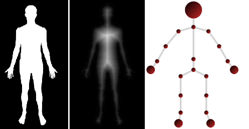 Figure 3: Definition of behavior
Based on customer needs and the behavioral design, the mechanical design inside DA is accomplished to help align the joints and links of the skeleton. For example, a greeting behavior is defined by imitating a human gesture for welcoming by raising hand and waving hand as shown Figure 4. This behavior is designed in module BD with the length of links and joint angles between shoulders, upper arms, elbows, forearms, and wrists. After that, the data of the behavior definition are provided for module DA to design feasible mechanical parts of the arms and their constraints in joint and operational spaces.
 Figure 4: Definition of greeting behavior (Left: human, right: Robot mimicking human)
By the similar way, different behaviors are defined to meet the customer needs. Actually, some behavior definition contains a multi-solution, e.g. left hand or right hand, upper elbow or below elbow, palm of hand or back of hand. In these cases, an additional condition must be included to limit number of solutions.
More details of modular system diagram of behavior-based control can be seen in [16].
4. Kinematic Computation
The design of kinematic computation is carried out in module KC. The kinematic structure of VieBot concerning the arms and hands are shown in Figure 5. The arm has six degree of freedom (DoF) corresponding to the six joints involving the shoulder, elbow, upper arm, forearm and wrist. Furthermore, VieBot has one DoF for controlling the five-finger hand to open and close.
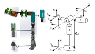 Figure 5: Kinematic structure of VieBot’s arm and hand
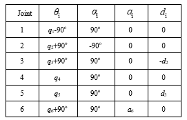 Figure 6: Table of Denavit-Hartenberg parameters of VieBot’s arm
The kinematic parameters of VieBot’s arm is expressed by Denavit – Hartenberg table shown in Figure 6. The kinematic parameters are symbolized as follows:
- θi : angle between axes x(i-1) and xi about axis z(i-1).
- αi : angle between axes z(i-1) and zi about axis xi.
- ai : length between O(i-1) and Oi along xi.
- di : length between O(i-1) and Oi along z(i-1).
- q1, q2, q3, q4, q5, q6 are angular rotation of respective joints in VieBot’s hand.
The kinematic relationship between the shoulder and the hand (considered as the end-effector) is represented by the following equations:
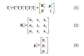 where are transformation matrix, orientation matrix, and position matrix of the hand in comparison with the shoulder; Symbols nx, ny, nz, sx, sy, sz, ax, ay, az stand for rotation vectors of a frame attached to the hand; Symbols px, py, pz express position vectors of the hand.
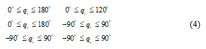
Due to the real mechanical structure of the arm and anthropomorphic motion, the joint variables are constrained to
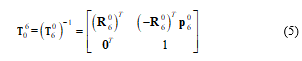
 The inverse kinematic equation has the following form:
 The details of the kinematic computation are written in [1].
This module supports the kinematic computations which are used with the behavior definitions and technical requirements.
5. Motion Control
The design of motion control is performed in module MC concerning avoiding obstacle and planning path. The principle diagram of VieBot’s motion control is shown in Figure 7. This diagram is built based on the generic system architecture for robot control in [7] with four functional modules: Sensor-based Localization – SL, Obstacle Avoidance – OA, Target Approaching – TA and Motion Fusion – MF.
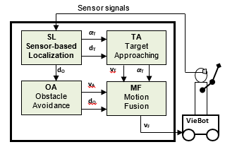 Figure 7: Generic diagram of motion control
Module SL carries out sensor-based signal processing to determine the position and direction of VieBot, human objects and obstacles from the sensors such as Kinect camera and sonar sensors. The outputs of module SL are distance of obstacle, distance and angle of a human target closest to VieBot.
Module TA processes information concerning target distance , and target angle to reckon behaviors for approaching the human target. Module TA provides a velocity command to control the robot approach the human target. It provides a target angle for collaborating motion later.
Module OA calculates behaviors for avoiding obstacles on the way to the target. Module OA give out a velocity command vA for driving the robot safely and the obstacle distance dO for collaborating motion later.
Module MF performs a coordination between the behaviors of approaching target and avoiding obstacle to compute a final velocity command to control VieBot to the target without any collision.
The motion coordination has the following form:
![]() where and are functional factors changed after the target angle from module TA and the obstacle distance dO from module OA.
where and are functional factors changed after the target angle from module TA and the obstacle distance dO from module OA.
6. Experiments and results
VieBot looks similar to a woman with a height of 1.6 meters and a weight of 55kg. Its computer-based brain is built on an Intel Core i7 Mini-PC with 16GB RAM running MS Windows 10. VieBot’s data base of robot is connected with MS Azure cloud through 4G LTE mobile network to use advanced Microsoft Azure cloud services including Face API, Computer Vision and Machine learning that support VIEBOT to recognize human face, gender, age and surrounding objects.
6.1. The experiment objective
The experiments are designed to evaluate VieBot’s modular designs related to defining robot behaviors based on imitating human behaviors, computing kinematics for arms and hands, controlling its motion for travelling around and approaching a human, performing sophisticated tasks involving making conversation and helping an visual impaired man.
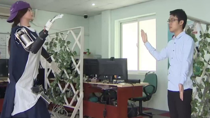 Figure 8: Experiment setup
VieBot communicates with people in the experimental area as illustrated in Figure 8. While Viebot mimicking human gesture, a second Kinect Camera is used to analyze Viebot gestures. Then, two data streams from Viebot Kinect and the second Kinect is compared and processed to calculate errors using MS Excel and some statistical tools.
6.2. Experiment implementation
We did the following three groups of experiments :
GR1: Test the design of human-mimiced behaviors and kinematic computation.
GR2: Test the design of motion control for avoiding obstacle and approaching a human target.
GR3: Performance of sophisticated tasks for helping visual impaired people travel around.
In experiments GR1, VieBot has to mimic some human gestures such as raising and stretching the arm and hand. Its joint parameters are measured and collected to evaluate the accuracy of the design concerning kinematic computation.
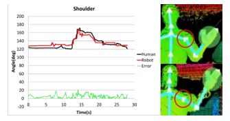 Figure 9: Deviation of VieBot’s shoulder joint compared to the human one
The measured differences of the human and robot raising hand behaviors are shown in Figure 9 for the shoulder joint, in Figure 10 for the elbow joint and in Figure 11 for the wrist joint. The black line demonstrates the human movement, the red one illustrates the robot movement, and the green one is the error between the black and red lines.
Base on the analysis, the mean errors of the joint angles concerning shoulder, elbow, and wrist are computed at 4.32%, 5.73% and 3.12%, respectively. These data demonstrate the effectiveness of design taken on the perceived angles of 51 data points.
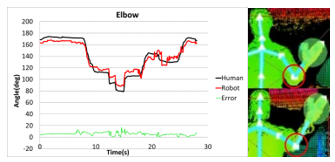 Figure 10: Deviation of VieBot’s elbow joint compared to the human one
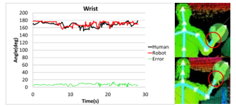 Figure 11: Deviation of VieBot’s wrist joint compared to the human one
Figure 12 demonstrates the dependency of the deviations on the magnitude of joint angles. The results show three error trends of the shoulder (blue), elbow (red) and wrist (green). It is noticeable that the trends depend on the joints differently. In other words, the wrist joint errors depend on the input angles much stronger than the others; the shoulder joint errors weakly depend on the input angles; the wrist joint errors strongly depend on the input angles in the range from 150 to 180 degree. These errors are necessary for the design modification in module DA. Bases on them, the design in DA module can be improved by either way: 1) improve the design of mechanical parts or 2) add automatic offset mechanism into the design of kinematic computation inside sub-module KC to be aware of input angle ranges or 3) refine the behavior design inside sub-module BD.
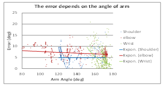 Figure 12: Dependency of deviations on the magnitude of the joint angles
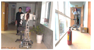 Figure 13: Approaching a human target and avoiding obstacles
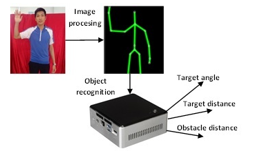 Figure 14: Principle from human recognition to motion control
In experiments GR2, the design of motion control is evaluated by testing the motion of approaching a human target and avoiding some obstacles randomly arranged along the corridor shown in Figure 13. The corridor width is less than 2m and the distance between the obstacles is less than 1.8m. The robot avoids the obstacles with the closest distance of over 15cm and approaches the human target with a distance of about 60cm.
The data of human and obstacle recognition used for motion control is illustrated in Figure 14. The images and depth streams taken from the MS Kinect v2 are processed in a computer Intel NUC. The image processing concerns image enhancement, color processing, segmentation, representation, and object recognition. Stemming from object recognition, the computer extracts object information concerning target angle , target distance , and obstacle distance . These parameters are used for motion control mentioned above in Figure 7.
The experiment results prove that VieBot’s mechanical design under the motion control design can help the robot approach a human target safely without collision with obstacle and maintain a safe distance to the human. If any additional behavior is required, it can be added and adjusted inside sub-module BD to satisfy safety requirements.
In experiments GR3, VieBot carried out some sophisticated tasks concerning helping a visual impaired man reach a given position as shown in Figure 15. Firstly, VieBot approached a visual impaired man in a safe distance approximately 60cm, raised its hand toward the man and asked him to give his hand forward and take its hand. Then, VieBot observed the furniture obstacles on the way to plan a path for safely moving and led him to the given position.
 Figure 15: VieBot is guiding a visual impaired man to his desired position.
While guiding the visual impaired man, since the furniture in the room is considered as obstacles, the behavior of avoiding obstacles is always activated beside the leading behavior. The test results demonstrate the ability to coordinate the design for complex missions.
7. Conclusion
This paper presents the modular design process of VieBot, a humanoid mobile robot developed in Vietnam. The novel design approach facilitates easy extension of new behaviors as well as improve robot performance and precision both robot arm and movement control.
Three groups of experiment in real-world conditions show the advantage of this modular design approach in quickly satisfying user requirements and improving robot performance in sophisticated activities such as assisting visual impaired people.
In further research, more collaborative scenarios will be studied such as access elevator, assisting disabled people in the variety of environments both indoor and outdoor.
Conflict of Interest
The authors declare no conflict of interest.
Acknowledgment
The authors express their high appreciation for the World Bank project FIRST (Fostering Innovation through Research, Science and Technology) for the financial supports.
- H. X. Nguyen, H. C. Hung, N. A. Mai, H. T. Nguyen, D. X. Tran, L. D. Dang, H. M. Pham and L. N. Dinh, “Performance evaluation of an inverse kinematic based control system of a humanoid robot arm using MS Kinect”, in IEEE ternational conference on Robotics and Biomimetics (ROBIO), 2017, pp. 469-474.
- P. Fankhauser, M. Bloesch, D. Rodriguez, R. Kaestner, M. Hutter, and R. Siegwart, “Kinect v2 for mobile robot navigation: evaluatiion and modeling”, in International Conference on Advanced Robotics (ICAR), 2015, DOI: 10.1109/ICAR.2015.7251485.
- T. C. Pham, “Robotic research trends in the world and robotic research and development in Vietnam”, in Journal of Computer Science and Cybernetics, Vol. 26, No. 3, 2010, pp. 197-212.
- T. S. Dahl and M. N. K. Boulos, “Robots in Health and Social Care: A complementary Technology to home care and telehealthcare?”, in Journal of Robotics, Vol. 3, 2013, ISSN 2218-6581, pp. 1 – 21.
- P. Kucsera, “Autonomous advertising mobile robot for exhibitions, developed at BMF, Towards Intelligent Engineering and Information Tech. SCI 1243, 2009, pp. 295 -303.
- S. Farritor and S. Dubowsky, “On modular design of field robotic systems”, Autonomous Robots 10, 2001, pp. 57-65
- N. A. Mai and K. Janschek, “Generic system architecture for behavior-based mobile robot control using fuzzy logic”, in International Conference on Control, Automation and Information Sciences (ICCAIS), 2012, pp. 253-258.
- Riadh Zaier, “The Future of Humanoid Robots – Research and Applications”, Text book, ISBN 978-953-307-951-6, 310 pages, Publisher: InTech, 2012. (Edited Volume)
- R. Arnay, H. A. Javier, G. Evelio, and L. Acosta, “Teaching kinematics with interactive schematics and 3D models”, in Computer Applications in Engineering Education, vol. 25, Iss. 3, 2017, pp. 420-429.
- K. Tokarz and S. Kieltyka “Geometric approach to inverse kinematics for arm manipulator”, in Journal of latest trends on systems, vol. II, ISSN 1792-4235, ISBN 978-960-474-214-1, pp. 682 – 687
- G. Tevatia and S. Schaal, “Inverse kinematics for humanoid robots,” in Proc. IEEE International Conference on Robotics and Automation (ICRA), vol. 1, 2000, pp. 294–299.
- J. Wang and Y. Li, “Inverse kinematics analysis for the arm of a mobile humanoid robot based on the closed-loop algorithm,” in Proc. of the IEEE Information and Automation (ICIA), 2009, pp. 516–521.
- T. Asfour and R. Dillmann, “Human-like motion of a humanoid robot arm based on a closed-form solution of the inverse kinematics problem”, in Proceeding of the IEEE/RSJ International Conference on Intelligent Robots and Systems (IROS 2003), 2003.
- J. I. Zannatha and R. C. Limon, “Forward and inverse kinematics for a small-sized humanoid robot,” in Proc. of the IEEE Intl. Conf. on Electrical, Communications, and Computers, 2009, pp. 111–118.
- K. Goris, “Autonomous Mobile Robot Mechanical Design”, Report, Vrije Universiteit Brussel, 2005, p. 19.
- N. A. Mai, Optical flow-based perception, behavior-based control, and topological path planning for mobile robot using fuzzy logic concepts, TUDpress, 2012.