Dc-link voltage drift compensation in a four level Double- Star Converter using redundant states via phase-shifted PWM strategy

Adv. Sci. Technol. Eng. Syst. J. 3(4), 53–58 (2018);
 DOI: 10.25046/aj030407
The following work introduces the use of the available Redundant switching states introduced by the double star four level converter topology, for its application in a medium voltage variable speed drive under a wide range of operation loads. Redundant switching states are obtained using multi-carrier phase-shifted pulse width modulation (PWM) strategy. The converter performance is evaluated in terms of the dc-voltage drift and the torque ripple on the load side, when compared with a classical level-shifted PWM modulation.
1. Introduction
Modern industrial high demanding processes are commonly based on medium voltage induction machines (MV-IM) AC-drives with Field Oriented Control (FOC) scheme [1]. In this field of applications, voltage source multi-level converters are the dominant topologies used in industry, rather than two-level voltage source converters (2L-VSC), in order to reduce the blocking voltage rating of power switches (semi-conductors) as well as conduction losses; harmonic distortion is also minimized ensuring a low rate of torque ripple [2].
Commonly adopted converter topologies for industrial applications are based on cascade H-Bridge (CHB), neutral point clamped (NPC) and flying capacitor (FC) converters [3, 4, 5, 6]. This configurations can be considered as the today‘s industry standard, because they have reached heir technological maturity proven during the past couple of decades in high demanding industrial processes. However, due the fact that variable speed drives operate within a wide range load profile, most of the time at a fraction of their nominal load, multi-level converters have to deal with this fact, operating in their low modulation index region.
Nowadays, level-shifted PWM (LS-PWM) strategy has become a standard as modulation strategy for multi-level converters. However this modulation technique has a poor performance at low modulation indexes, resulting in dc-link voltage unbalance and the consequent torque ripple in the mechanical drive [7].
The recent diversification of the power electronics market, has open a new scenario for medium voltage converter topologies that can compete with today‘s industrial standards, improving the disadvantages of classical converter topologies and keeping their advantages (medium voltage capability, low Total Harmonic Distortion (THD) and low semi-conductor stress) [8].
Following this motivation, in this work a double star four level medium voltage converter topology [9] is introduced for its application in medium-voltage ACdrives. However the topology offers many advantages over commonly used industrial standards, it shows the same problem introduced by level-shifted PWM at low modulation index, as reported in [9].
The main contribution of the of the present work, is referred to the use of the redundant switching states available in the double star topology, to deal with the dc-link voltage unbalance, in low modulation index operation. Redundant switching states are synthesized using a phase-shifted PWM (PS-PWM) scheme. The performance of the proposed solution, is analysed via simulation results using an induction machine Filed Oriented Control drive as industrial load.
2. Double Star Multi-level Converter Topology
The double-star converter (DSC) topology is based on a three-level NPC (3L-NPC) configuration, but with the absence of clamping diodes or switches (as in the case of the ANPC) [9]. The converter front-end is arranged with an 18-pulse diode rectifier, fed from the main grid via a multi-winding zig-zag phase-shifting transformer so that a shifting in -20, 0 and 20 degrees, is achieved. Each diode rectifier is connected to a dc-link capacitor
(each level) and are also interconnected in series to each other as presented in Fig. 1.
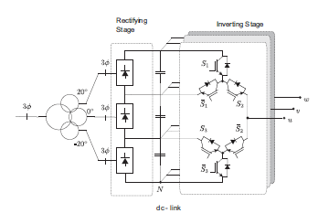 Figure 1: Double Star converter topology
The most remarkable features of this topology are:
- 6 active switches per phase like the three-level Active Neutral Point Clamped converter (3LANPC).
- 4 voltage levels; one more than the 3L-ANPC and using less number of active switches.
- no need of clamping diodes or switches (ANPC and NPC topologies), isolated DC-sources (Cascaded H-bridge CHB) or flying capacitors.
The absence of clamping devices makes that each capacitor is in a floating condition, respect to ground, such as in a three level Flying Capacitor converter (3LFC). The converter fundamental cell (per leg) is presented in Fig. 2 and its corresponding allowed switching states are listed in Table 1
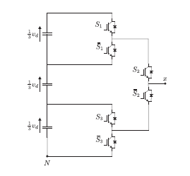 Figure 2: Fundamental converter cell
Table 1: Switch stages per leg (fundamental cell)
| # | S1 | S2 | S3 | vxN |
| 1 | 0 | 0 | 0 | 0 |
| 2 | 0 | 0 | 1 | 1vd
3 |
| 3 | 0 | 1 | 0 | 2vd
3 |
| 4 | 0 | 1 | 1 | 2vd
3 |
| 5 | 1 | 0 | 0 | 0 |
| 6 | 1 | 0 | 1 | 1vd
3 |
| 7 | 1 | 1 | 0 | vd |
| 8 | 1 | 1 | 1 | vd |
Pulse width modulation techniques for multi-level converters, such as level-shifted PWM (LS-PWM) and phase-shifted PWM (PS-PWM), are based on the use of multiple carriers, as an extension of two-level PWM methods. Level-shifted PWM (LS-PWM) strategy has become a very popular multi-level modulation technique, because it is suitable for any multi-level converter topology and presents low harmonic distortion [10, 11]. The corresponding output voltage is synthesized as given in eqs. (1) – (5)
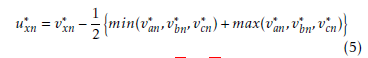
 where stands for the voltage reference corresponding to the x phase, and uc1, uc2, uc3 for the corresponding level-shifted carriers. Each PWM voltage reference corresponds to a min-max optimization strategy, which ensures improvement of the corresponding duty cycles, thus reaching the maximum possible modulation index by including the effect of common mode voltage, as presented in eq. (5)
 As presented in eqs. (1) – (4) using the LS-PWM scheme only switching states 1, 2, 4, 8 are synthesized, neglecting the extra degrees of freedom that offers the converter topology with the redundant switching states, presented in Table 1. When low modulation index operation is required (for the proposed topology m ≤ 0.33), because only the lowest voltage levels are being synthesized, a voltage unbalance in the dc-link starts to build-up, thus requiring the implementation of an additional dc-link voltage balance strategy, as reported in [9, 12, 13].
To deal with the previous described problem, the double star converter extra degrees of freedom can be exploited by implementing a PS-PWM modulation scheme, thus introducing a phase-shifting for the kth carrier denoted by θk and given in eq. (6)
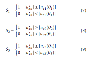
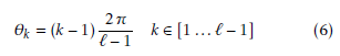 where ` represents the number of voltage levels of the converter. All available switching states shown in Table 1 are then used. Redundant switching states are synthesized, according to eq. (5), (7) – (9), introducing redundant switching states to those allowed in the LS-PWM scheme.
 PS-PWM scheme ensures that each capacitor will be delivering energy at its corresponding duty cycle, independently of the modulation index, thus reducing the natural voltage unbalance, without the need of an external voltage drift control scheme.
It also has to be noted, that for this particular application in a medium voltage AC-drive, using field oriented control scheme, the modulation strategy has to deal with the dc-link voltage unbalance, without the use of a voltage-drift control, thus the converter voltage references are set by the FOC control scheme, as a function of speed (within a certain load) and flux.
3. Induction machine Field Oriented Control drive
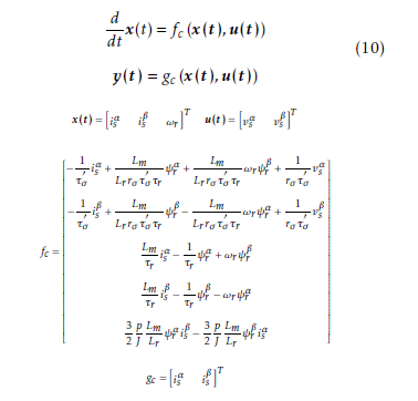
Squirrel cage induction machines (SCIM) are widely used in heavy industrial environments and applications. The three-phase SCIM mathematical model in the natural stator reference frame αβ in state variables
 Control goals for the induction motor drive can be summarize as the following:
- Maximum torque per Ampere operation.
- Control of nominal flux.
- Control of rotor speed.
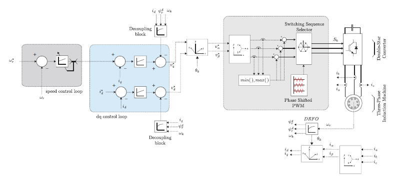 Figure 3: Field Oriented Control scheme with non-linearities compensation
The characteristics of FOC, have made this control strategy the most widely used for high demanding industrial applications [11]. Field Oriented Control (FOC) is based in the decoupling of the current space vector into a flux producing current and a torque producing current [14]. This is achieved by rotating the αβ current space vector is into a synchronous rotating reference frame dq, which is oriented by the rotor flux linkage space vector. Rotation of the state variables is achieved by means of the rotation matrix U given in eq. (11)
 The dynamics in the dq synchronous reference frame are obtained by applying eq. (11) to eq. (10)
(dq) (dq)
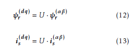
. State variables ψr is can then be obtained as in (12), (13).
 The implementation of the IM FOC control scheme is shown in Fig. 3. Compensation of non-linearities was achieved by including feed-forward compensation for the dq control loop PI controllers.
4. Simulation Results
Dc-link voltage stability performance simulation results, for the double-star converter, are presented for an industrial application consisting in a field oriented controlled induction machine industrial drive, under variable load and speed conditions.
Constant load and variable speed operation results are presented in Fig. 4. Simulations include the initial system speed start-up from 0 to 0.5 [pu] of rated speed in O1 and a speed step-up from 0.5 to 1.0 [pu] of rated speed in O2 under a linear torque characteristic such as TL = kωr
As shown in Fig. 4, during the speed start-up at O1 using LS-PWM strategy the Upper and Middle capacitor voltages raise, because of the floating condition of ground, meanwhile the Lower capacitor voltage drops due the fact that only the lowest voltage level is being used and all energy is drawn only from this capacitor. On the other hand, when implementing PS-PWM scheme, there is no voltage drift. During the speed step-up at O2 implementing LS-PWM the initial observed voltage drift increases, symmetrical from each other. With PS-PWM there is a natural voltage drop in all levels with a small voltage drift but only in the Lower capacitor.
Results for variable load and constant speed operation are shown in Fig. 5. They include the performance
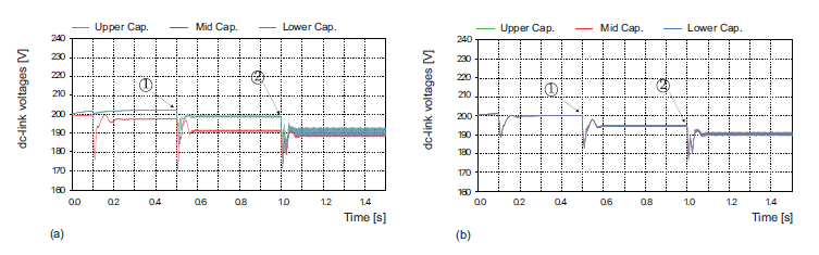 Figure 4: Simulation results for constant load-variable speed operation: (a) dc-link voltages using LS-PWM modulation (b) dc-link voltages using PS-PWM modulation
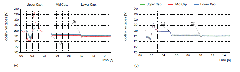 Figure 5: Simulation results for load impact under constant speed operation: (a) dc-link voltages using LS-PWM modulation (b) dc-link voltages using PS-PWM modulation
of dc-link capacitors voltages and the line – line output voltage, for the following operational conditions: initial speed-up transient under no-load condition, a first load impact of 0.6 [pu] at O1 and a second load impact of 1.0 [pu] of rated load at instant O2
An evaluation of the actual benefits of PS-PWM strategy for this particular application in the DSC, can be made by comparing the capacitors dc-voltage drift and the output current THD, for both LS-PWM and PS-PWM strategies. These results are shown in Fig. 6 and in Fig. 7 respectively.
 Figure 6: Total dc voltage drift: (a) constant load variable speed (b) constant speed – variable load
The dc-link voltage drift is shown, for variable speed, constant load operation shown in Fig. 6 (a) and in constant speed, variable load operation as presented in Fig. 6 (b); in both cases, PS-PWM generates a lower voltage drift as with LS-PWM (it has to be noted that no voltage-drift control is implemented).
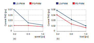 Figure 7: Line current Total Harmonic Distortion
(THD), in per unit [pu] (a) constant load – variable speed (b) lconstant speed – variable load
In Figs.7 (a) and (b) the output currents THD performance is shown, for constant speed and constant load operation conditions, using both, LS-PWM and PS-PWM strategies. On each case the PS-PWM strategy presents a lower THD index.
The harmonic content of the output currents, has a directly impact on the electrical torque developed by the induction machine, due the fact that the electromechanical torque is a function of the stator currents and the rotor flux linkage space vectors.
In Fig. 8 the results for the id iq current control loop, and the developed torque performance are presented. As shown in Fig. 8 (a) and (d) the id iq current control loop (inner control loop) exhibits a good performance either using level shifted or phase shifted PWM. However, results for the electromechanical torque developed by the induction machine, when using LS-PWM strategy, shown in Fig. 8 (b) and (c), exhibit a more scattered harmonic pattern, with higher order frequency components, compared to the results obtained with the PS-PWM strategy, discussed previously.
As shown in Fig. 4 and Fig. 5 PS-PWM modulation strategy offers a better performance during the initial speed-up transition (low modulation index operation region), in terms of dc-link undershoot and voltage unbalance, when compared with LS-PWM modulation. Moreover, DC-link voltages show less voltage unbalance between each capacitor, resulting in lower THD for the output currents, as presented in Fig. 7.
Output currents with lower harmonic distortion, ensures low electrical torque ripple, as shown in Fig. 8 (c), so the torque harmonics are concentrated in the low frequency range, as presented in Fig. 8 (f), while, on the other hand, LS-PWM shows a very distributed torque harmonic profile, with high order frequencies, which can be a source of mechanical stresses.
5. Conclusions
In the present work a double-star converter application for a medium voltage induction motor drive under variable speed and load operation has been presented. The particular characteristics of the double-star topology, enables this multi-level voltage source converter to use the extra degrees of freedom, by synthesizing the redundant switching states via the phase-shifting PWM strategy.
The use of redundant switching states also improves the natural voltage-drift between the dc-link capacitors, due to its floating condition, resulting output currents with low harmonic content. Moreover, the developed torque shows a more symmetrical harmonic distribution, concentrated in the low frequency range, compensating the torque ripple, and thus preventing mechanical stresses on the output shaft. These characteristics make the double-star converter topology using PS-PWM modulation strategy, suitable for medium voltage drive applications.
The converter advantages for its application in medium voltage AC-drives, over classical mediumvoltage voltage-source converters topologies, are based in the simplicity of its topology (no flying capacitors and clamping devices are required) and to fact that redundant switching states are available via conventional pulse-width modulation methods, reducing harmful high order torque harmonics.
Conflict of Interest
The authors declare no conflict of interest.
Acknowledgment
The author also wish to thank the financial support from the Chilean Found for Human Resource Development (CONYCIT) through its Ph.D. scholarships (CONICYT/21130448).
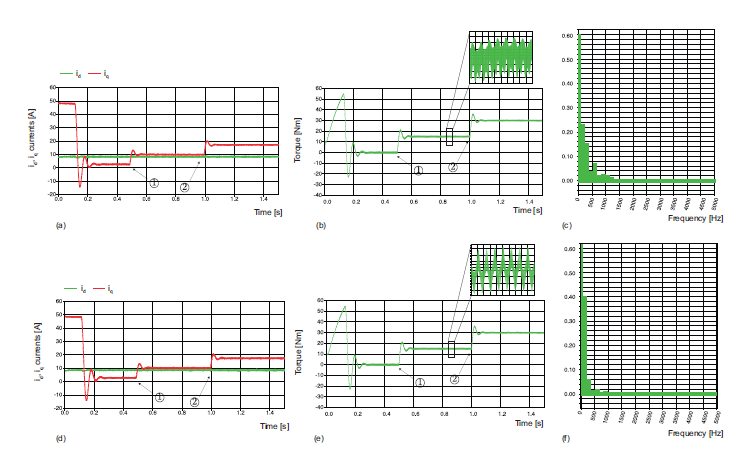 Figure 8: Simulation results under constant speed – variable load: (a) id iq currents using LS-PWM modulation (b) electric torque using LS-PWM modulation (c) torque harmonic profile using LS-PWM modulation (d) id iq currents using PS-PWM modulation (e) electric torque using PS-PWM modulation (f) torque harmonic profile using PS-PWM modulation
- I. Boldea and S. A. Nasar, “Electric drives,” CRC Press, vol. 24, June 30 2016.
- J. I. Leon, S. Vazquez, and L. G. Franquelo, “Multilevel converters: Control and modulation techniques for their operation and industrial applications,” Proceedings of the IEEE, vol. 105, no. 11, pp. 2066–2081, Nov 2017.
- S. Kouro, M. Malinowski, K. Gopakumar, J. Pou, L. G. Franquelo, B. Wu, J. Rodriguez, M. A. Perez, and J. I. Leon, “Recent advances and industrial applications of multilevel converters,” IEEE Transactions on Industrial Electronics, vol. 57, no. 8, pp. 2553–2580, Aug 2010.
- L. G. Franquelo, J. I. Leon, and E. Dominguez, “New trends and topologies for high power industrial applications: The multilevel converters solution,” in 2009 International Conference on Power Engineering, Energy and Electrical Drives, March 2009, pp. 1–6.
- X. Yuan, “Derivation of voltage source multilevel converter topologies,” IEEE Transactions on Industrial Electronics, vol. 64, no. 2, pp. 966–976, Feb 2017.
- J. Rodriguez, S. Bernet, B. Wu, J. O. Pontt, and S. Kouro, “Multilevel voltage-source-converter topologies for industrial medium-voltage drives,” IEEE Transactions on Industrial Electronics, vol. 54, no. 6, pp. 2930–2945, Dec 2007.
- D. G. Holmes and T. A. Lipo, “Pulse width modulation for power converters: Principles and practice,” Wiley-IEEE Press, vol. 24, October 3 2003.
- S. alberto Gonzalez, S. andres Verne, and M. I. Valla, “Multilevel converters for industrial applications,” CRC Press, vol. 8, July 22 2013.
- S. Kouro, M. Perez, J. Rodriguez, and B. Wu, “Four-level medium voltage multilevel converter for high power applications,” in ECCE Asia Downunder (ECCE Asia), 2013 IEEE, June 2013, pp. 1028–1033.
- L. M. Tolbert, F. Z. Peng, and T. G. Habetler, “Multilevel pwm methods at low modulation indices,” IEEE Transactions on Power Electronics, vol. 15, no. 4, pp. 719–725, Jul 2000.
- W. Bin, “High-power converters and ac drives,” Wiley-IEEE Press; 1 edition, pp. 1–468, 2006.
- C. A. Reusser, S. Kouro, A. Llor, R. Cardenas, and V. Yaramasu, “Permanent magnet synchronous generator wecs based on a four-level double star converter,” in 2017 IEEE 8th International Symposium on Power Electronics for Distributed Generation Systems (PEDG), April 2017, pp. 1–6.
- A. M. Llor, S. Kouro, C. Reusser, V. Yaramasu, and B. Wu, “Medium voltage 4-level double-starmultilevel converter using model predictive control,” in 2017 IEEE International Conference on Industrial Technology (ICIT), March 2017, pp. 136–140.
- J. Holtz, “The representation of ac machine dynamics by complex signal flow graphs,” IEEE Transactions on Industrial Electronics, vol. 42, no. 3, pp. 263–271, Jun 1995.
No related articles were found.