Direct Torque Control of Multiphase Doubly Converter-fed Asynchronous Machines Incorporating the Harmonic Torques
 , Luis Serrano-Iribarnegaray 1, Juan Carlos del Pino-López 2, Pedro Cruz-Romero 2
Adv. Sci. Technol. Eng. Syst. J. 3(4), 33–44 (2018);
 DOI: 10.25046/aj030405
Doubly fed asynchronous machines have an outstanding property: they can be operated up to twice rated speed delivering full rated torque. This paper presents, for the first time in the literature, a control system for multiphase asynchronous machines fed by Voltage Source Inverters (VSIs) both in stator and rotor that incorporates the harmonic torques. The system has three main and distinctive features: the independent control of the fundamental and harmonic torques, a very fast dynamic response for each one of these torques and a powerful method for selecting the best suited inverter state to achieve the evolution of the fundamental and harmonics flux linkage space phasors prescribed by the external control loops. The first feature is achieved through the decoupling of the multiphase machine provided by the Space Phasor Theory (SPhTh). The second one comes from the application of the General Approach for a very Fast TOrque Control (GAFTOC) principle. The third feature relies on using for multi-phase VSIs a simple but powerful switching-table based mode of operation that overcomes the limitations of the switching-table based modes of operation developed up to now, that only enable for the inverter to feed machines with no harmonic torques contribution.
1. Introduction
Multiphase machines are receiving increasing attention in the last two decades. This is due to several important advantages over their three-phase counterparts [1] like greater fault tolerance, reduced ratings of the electronic converters components, and the ability to make use of certain field harmonics (the greater the phase number, the higher the number of harmonics) in order to increase the total machine torque. This last possibility is only feasible for machines with relatively large winding factors for the low order harmonics (concentrated or nearly concentrated windings). The multiphase machines control development has been mainly directed so far to Induction Machines (IM) and to Permanent Magnet Synchronous Machines (PMSM). Multiphase Doubly Converter-Fed Asynchronous Machines (DCFAM) have not been dealt with in the technical literature so far. Yet, these machines show the great advantage over IM and PMSM of having an extended operating range to twice the rated speed while keeping the ability to provide full rated torque, thus effectively doubling the machine rated power. This outstanding property has only been considered so far in the case of three-phase DCFAM [2-4].
To extend the already developed Direct Torque Control (DTC) solutions for three-phase DCFAM to multiphase DCFAM with harmonic torques, Fig. 1, one must solve first three main problems:
- a) decoupling the fundamental and harmonic torques for their independent control,
- b) achieving a very fast dynamic response for each one of these torques, and
- c) developing a switching table based operation strategy for multiphase VSIs feeding machines with harmonic torques contribution.
The first problem is easily addressed though the multiphase machine decomposition and decoupling carried out in the SPTh, as presented in [5].
Once the muti-phase machine decoupling has been achieved, solving the second problem boils down to simply apply to each one of the independent machines the GAFTOC principle [6], in which the stator and rotor flux linkages space phasors, Ψ, play the fundamental role. In this regard, it should be underlined that, from a conceptual viewpoint, Field Oriented Control (FOC) and DTC, the two well-stablished high performance electric drives control methods, are two equivalent variants of the same and general GAFTOC principle, as explained in detail in section 7 of [6].
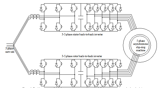 Figure 1. Doubly-converter-fed 5 phase asynchronous machine with 3-5 phase stator and rotor back-to-back inverters
In this regard, for multiphase IM control, both FOC and DTC methods have been used. In the first case control schemes that allowed torque increases by incorporating harmonic torques were early developed [7]. Regarding the DTC method (which is the field of main interest of this paper) it has been also applied to multiphase IM, especially in the last years [8–10]. Yet in all of these cases, in clear contrast to some FOC implementations, there has never been torque improvement by space harmonics. As to muti-phase PMSM, they are, from the mathematical viewpoint and the control complexity, much simpler (no rotor windings) than IM. However, even in these cases, the DTC of the machine, to the best of the authors’ knowledge, has also always been developed (with the exception of the results claimed in [11]), making use only of the fundamental torque [12-16]. As to the DTC of multiphase DCFAM, it has not been dealt with yet in the technical literature, not even in the simpler case of only fundamental wave operation.
With regard to the third problem, that is, with regard to the multiphase VSI operation, the first attempts at using a Space Vector Pulse Width Modulator (SVPWM) [17], were only able to control the fundamental voltage space phasor. Later on, [18] introduced a solution for the multiphase SVPWM with separated d-q spaces that allows the independent control of the d1q1-d3q3 voltage space phasors, but only with several constraints between their arguments and frequencies. These drawbacks were over-come in [19]. Still different improvements to the SVPWM operation of multiphase VSIs have been developed [20, 21]. In the case of multilevel converters, the choice of available inverter switching states increases considerably. In this respect [22] introduced a new multilevel multiphase SVPWM algorithm and [23] a generic digital Very High speed integrated circuit hardware Description Language (VHDL) module to implement it. All these strategies for selecting the inverter switching state require complex and time-consuming calculations, imply the use of Pulse Width Modulator (PWM) signal generators and assume, explicitly or implicitly, that the inverter can be modelled as an ideal controllable voltage source (which is not, since it has only a restricted a discrete number of switching states). Moreover, making use of an inverter operated this way for the machine control (usually in the FOC version) requires coordinate transformations (and thus a previous accurate determination of the angle between the involved reference frames). A switching-table based inverter operation strategy, initially introduced for three phase inverters [24], overcomes these drawbacks. In the case of multi-phase VSIs, this strategy has been first developed for inverters feeding 5-phase machines [8, 12, 13, 25]) and dual-three-phase machines [14, 16]. In a later and valuable paper [26], the switching-table based inverter operation strategy was extended to multiphase VSIs with an arbitrary odd number of phases, resorting to the so called virtual vectors definition methodology. In all of these cases, an ideal sinusoidal winding distribution has been assumed. Obviously, under this ideal assumption, only the fundamental space waves produce torque. Therefore, all of the methods developed until now are oriented to generate only fundamental voltage phasor precluding at the same time the presence of harmonic voltage phasors at the inverter output (suppression harmonics schemes). Indeed, these low order harmonic voltage phasors would drive large stator harmonic currents since the impedance (stator resistance plus leakage reactance) associated to these currents, which do not produce torque, is very small.
However, it seems neither logical nor the best option to disregard in all cases the possibility and advantages of torque enhancement through harmonics contribution in the case of the DTC of multiphase machines. In fact, these advantages have often been exploited in the case of FOC.
In view of the three aforementioned problems, this paper presents a switching-table based inverter operation strategy capable of simultaneously adjusting the fundamental and harmonics voltage space phasors, thus overcoming the limitations of the switching-table based modes of operation developed up to now (that only enable for the inverter to feed machines with no harmonic torques contribution). Then, once this tool is available, the paper develops a DTC of a multiphase DCFAM, with voltage source inverters both in stator and rotor, Fig.1, with fundamental and also harmonic torques that, moreover, are controlled in an independent and very fast manner. This system keeps the main ad-vantages of both three phase DCFAM (feasible operation up to twice the machine rated power and a balanced power share between the stator and rotor inverters) and multiphase configuration (greater fault tolerance, reduced ratings of the electronic converters components and torque enhancement through harmonics contribution).
The structure of this paper is as follows: first, section 2 describes by means of space phasors the fundamentals to split the actual multiphase machine into a set of much simpler machines, with only one effective flux linkage space phasor in stator, Ψstr , and another one in the rotor, Ψrot These fictitious machines are mechanically coupled, but electrically independent. Then, section 3 presents the new switching-table based operation strategy for multiphase VSIs feeding machines with useful harmonic torques. For the sake of simplicity, the strategy is explained on a five-phase machine. This strategy is computationally very light and can be easily extended to inverters with more than five phases and/or to multilevel inverters. Afterwards, section 4 develops in detail the scheme for the very fast and decoupled harmonic torques control which relies on the simultaneous and independent stator and rotor flux linkage space phasors control in each fictitious machine. The whole system has been checked in a five phase machine through an extensive set of simulations under different operating conditions, including step response to torque and speed references as well as speed reversals. Several of these simulations are displayed and commented in section 5. Finally, the main conclusions are summarized in section 6.
2. Multiphase Machines Decoupling Through the SPhTh
The approach overwhelmingly used for machines transient analysis is the so called magnetic coupling circuit approach (MCCA). Put it simply: the MCCA regards the machine as a network made up of resistances and inductances, many of which vary with the rotor position. This network is dealt with by means of complex matrix transformations.
The SPhTh for cylindrical or salient pole symmetrical machines with arbitrary number of phases and space harmonics has been presented in [5]. By contrast to the MCCA (machine as a network with rotor position dependent parameters), the SPhTh states that a machine can also be regarded as an electromechanical device that produces electromagnetic (field) waves with a restricted propagation capacity, namely they are forced to turn inside its air gap. These space waves, especially the scalar electric potential difference, the vector magnetic potential difference and the linear current sheet waves:
- can easily be characterized by dynamic space phasors: the voltage, flux linkage and current sheet space phasors, respectively
- can easily be correlated with the time phase quantities.
Notice that the SPhTh fully rejects space phasors to be mere mathematical entities without any physical meaning. In fact quite the opposite is true.
Another fundamental concept in the SPhTh is the dynamic m–phase system (DmPhS) of sequence g. By definition, the m quantities (m currents, m voltages, etc.) of an m-phase symmetrical winding are said to constitute a DmPhS of sequence “g”, if they meet the following equations: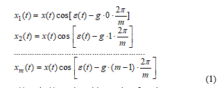
where x(t) and e(t) can be arbitrary time functions.
A DmPhS of sequence g only has two independent variables, x(t) and e(t). Thus, it can be fully characterized by a mathematical tool called the dynamic time phasor of the DmPhS of sequence g:![]()
Variables x(t) and ε(t) correspond with the instantaneous amplitude and position of the dynamic time phasor in its complex plane. Dynamic time phasors of the same sequence can be added up graphically and vectorially in an analogous manner as the classical Kapp’s phasors do. If the m phases of the winding are numbered 1,2 ,….,y, ….. (m-1), m, the quantity of the general phase y of system is obtained by simply projecting the phasor onto the phase axis in the complex plane of sequence g. That is (‑ stands for “real part of”):![]()
Obviously, if amplitude and speed of the dynamic time phasor are constant, the DmPhS in becomes a sinusoidal polyphase system of sequence g.
Sequences g and (m – g) are called complementary sequences. Any DmPhS of sequence g can always be converted into a DmPhS of sequence (m – g) in accordance with the equation (symbol * stands for conjugate complex):![]() By definition, the complementary DmPhS of the one in is:
By definition, the complementary DmPhS of the one in is: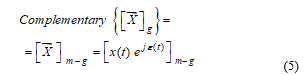 Comparing and it follows that the dynamic time phasors of two complementary DmPhSs are exactly equal except that their instantaneous arguments are opposite.
Let it be a seven-phase (m=7) stator symmetrical winding of a salient pole machine and consider the numerous stator electric potential difference space waves which appear at the stator surface with arbitrary changes in their amplitudes and speeds. It has been proven [5] that each of these waves with p, 8p, 15p, etc. pole pairs (that is, each of the harmonic waves of relative order h = 7q + 1 with q = 0, 1, 2, 3, etc.) produces in the winding a voltage DmPhS of sequence 1. Likewise, each of the waves of order h = 7q + 2; h‑ = 7q +3, etc. produces a voltage DmPhS of sequence 2, 3, etc, respectively. Therefore, for a 7-phase stator winding all of the electric potential difference waves in axial direction at the stator surface can be classified into seven families. The instantaneous amplitudes and positions of the different waves belonging to the same family are, in the general case, quite different from one another. However, all of them originate DmPhSs of the same sequence which can be added up to give a resultant DmPhS of this same sequence. Thus, the combined action of all of the waves of one family on the phase voltages can be characterized by just one equivalent or effective voltage space phasor. Or alternatively: the resultant voltage DmPhS produced by a whole family of waves can be imagined to be produced by one only effective or equivalent space wave, the phasor of which is just the effective space phasor of the waves family.
Moreover, the two effective voltage DmPhSs produced by the families with h = 7q +1 and h = 7q +6 are DmPhSs of complementary sequence. Therefore, they can be added up so that just one space phasor suffices to characterize the combined action of both families (which form a group of space waves with h = 7q 1). The same statement applies to the families with h = 7q 2 as well as to the families with h = 7q 3. Thus, the combined effect of all of the electric potential difference waves on the voltages of the seven phases in any dynamic state is fully characterized by just four effective voltage space phasors (one of which being the homopolar phasor). These conclusions apply too to the magnetic vector potential difference space waves (space phasors Y), and can be extended to a symmetrical winding with an arbitrary number of phases, m.
Similarly, a current DmPhS of sequence g flowing through the stator symmetrical m-phase winding of a salient pole machine produces only current sheet space waves of relative order h = mq ± g. Its complementary current DmPhS produces exactly the same space waves group, except that the instantaneous speed of any wave in this second case is opposite to that of the first case.
In summary, each one of the different u, Y and i effective dynamic space phasors existing in the multiphase machine is related to one specific and independent group of space harmonics. This physical reality has been analyzed in detail in [5] and constitutes the true base that enables to “untangle” rather easily the structure of a constant air gap multiphase machine (either PMSM, IM or DCFAM) and to split it into an equivalent set of much simpler machines, mechanically coupled but electrically independent. Each one of these machines is associated to each one of the independent group of space harmonics mentioned above. As already pointed out in [5], it should be indicated here too that the authors in [27] had already dealt with the particular case of PMSM (no rotor winding and constant rotor magnetic field influence into the stator windings) following an approach completely different from the SPhTh. Resorting to different analysis tools (endomorphism, orthonormal base of eigenvectors, etc) they arrived at decoupling laws for PMSM mathematically fully equivalent to the general results presented in [5].
On the other hand, it is well known that only the interaction of stator and rotor space waves with the same pole number can produce torque. Assume again a symmetrical asynchronous machine with seven phases in stator and rotor. If one applies, exclusively, e.g., a current DmPhS of sequence g = 5 (or g=2) to the stator and another one to the rotor, the space waves (and their associated torques) of the two complementary families h = 7q±2 can be controlled in any dynamic state without modifying the space waves of the remaining families. This is just the physical base underlying the decoupled control of the multiphase machine.
Moreover, by contrast to mains-connected machines, in multiphase converter-fed machines it is not necessary to take into account all the members of each wave family for determining the torque because in this case only the head members of their groups (that is, the harmonics with the lowest pole number) are able to provide a non-negligible instantaneous torque contribution. Notice, e.g. that in all control schemes of converter-fed three phase induction machines presented in the technical literature only the fundamental waves (that is, the head members of the stator and rotor waves families) are considered as to the torque production. The impact on the machine torque of the harmonic waves is considered negligible [30]. Therefore, in what follows, only the head members of each group of two complementary waves families will be considered (e.g., for a seven phase winding without homopolar components these head members are the fundamental, the third and the fifth harmonic space waves).
A three phase doubly converter-fed asynchronous machine without homopolar components only has one voltage and one flux linkage effective space phasor in the stator, and the same applies to the rotor. Its phasorial stator electric equation reads: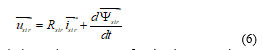 In the DTC technique, since stator emf and voltage are almost equal quantities (if the resistive voltage drop is neglected), stator voltage space phasor guides the stator flux linkage phasor forcing it to approach a circular trajectory, so that this way only rotational emfs are induced, Figure 2.
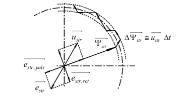 Figure 2. Stator flux linkage phasor changes in a modulation step and stator pulsational and rotational EMFs space phasors
Indeed, if , then according to :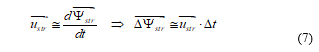
that is, during any converter control cycle the variation of the Ystr phasor takes place very closely in the direction of the voltage space phasor selected during the interval, Figure 2. In other words, the amplitude of Ystr is controlled by using radial voltage phasor components (that is, pulsational emf, which only affects the flux linkage module), whereas the torque is adjusted by applying tangential voltage components, that is, rotational emf, directly related to the torque generation, as explained in detail in [6], and which only affects the flux linkage phasor speed, producing a “tangential pull” on it.
Just as in three phase machines without homopolar components, the decoupled machines obtained from the actual multiphase machine also have only one effective voltage and one effective flux linkage space phasor in stator and rotor. Thus, as explained in [5], the electric polyphase winding (stator or rotor) equation of any of these independent machines reads:
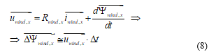 where x stands for stator or rotor. For more details on this subject, refer to [5].
3. Switching-Table Based Operation Strategy for Multiphase VSIs Feeding Machines with Useful Harmonic Torques
Single phase PWM presents a single degree of freedom: the ratio of ton to toff. Three phase PWM present three degrees of freedom, although only two of them are effective in terms of the load voltage space phasor due to the usual three wire connection. In DTC these two degrees of freedom result in the ability to obtain the most suitable load voltage space phasor out of the only 23=8 possible switching state combinations to modify the magnitude and angle of the stator flux linkage phasor prescribed by the external control loop. It is apparent that for every additional converter phase a new degree of freedom is available. Then the problem arises of finding a suitable connection between the control variables in a multiphase load and the corresponding VSI switching state selection.
In a 5-phase two level converter there are 25=32 switching states available (two of them resulting in the same null voltage space phasor). Therefore, they produce 31 different voltage space phasors of the first and of the third harmonic space waves. Let us consider a 5-phase machine, whose phase 1 is set at the real axis, fed by a converter with Vbus dc bus voltage. The status of each of the 5 inverter legs is defined by a set of five Boolean variables, [sw]x , for which 1 means that phase x is connected to the dc bus positive terminal in Figure 1, and 0 that it is connected to the negative terminal. Each one of the 32 inverter switching states is then defined by the 5 bits of the following switching state index, 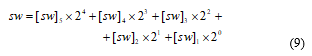
Likewise, the voltage of any x-phase measured to the dc bus mid-point is given by![]()
The fundamental and 3rd harmonic voltage space phasors are calculated from the phase terminal voltage according to: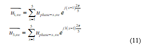
The 31 circles in Figure 3 mark the affixes of the 31 different voltage space phasors of the fundamental wave in its phasorial domain. Analogous information provide the 31 circles in Figure 4 with regard to the third harmonic. These voltage space phasors for the 32 switching states are then organized as column vectors: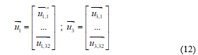
Notice that the index or number of each row in (12) expressed in binary system coincides with the switching state index, sw, that originates the voltage space phasor corresponding to the mentioned row.
The first step into the selection of the adequate switching state is to evaluate every state in terms of its ability to change magnitude and angle of the two flux linkage space phasors, Y1 and Y3. To do so the complex phasorial plane of each space harmonic is divided into 20 equal sectors (The reason to divide each one of the two phasorial domains into 20 sectors is to assure that while each flux linkage space phasor remains within a given sector, the real and imaginary parts of all 30 non null voltage space phasors, calculated in a reference frame aligned with the flux linkage space phasor, do not change their signs). Then the real and imaginary parts of the voltage space phasors of the first and third harmonics corresponding to each switching state combination are calculated in a reference frame in which the real axis is directed along the middle of the sector, Figure 3 and Figure 4.
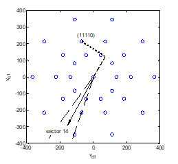 Figure 3. Real (thick dashed) and imaginary (thick dotted) parts of the fundamental voltage space phasor when the fundamental flux linkage space phasor lies in sector 14. The inverter switching state considered is 11110.
According to the winding equation and section 2, Figure 2, it is just these real and imaginary parts that quantify how well suited each switching combination is to quickly modify the corresponding flux linkage space phasor magnitude and angle respectively. For example, the higher and positive the real part of the voltage phasor the better suited to increase flux linkage phasor magnitude, while the higher and negative the imaginary part the better suited to rotate the flux linkage space phasor backwards.
Let us consider the inverter switching state (11110) during a time interval at which the first harmonic flux linkage space phasor lies, e.g., within sector 14 while, at this same time, the third harmonic flux linkage space phasor lies in sector 11. Figure 3 shows for the mentioned switching state index, sw = (11110), the corresponding real and imaginary parts of the fundamental voltage space phasor (calculated in a reference frame aligned with the fundamental flux linkage space phasor). Analogous information provides Figure 4 related to the third harmonic voltage space phasor.
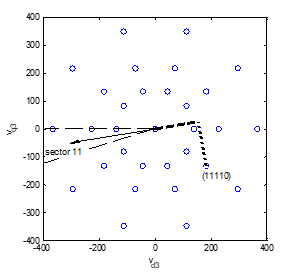 Figure 4. Similar to Fig. 3, but for the third harmonic space wave and when Ψ3 lies in sector 11
The result of these operations performed for all sectors and all switching states are four 32×20 matrices (matrices MT1 MT3 MΨ1 and MΨ3 in Figure 6). These matrices, , are the imaginary or real parts of the matrices obtained as the complex product of the voltage space phasors column vectors times (uγ/2)* :
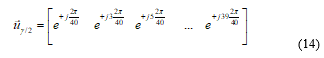
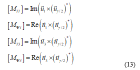 where (uγ/2)* is the row vector formed by the complex conjugates of the 20 sector central unitary vectors, according to the following equation:
 In these matrices, each row is associated with one of the 32 available switching states in the 5-phase converter, while each one of the 20 columns is associated with one of the 20 sectors in which the phasorial domain for the fundamental and 3rd harmonic has been split into.
Notice that, once selected, e.g., sector 11, Figure 4 shows how the imaginary and real parts of the third harmonic voltage space phasor for one specific switching state can be obtained. Yet, this operation has to be performed, in this sector, for the 32 possible inverter switching states. The 32 x 2 values obtained this way are just the 32 values in column 11 of matrices MT3 and MΨ3. Thus, matrices MT1 MT3 MΨ1 and MΨ3 express the ability of the 32 inverter switching state combinations to modify angle (torque) or magnitude (flux) of the fundamental or of the third harmonic flux linkage space phasors when these phasors lie in each one of the 20 sectors. From each one of these four matrices, and by means of the actual Ψ sector calculators, the system extracts the appropriate column, Figure 6, that is, the column corresponding to the sector in which the actual fundamental (or third harmonic) flux linkage space phasor lies (the actual sector is simply and directly determined from the Ψ phasor angle). Each one of these four columns is then weighted; or, more precisely, it is multiplied by the normalized desired trend (obtained from the torque and flux linkage comparators) in magnitude and angle of both flux linkage space phasors.
These weights for the stator and rotor fundamental and third harmonic torque and flux control are those shown in Figure 6 as dt1, dp1, dt3, dp3. They are equal to the actual torque or flux error (ΔT, ΔΨ) in per unit of the corresponding rated value multiplied by a suitable weighing factor, k, that is:
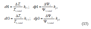 where the k-values in have been chosen in this paper equal to:
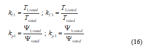
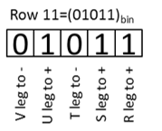 Figure 5. Five-phase Inverter switching legs status as determined by individual bits of row number conversion to binary: example for row number = 11. Inverter output phases are designed in this figure as V, U, T, S and R
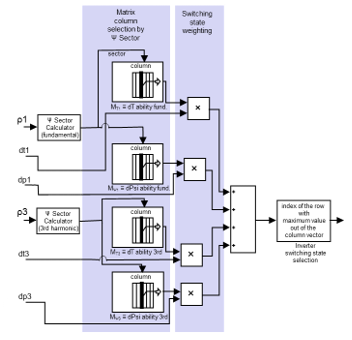 Figure 6. Operations flow for the 5-phase DTC: sector calculators, columns selection, weighing (products), combined switching state ability to modify magnitude/angle of the flux linkage space phasors (addition), best inverter switching state selection and, finally, binary conversion to get the inverter legs switching states. ρx: flux linkage space phasor angle (1: fundamental; 3: 3rd harmonic); dtx and dpx: normalized desired trend in magnitude and angle of the flux linkage space phasors.
The four column vectors mentioned above are added up to form a single column vector, and then its row with the highest value is selected. From this selected row the inverter switching state is obtained immediately: indeed, in accordance with the comments just after eq. (12), the row number conversion to binary directly yields the required switching state for all five inverter legs, Figure 5. This procedure overcomes the unsolved problem found in switching-table based operation strategy of multiphase VSIs in order to select the inverter switching state which is best suited to simultaneously modify magnitude and angle of the fundamental and also of the higher harmonic flux linkages space phasors in the way prescribed by the external control loops. (Remember that the space phasors Ψ play the central role in the GAFTOC strategy).
In summary, the switching state selection process is divided into two main steps. First, each switching state ability to force changes in the magnitude and angle of the flux linkages space phasors of fundamental and third harmonic is calculated (this step is carried out off-line and stored as an array in the controller memory). Second, depending on the magnitude and torque/angle errors for the flux linkage space phasors, the best suited out of the 32 available switching states is selected (this step needs only real products to be performed and is carried out on-line).
The whole process is then very light in terms of computational requirements as only basic operations and in small number are required. It needs to be carried out just once in every modulation period. The most computationally heavy operations for the matrices calculation are carried out off-line and only the resulting arrays are stored in the control system memory. It is important to notice too that this strategy can directly be extended to inverters with more than 5 phases and/or to multilevel inverters.
4. Independent and Very Fast Control of the Fundamental and Harmonics Torques of Multiphase Doubly Converter-Fed Asynchronous Machines
The Direct Torque and Stator and Rotor Flux Control (DTSRFC) of the three phase DCFAM in [4] actually set the basis for the very fast control of the fundamental and harmonics torques of the multiphase DCFAM.
The fundamental idea behind a very fast torque control strategy was already applied to develop the DTSRFC: In steady state of polyphase machines only rotational emfs appear in all of their windings and, therefore, these are just the emfs (that is, the ones related to the electromechanical energy conversion process) that have to be enhanced. The pulsational emfs (that is, the ones associated to amplitude variations of the flux linkage space phasors) should be kept null. This essential idea (pulsational emfs are a waste of resources and time as to the torque production) should be extended to transient states too if a torque control with very fast dynamic response and an efficient utilization of the machine (and of the power conditioning unit) is desired. This is the GAFTOC principle [6].
The three phase doubly converter-fed asynchronous machine is especially well suited to put into practice such control strategy. Indeed, to keep the pulsational emfs null in all of its windings, it suffices to operate the stator and rotor converters so as to maintain Ystr and Yrot magnitudes constant. Should there still be any degree of freedom in the operation of the converters, it must be used so as to force the biggest possible rotational emfs (speed of the flux linkages space phasors).
In a three phase machine, the following equations hold [3,4]: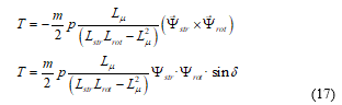
It should be noticed [5] that space phasors are not physical vectors but (mathematically seen) complex time-varying quantities. Thus, the vectorial product in (17) should be interpreted as a formal operation.
Therefore, in the three phase machine the control is performed, [4], by keeping the Ystr and Yrot modules constant and adjusting the torque through the angle, δ, between both phasors, Figure 7, according to (17). This same procedure must simply be extended to all of the fictitious independent machines of the multiphase machine.
A multiphase inverter enables, for each one of these fictitious machines, two degrees of freedom, that is, to freely adjust magnitude and angle of the corresponding flux linkage space phasors, Ψ [5]. Therefore, in a multiphase DCFAM (two inverters) this control strategy still leaves one degree of freedom to completely define the Ψstr and Ψrot references in each fictitious machine. In the particular case of three phase machine this remaining degree of freedom is used to force a balanced share of electric power between both inverters. For more details, see [4].
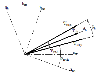 Figure 7. Stator, rotor and magnetizing flux linkage space phasors and flux load angle d for the space harmonic of relative order h. Systems (arot,brot), (astr, bstr), (dh, qh): rotor, stator and magnetizing phasorial reference frames for the harmonic h.
In multiphase machines a new additional and important control task arises, namely how to adjust the suitable value and orientation of the harmonic magnetizing flux linkage space waves with regard to the fundamental one. In this sense, in a machine with the classical sinusoidal air-gap induction distribution only in the narrow region where the induction is maximum becomes the iron saturated to the desired value at any one instant. Yet, it seems clear that the magnetic circuit would be better utilized if the air-gap induction wave approximates a nearly rectangular one. Notice, nevertheless, that the control scheme in Figure 8 below enables to easily obtain any desired induction waveform. To this end, it suffices to choose the suitable amplitudes of the different harmonic flux linkage space waves (block flux linkage reference distribution in Figure 8) and their orientations with respect to the fundamental magnetizing flux linkage wave . These values are chosen to obtain (in machines with a high number of phases) an air gap induction wave of quasi-rectangular shape.
Notice too, from another perspective, that the possibility of obtaining almost any desirable air gap induction waveform in machines with a high number of phases relies on the fact that, with increasing phase number, the converters can inject additional current DmPhSs of different sequences, g, with the appropriate ε(t) values in (1), which is valid for steady and transient states.
In this regard, it should be remembered from section 2 that the only condition to have different waves groups is to inject (through the suitable currents) dynamic time current phasors of different (and not complementary) sequences. For instance, in the particular case of steady state of a five phase machine, in order to get the two wave groups of h = 5q ± 1 and h = 5q ±2, it is only required to feed the winding, simultaneously, with two suitable sinusoidal polyphase current systems, A and B. In system A the phase angle between the currents of two consecutive winding phases should be γ or 4γ (that is, gA = 1 or 4), with γ=2π/5. In system B it should be 2γ or 3γ (gB = 2 or 3). Obviously, the functions ε(t) are in this case of sinusoidal currents: εA(t) = ωA·t and εB(t) = ωB·t, where ωA and ωB are two arbitrary constant values. If in addition it is desired that the head members of both wave groups turn in the same direction and at the same speed, then one must choose gA =1, gB =3 (or gA‑ =4, gB =2) and ωB=3ωA. In other words, and contrary to some statements in the literature, the frequency ωB = 3ωA does not imply the existence of a third harmonic wave (which is tied to the sequence g of the current DmPhS) but only determines its speed [5].
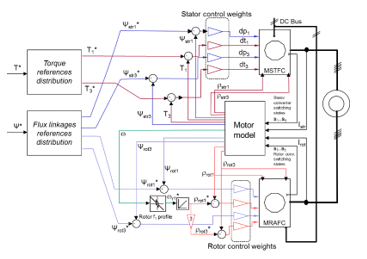 Figure 8. DTC diagram of a five phase doubly converter-fed asynchronous machine incorporating the harmonic torques. Symbol * stands for reference values. For a detailed explanation, see text.
The fact that, as above indicated, the air gap induction wave approximates a quasi-rectangular shape leads to a resultant magnetizing flux linkage wave that approximates a symmetrical triangular distribution so that one peak of all the magnetizing flux linkage space waves for the space harmonics of relative order 1, 3, … must occur at the same air gap angular position. In other words, the magnetizing flux linkage space phasors must be oriented in such a way that their angles (measured in their respective phasorial domains) meet the following equation:![]()
The diagram in Figure 8 shows the global control structure. It starts with the machine total torque and flux linkages references: the machine torque reference is the output of the speed controller (not shown in the figure) while the flux linkages reference can be either kept constant or suitably adjusted in the case of field weakening operation. The torque references distribution block provides the torque share for the fundamental and the third harmonic. An analogous statement hold for the flux linkages references distribution block. Then, the stator flux linkage and torques references are compared with the actual machine values and the errors are divided by the corresponding rated values and multiplied by the suitable weighing factors. The results of these operations, (15), are the inputs dt1, dp1, dt3, dp3 to the stator Multiphase Stator Torque and Flux Controller (MSTFC) block, which has the structure of Figure 6. As for the rotor, the flux linkages comparators are similar to those of the stator. However, the role of the stator torque comparators is played here by the flux linkage space phasor angle comparators: the machine speed sets (by means of the rotor frequency profile, Figure 9) the rotor fundamental frequency. This rotor frequency is integrated to provide, first, the rotor fundamental flux linkage space phasor angle and thereafter, making use of (19), Figure 8 bottom, the angle of the rotor third harmonic space phasor. Then, the references for amplitude and angle of the first and third harmonic rotor flux linkage phasors are compared with the actual values in the machine, and the errors are multiplied by the corresponding rotor control weights. Finally, the results of these operations are the inputs dt1, dp1, dt3, dp3 to the rotor Multiphase Rotor Angle and Flux Controller (MRAFC) block, which also has the structure of Figure 6.
To synthetize and highlight the hard core of the diagram in Figure 8 let us consider as a first step only the fundamental waves. The input data required to operate the rotor converter are, in summary, the magnitude and angle errors of the rotor flux linkage space phasor. In turn, the input data required to operate the stator converter are the magnitude and angle errors of the stator flux linkage space phasor (this last one, that is, the error of the stator flux linkage space phasor orientation with respect to the rotor flux linkage phasor is indirectly given by the required fundamental torque, according to ). This way, both fundamental flux linkage space phasors can be forced upon the stator and the rotor by the corresponding converter. This scheme is repeated for all of the harmonic waves in a decoupled way (for the harmonics, the rotor phasor angle is given by specifying the position of the harmonic magnetizing space wave with respect to the fundamental one). And since, moreover, the modules of all of the harmonic flux linkage phasors are always kept constant, there are no pulsational emfs induced in the machine (GAFTOC principle) and, therefore, the torque contribution of the fundamental and the harmonics can be adjusted independently and very quickly.
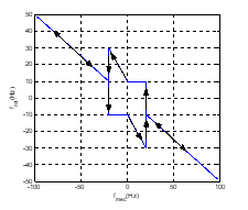 Figure 9. Rotor frequency profile
Let us introduce a final and brief comment on the rotor frequency vs. speed profile chosen, Figure 8 and Figure 9. This profile, as explained in [4], assures a balanced power share between the stator and the rotor converters and, at the same time, avoids operation at voltages close to converter ceiling voltage (higher frequencies) but maintaining a similar minimum converter frequency both in stator and rotor all over the speed range. A minimum frequency is important to allow accurate estimation of stator and rotor total flux linkage space phasors with simplified machine models.
5. Simulation Results and Discussion
There are several proposals to distribute the torque and flux linkages between the fundamental and the higher harmonic waves in asynchronous multiphase machines [28,29]. All of them have in common that the increase in machine torque is achieved through an increase of the fundamental air gap induction, Figure 10. This way, the machine pole flux is increased too. However, as the maximum value of the air gap magnetic induction is kept equal to that of sinusoidal operation, iron losses are accepted in the mentioned proposals to be scarcely affected. In accordance with these ideas, in this paper the third harmonic induction amplitude has been set to 0.18 of the fundamental wave. This results in a third harmonic torque contribution equal to 3.6% that of the fundamental for a total rms current equal to the one for sinusoidal operation.
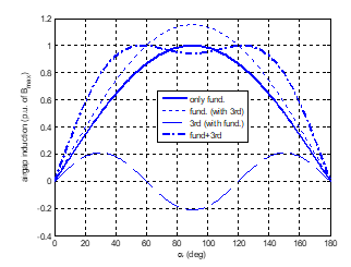 Figure 10. Air gap induction wave in a 5-phase machine for sinusoidal (solid line) and quasi-square wave operation (dash-dor line). The maximum value of the air gap induction is equal in both cases.
An extensive set of simulations, the results of some of which are displayed below, have been carried out on a five phase machine using Matlab-Simulink. The main machine parameters are listed in table 1.
Table 1 5.5 kW Drive Main Parameters
| General | P=5,5kW, n=1438 rpm, h=0.863, cos φ=0.83
J=0.05 kg·m2, stator and rotor phases: 5 Converter maximum frequency 8 kHz |
| Stator | U=138 V, I=10.9 A, f=50 Hz
R=0.75Ω, Lσ=4.3mH (leakage,), Lμ,1=80.4mH (main ind.) ; concentrated winding (one full pitch coil per pole pair). |
| Rotor | U=138 V, I=9.4 A, f=50 Hz
R=0.54Ω, Lσ=3.1mH (leakage) Lμ,1=80.4mH (main ind.); concentrated winding (one full pitch coil per pole pair). |
The first point to note, Figure 11, is the ability of the control system to comply with one of its main objectives: the fast and decoupled control of the torques produced by the harmonics 1 and 3, while keeping constant the stator and rotor flux linkages space phasors magnitudes of both fundamental and third harmonic, as required by the GAFTOC. In the first row of graphs the step torque changes attest the very high dynamic response to torque reference changes while in the second and third row the excellent decoupling between torque and flux linkage, both for stator and rotor and for the fundamental and third harmonic, is clearly apparent. The last row of graphs shows on the one hand (by comparison with the first row) the direct relationship between torque and q-axis current and, on the other hand, the approximate sharing of the magnetizing current between stator and rotor. (Although only the stator d-axis current is plotted, it can be seen how it is approximately kept to one half of the machine magnetizing current, meaning that the rotor provides the remaining half).
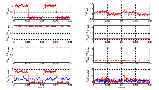 Figure 11. Rated torque step response at rated speed: left fundamental, right third harmonic. Up: Torque reference and actual value. Center: stator (above) and rotor (below) total flux linkage magnitude. Bottom: stator d, q currents and machine magnetizing current (dotted).
Figure 12 shows a double speed reversal with positive and negative acceleration where the role of the rotor frequency profile (as explained in Fig. 4) clearly appears: at low speed both stator and rotor frequencies are kept at least over a minimum value set at 10 Hz so as to prevent operation at low frequencies and this way improving the accuracy of the stator and rotor flux estimators.
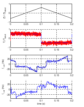 Figure12. Speed reversal (positive and negative acceleration). Above: speed. Middle-up: Fundamental torque. Below: rotor (up) and stator (down) fundamental frequencies.
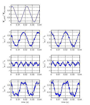 Figure 13. Machine operation at full load and twice rated speed. Left: Normalized magnetizing flux linkage of stator phase R (top), stator phase currents for sequence 1 (above) and 3 (center) and total phase current (below). Right: rotor phase currents for sequence 1 (above) and 3 (center) and total phase current (below).
Figure 13 shows the stator and rotor phase currents at full load (rated stator rms current) and twice rated speed operation and the quasi-triangular magnetizing flux linkage of phase R. This figure shows, for stator and rotor, the current share between the fundamental and the third harmonic to provide the total required machine torque. The quasi-square waveform of the total phase current (as opposed to the sinusoidal current waveforms only possible up to now with previous multiphase DTC) clearly shows the third harmonic contribution to the torque enhancement achieved not exceeding the rms current rated value. It is worth noticing how a total torque of 116% of rated torque requires a relatively modest third harmonic torque of about 4% of rated torque to be added to the 112% of rated torque provided by the fundamental space waves.
The torque increase because of the third harmonic contribution appears also clearly when the 5-phase drive is compared with an equivalent three-phase drive with the same rated power and phase current as in Fig. 14 and Fig. 15. The right side in both figures shows the performance of the conventional 3-phase DCFAM under DTSRFC (as introduced in [4] and also explained in [6]) with the expected sinusoidal phase flux linkage and phase currents both in stator and in rotor. On the contrary, the left side in Fig. 15 clearly shows the quasi-triangular phase flux linkage and the associated quasi square-wave stator and rotor phase currents as in Figure 13. The reduced maximum current for the 5-phase drive (due to the harmonic content with equal rated rms total current) can be clearly appreciated also in comparison with the sinusoidal phase current in the 3-phase drive.
One can easily check that the results on the right side of Fig. 14 and Fig. 15 are a particular case of the results on the left side. Mathematically: reducing the degrees of freedom in the DTC of the multiphase DCFAM while keeping the GAFTOC strategy results in the DTC scheme of the three-phase machine (no contribution of the harmonic torques, associated to the fictitious harmonic machines). Three-phase DCFAM have already been dealt with in the literature, since they show the great advantage over three-phase IM and PMSM of having an extended operating range of up to twice the rated speed while keeping the ability to provide full rated torque and a balanced power share between the stator and rotor inverters. Yet, multiphase DCFAM have not been dealt with so far, not even in the simpler case of only fundamental wave operation. This problem has been addressed in this paper in the general case (arbitrary odd number of phases and contribution of harmonic torques). And, as shown by the figures and discussion in this section, the system presented keeps the main advantages of both the three-phase DCFAM (doubling the power) and of the multiphase configuration (greater fault tolerance, reduced ratings of the electronic converters components and torque enhancement through harmonics contribution).
6. Conclusions
Constant air gap multiphase PMSM, IM and DCFAM can be decomposed into an equivalent set of three-phase machines mechanically coupled but electrically independent. Thus, their torques can be controlled independently. On the other hand, each multiphase inverter enables for each one of these fictitious machines two degrees of freedom, so that magnitude and angle of either Ψstr or Ψrot can be adjusted in each machine trough the inverter.
The very fast torque control general strategy GAFTOC has been applied, in its DTC version, to each one of the independent
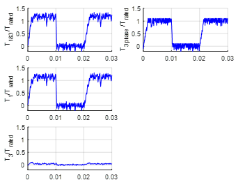 Figure 14. Direct torque and stator and rotor flux control of a DCFAM torque step response: comparison for 5-phase (left) and 3-phase (right) drives. Total torque (top) and torque produced by fundamental (middle) and 3rd (bottom) air gap harmonic (only for the 5-phase drive).
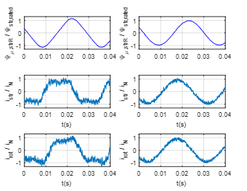 Figure 15. Direct torque and stator and rotor flux control of a DCFAM steady state operation at rated phase current: comparison for 5-phase (left) and 3-phase (right) drives. Top: stator phase flux linkage in p.u. of rated phase flux linkage. Middle and bottom: stator and rotor phase current, respectively, in p.u. of rated phase maximum current.
fictitious machines. GAFTOC states that the magnitudes of both Ψstr and Ψrot of each machine must remain constant and that its torque must be adjusted by means of the angle between Ψstr and Ψrot, This strategy, with two inverters available, still leaves one degree of freedom to completely define the Ψstr and Ψrot references. This degree of freedom has been used, in the main machine (which provides most of the power) to force a balanced power share between both inverters, and, in the remaining machines, to suitably align their magnetizing flux linkage space waves to the fundamental one.
In addition, in order to be able to apply the mentioned DTC to a DCFAM with an arbitrary odd number of phases, this paper also presents a new and very general switching-table based mode of operation for multiphase VSIs that, moreover, is computationally very light and can be easily extended to multilevel inverters. Previous switching-table based mode of operation for multiphase VSIs enabled to take profit only of the machine fundamental wave (harmonic suppression schemes).
The whole system has been tested through an extensive set of simulations in a five phase DCFAM. They show that, as predicted by the theory, a very fast torque control of the DCFAM is possible: a) throughout the whole operational speed range b) keeping an excellent decoupling between torque and flux linkage, and c) independently for the fundamental and the harmonic torques. As to this point it should be underlined that the control of multiphase DCFAM is far more complete and versatile than that of multiphase IM and PMSM, simply because the degrees of freedom to design the control system are now double than before (two inverters instead of one). Reducing in different ways the degrees of freedom in the DTC of the DCFAM while keeping the GAFTOC strategy leads to the different DTC structures presented in the literature for the classic three-phase machines.
The main disadvantage of the DCFAM versus the alternative with IM or PMSM is the need for a slip rings rotor. However, even if the drive design around an IM or a PMSM were always the best option (which is dubious for high power applications), the multiphase machine decoupling and the fast and independent harmonic torque control proposed in this paper can still be applied to the DTC of multiphase IM and PMSM to great advantage.
This research did not receive any specific grant from funding agencies in the public, commercial, or not-for-profit sectors.
Conflict of Interest
The authors declare no conflict of interest.
- E. Levi, R. Bojoi, F. Profumo, H. Toliyat, S. Williamson, “Multiphase induction motor drives – a technology status review,” Electric Power Applications, IET, vol. 1, no. 4, pp. 489–516, July 2007.
- Y. Kawabata, E. Ejiogu, T. Kawabata, “Vector-controlled double-inverter-fed wound-rotor induction motor suitable for high-power drives,” Industry Applications, IEEE Transactions on, vol. 35, no. 5, pp. 1058–1066, 1999.
- G. Poddar V. T. Ranganathan, “Direct torque and frequency control of double-inverter-fed slip-ring induction motor drive,” Industrial Electronics, IEEE Transactions on, vol. 51, no. 6, pp. 1329–1337, Dec 2004.
- J. Martinez-Roman L. Serrano-Iribarnegaray, “Direct torque and stator and rotor flux control doubly converter fed induction machines,” in IEEE Mediterranean Electrotechnical Conference, 2006. MELECON 2006. IEEE, 2006, pp. 1158–1161.
- L. Serrano-Iribarnegaray, “Space phasor theory and control of multiphase machines through their decoupling into equivalent three-phase machines,” Electrical Engineering, vol. 96, no. 1, pp. 79–94, 2014.
- L. Serrano-Iribarnegaray J. Martinez-Roman, “A unified approach to the very fast torque control methods for dc and ac machines,” Industrial Electronics, IEEE Transactions on, vol. 54, no. 4, pp. 2047–2056, Aug 2007.
- H. Xu, H. Toliyat, L. Petersen, “Five-phase induction motor drives with dsp-based control system,” Power Electronics, IEEE Transactions on, vol. 17, no. 4, pp. 524–533, Jul 2002.
- L. Zheng, J. E. Fletcher, B. W. Williams, X. He, “A novel direct torque control scheme for a sensorless five-phase induction motor drive,” IEEE Transactions on Industrial Electronics, vol. 58, no. 2, pp. 503–513, Feb 2011.
- D. Casadei, G. Serra, A. Tani, L. Zarri, “Direct torque control for induction machines: A technology status review,” in Electrical Machines Design Control and Diagnosis (WEMDCD), 2013 IEEE Workshop on, March 2013, pp. 117–129.
- M. Bermúdez, H. Guzmán, I. González-Prieto, F. Barrero, M. J. Durán, X. Kestelyn, “Comparative study of dtc and rfoc methods for the open-phase fault operation of a 5-phase induction motor drive,” in IECON 2015 – 41st Annual Conference of the IEEE Industrial Electronics Society, Nov 2015, pp. 002702–002707.
- X. Kestelyn, E. Semail, D. Loroil, “Direct torque control of multi-phase permanent magnet synchronous motor drive: application to a five-phase,” in IEEE International Conference on Electric Machines and Drives, 2005., May 2005, pp. 137–143.
- Y. Gao L. Parsa, “Modified direct torque control of five-phase permanent magnet synchronous motor drives,” in APEC 07 – Twenty-Second Annual IEEE Applied Power Electronics Conference and Exposition, Feb 2007, pp. 1428–1433.
- A. Yousefi-Talouki, S. A. Gholamian, M. Yousefi-Talouki, R. Ilka, A. Radan, “Harmonic elimination in switching table-based direct torque control of five-phase pmsm using matrix converter,” in 2012 IEEE Symposium on Humanities, Science and Engineering Research, June 2012, pp. 777–782.
- K. D. Hoang, Z. Q. Zhu, M. Foster, “Optimum look-up table for reduction of current harmonics in direct torque controlled dual three-phase permanent magnet brushless ac machine drives,” in 6th IET International Conference on Power Electronics, Machines and Drives (PEMD 2012), March 2012, pp. 1–6.
- X. Ma, Y. Yu, H. Zhang, W. Wang, L. Liu, “Study on direct torque control of dual y shift 30 degree six-phase pmsm,” in 2015 IEEE 10th Conference on Industrial Electronics and Applications (ICIEA), June 2015, pp. 1964–1968.
- K. D. Hoang, Y. Ren, Z. Q. Zhu, M. Foster, “Modified switching-table strategy for reduction of current harmonics in direct torque controlled dual-three-phase permanent magnet synchronous machine drives,” IET Electric Power Applications, vol. 9, no. 1, pp. 10–19, 2015.
- Y. Zhao T. Lipo, “Space vector pwm control of dual three-phase induction machine using vector space decomposition,” Industry Applications, IEEE Transactions on, vol. 31, no. 5, pp. 1100–1109, Sep 1995.
- H.-M. Ryu, J.-H. Kim, S.-K. Sul, “Analysis of multiphase space vector pulse-width modulation based on multiple d-q spaces concept,” Power Electronics, IEEE Transactions on, vol. 20, no. 6, pp. 1364–1371, Nov 2005.
- D. Casadei, D. Dujic, E. Levi, G. Serra, A. Tani, L. Zarri, “General modulation strategy for seven-phase inverters with independent control of multiple voltage space vectors,” Industrial Electronics, IEEE Transactions on, vol. 55, no. 5, pp. 1921–1932, May 2008.
- O. Lopez, D. Dujic, M. Jones, F. Freijedo, J. Doval-Gandoy, E. Levi, “Multidimensional two-level multiphase space vector pwm algorithm and its comparison with multifrequency space vector pwm method,” Industrial Electronics, IEEE Transactions on, vol. 58, no. 2, pp. 465–475, Feb 2011.
- G. Carrasco C. Silva, “Space vector pwm method for five-phase two-level vsi with minimum harmonic injection in the overmodulation region,” Industrial Electronics, IEEE Transactions on, vol. 60, no. 5, pp. 2042–2053, May 2013.
- O. Lopez, J. Alvarez, J. Doval-Gandoy, F. Freijedo, “Multilevel multiphase space vector pwm algorithm,” Industrial Electronics, IEEE Transactions on, vol. 55, no. 5, pp. 1933–1942, May 2008.
- J. Alvarez, O. Lopez, F. Freijedo, J. Doval-Gandoy, “Digital parameterizable vhdl module for multilevel multiphase space vector pwm,” Industrial Electronics, IEEE Transactions on, vol. 58, no. 9, pp. 3946–3957, Sept 2011.
- I. Takahashi T. Noguchi, “A new quick-response and high-efficiency control strategy of an induction motor,” Industry Applications, IEEE Transactions on, vol. IA-22, no. 5, pp. 820–827, Sept 1986.
- L. Gao, J. E. Fletcher, L. Zheng, “Low-speed control improvements for a two-level five-phase inverter-fed induction machine using classic direct torque control,” IEEE Transactions on Industrial Electronics, vol. 58, no. 7, pp. 2744–2754, July 2011.
- R. Karampuri, J. Prieto, F. Barrero, S. Jain, “Extension of the dtc technique to multiphase induction motor drives using any odd number of phases,” in 2014 IEEE Vehicle Power and Propulsion Conference (VPPC), Oct 2014, pp. 1–6.
- E. Semail, A. Bouscayrol, J.-P. Hautier, “Vectorial formalism for analysis and design of polyphase synchronous machines,” The European Physical Journal Applied Physics, vol. 22, no. 3, pp. 207–220, 2003.
- D. Casadei, M. Mengoni, A. Tani, G. Serra, L. Zarri, “Torque maximization in high-torque density multiphase drives based on induction motors,” in Energy Conversion Congress and Exposition (ECCE), 2010 IEEE, Sept 2010, pp. 3896–3902.
- L. A. Pereira, S. Haffner, L. F. Pereira, R. S. da Rosa, “Torque capability of high phase induction machines with sinusoidal and trapezoidal airgap field under steady state,” in Industrial Electronics Society, IECON 2013-39th Annual Conference of the IEEE. IEEE, 2013, pp. 3183–3188.
- J.-A. Echeverria-Villar, J. Martinez-Roman, L. Serrano-Iribarnegaray, “Transient harmonic torques in induction machines: measurement and impact on motor performance,” Electrical Engineering, vol. 94, no. 2, pp. 67–80, 2012.